 Open Access Article
Effect of fluorine substituents on benzothiadiazole-based D–π–A′–π–A photosensitizers for dye-sensitized solar cells†
Shuping Li,
Xichuan Yang *,
Li Zhang,
Jincheng An,
Bin Cai and
XiuNa Wang
Institute of Artificial Photosynthesis, State Key Laboratory of Fine Chemicals, DUT-KTH Joint Education and Research Centre on Molecular Devices, Dalian University of Technology (DUT), 2 Linggong Rd, 116024 Dalian, China
First published on 3rd March 2020
Abstract
Two D–π–A′–π–A organic dyes with triazatruxene (TAT) as the electron donor, thiophene as the π-spacer, benzoic acid as the anchor group, and benzothiadiazole (BT) or difluorobenzo[c][1,2,5]thiadiazole (DFBT) as the additional acceptor, namely LS101 and LS102, respectively, were applied to dye-sensitized solar cells (DSSCs). As fluorine substituents are usually strong electron-withdrawing groups, introducing two fluorine atoms into BT was expected to strengthen the electron-withdrawing ability of the auxiliary acceptor, resulting in DSSCs with a broader light capture region and further improved power conversion efficiency (PCE). Fluorine is the smallest electron-withdrawing group with an induction effect, but can also act as an electron-donating group owing to its conjugation effect. When the conjugation effect is dominant, the electron-withdrawing ability of additional acceptor DFBT decreases instead. Accordingly, the band gap of LS102 was broadened and the UV-vis absorption spectrum was blue-shifted. In the end, DSSCs based on LS101 achieved a champion PCE of 10.2% (Jsc = 15.1 mA cm−2, Voc = 966 mV, FF = 70.1%) while that based on LS102 gave a PCE of only 8.6% (Jsc = 13.4 mA cm−2, Voc = 934 mV, FF = 69.1%) under standard AM 1.5G solar irradiation (100 mW cm−2) with Co2+/Co3+ as the electrolyte.
1. Introduction
Dye-sensitized solar cells (DSSCs) have attracted increasing attention over the past decades owing to their ease of fabrication, low production costs, flexibility in structural design and exceptional power conversion efficiency (PCE) even under indoor/diffused light-harvesting conditions.1–8 Since first being reported in 1991, various photosensitizers have been synthesized, with the PCEs of DSSCs having increased up to 14%.9–14 In contrast to metal dyes, in addition to a wide spectrum response and numerically appreciable molar extinction coefficient, organic photosensitizers also possess the advantages of facile synthesis and low cost.15Donor–π-conjugation–acceptor (D–π–A) is a typical configuration of metal-free sensitizers, and is often considered as the formula for dye molecular structure design.16 In our previous work, two triazatruxene (TAT)-based D–π–A sensitizers ZL001 and ZL003 were synthesized originally to obtain the best PCEs of 12.8% and 13.6%, respectively.17 An additional π-bridge and acceptor can be introduced to broaden the ultraviolet-visible (UV-vis) absorption spectrum, which enhances the light-harvesting capability.18,19 To obtain higher photoconversion efficiencies of DSSCs, we removed the triple bond to increase the rigidity and introduced two highly electronegative fluorine atoms into benzothiadiazole (BT) to access the stronger electron-withdrawing ability of the auxiliary acceptor based on ZL003 dye. Recently, difluorobenzo[c][1,2,5]thiadiazole (DFBT) has been a popular material in polymer solar cells,20,21 because the small size of the two fluorine atoms is expected to minimize unacceptable steric interactions, while their strong electron affinity is desired to lower the lowest unoccupied molecular orbital (LUMO) energy levels and decrease the band gap.22–26 Furthermore, the wise choice of solvents and additives can dramatically increase the short-circuit photocurrent density (Jsc) and fill factor (FF), which may be due to the fact that these fluorine atoms facilitate the optimized morphology of the film.25,27–29 Fluorine-substituted benzothiadiazole has also proven to be an effective electron-accepting unit in small-molecule organic solar cells (SMOSCs).30
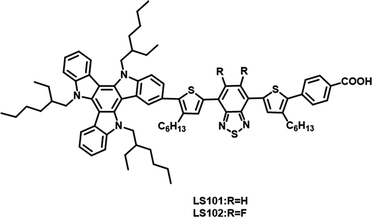
In this study, two D–π–A′–π–A photosensitizers LS101 and LS102 (Fig. 1) were synthesized with TAT as electron donor, thiophene as π-spacer, benzoic acid as anchor group, BT and DFBT as additional acceptors, respectively. DFBT was introduced to optimize the energy levels and widen the absorption spectrum response range. However, contrary to the desired result, the device containing LS102 exhibited a lower Jsc and PCE. Various tests were conducted to determine the influence of fluorine on DFBT and explain the poorer photovoltaic performance of LS102-based DSSCs. We discovered that with respect to the induction effect and conjugation effect, fluorine atoms act as electron-withdrawing and electron-donating groups, respectively. The electron-withdrawing ability of additional DFBT was impaired when the conjugation effect was dominant over the induction effect. Consequently, the band gap of LS102 was broadened and the UV-vis absorption spectrum was blue-shifted, resulting in a lower Jsc.
2. Experimental section
2.1 Synthesis
The particulars of the synthetic procedures are given in the ESI.†2.2 Solar cell fabrication
Initially, the fluorine-doped tin oxide FTO (Pilkington, 2.2 mm thick, 15 ohm square) glass plates were cleaned by sonication in soap solution, deionized water, acetone and isopropanol consecutively. Then the substrates were blown with a hair dryer and treated with UV–O3. In order to attach two dense layers to the FTO conductive glass, the substrates needed to be treated with 40 mM TiCl4 aqueous solution at 70 °C for 45 minutes, then dried by deionized water and cleaned with UV–O3. Next, the substrates were transferred to the muffle furnace and heated up to 500 °C in 3 h, then held for 1 h. After the temperature drops to 25 °C, the 4 × 4 mm2 nanocrystalline porous TiO2 transparent layer was then coated with TiO2 paste by screen printing. TPP200 was printed as a scatting layer. Then the nanoporous TiO2 electrodes were baked in the muffle furnace as before. After sintered photoanodes were cooled to 25 °C, they were immersed in dye bath (2 × 10⁻⁴ M in CH2Cl2) for 12 h. The substrates to which the dye was adsorbed served as the working electrode, Pt as the counter electrode, and the two portions were adhered by a hot-melt Surlyn film. Finally, the electrolyte is drilled into the sandwich by vacuum pump.3. Results and discussion
3.1 Optical properties and electrochemical characterization
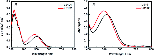
UV-vis absorption spectra of LS101 and LS102 dyes dissolved in CH2Cl2 solution (1 × 10⁻⁵ M) and adsorbed on TiO2 film are shown in Fig. 2. Table 1 shows the corresponding parameters. Compared with LS101, the maximum absorption wavelength (λmax) of LS102 was blue-shifted from 505 to 486 nm, while the molar extinction coefficient (εmax) was increased from 16![[thin space (1/6-em)]](https://www.rsc.org/images/entities/char_2009.gif) 462 to 19
462 to 19![[thin space (1/6-em)]](https://www.rsc.org/images/entities/char_2009.gif) 625 M−1 cm−1. As expected, introducing fluorine atoms increased the spectral absorption intensity, but the change in the spectral absorption range was contrary to the desired effect. When two hydrogen atoms on benzothiadiazole were substituted with highly electronegative fluorine atoms, the electron-withdrawing ability of the additional acceptor should theoretically have been enhanced. However, the results were quite different owing to the electron-donating property resulting from the conjugation effect of fluorine atoms. The effect was exemplified by the blueshift of the UV-vis absorption spectrum of LS102 in comparison to that of LS101. From Fig. 2b, when the photosensitizers were adsorbed on TiO2 film, absorption peaks of two dyes were both slightly widened and bathochromic with respect to those in CH2Cl2 solution. The extension of the absorption profile indicated that LS101 and LS102 were present on the TiO2 film in a J-aggregation state,32 which aided adequate light capture.
625 M−1 cm−1. As expected, introducing fluorine atoms increased the spectral absorption intensity, but the change in the spectral absorption range was contrary to the desired effect. When two hydrogen atoms on benzothiadiazole were substituted with highly electronegative fluorine atoms, the electron-withdrawing ability of the additional acceptor should theoretically have been enhanced. However, the results were quite different owing to the electron-donating property resulting from the conjugation effect of fluorine atoms. The effect was exemplified by the blueshift of the UV-vis absorption spectrum of LS102 in comparison to that of LS101. From Fig. 2b, when the photosensitizers were adsorbed on TiO2 film, absorption peaks of two dyes were both slightly widened and bathochromic with respect to those in CH2Cl2 solution. The extension of the absorption profile indicated that LS101 and LS102 were present on the TiO2 film in a J-aggregation state,32 which aided adequate light capture.
| Dye | λmaxa in DCM (nm) | ε (M−1 cm−1) | λmaxb on TiO2 (nm) | E0–0c (eV) | EHOMOd (V) | ELUMOe (V) | EHOMO (V) (DFT) | ELUMO (V) (DFT) |
|---|---|---|---|---|---|---|---|---|
| a Absorption maxima of dye LS101 and LS102 in CH2Cl2 solutions (1 × 10⁻⁵ M).b Absorption on TiO2 film (electrolyte: 0.1 M TFSILi and 0.85 M TBP in CH3CN).c E0–0 = 1240/λea, λea is the intersection of the tangent absorption wavelength on TiO2 film with x-axis.d EHOMO was recorded in DCM (Fc/Fc+ as an internal reference; potentials were converted to normal hydrogen electrode (NHE) by addition of 0.44 V (ref. 31)).e ELUMO = EHOMO − E0–0. | ||||||||
| LS101 | 505 | 16![[thin space (1/6-em)]](https://www.rsc.org/images/entities/char_2009.gif) 462 462 |
516 | 1.89 | 0.78 | −1.11 | 0.68 | −1.46 |
| LS102 | 486 | 19![[thin space (1/6-em)]](https://www.rsc.org/images/entities/char_2009.gif) 625 625 |
495 | 1.91 | 0.77 | −1.14 | 0.67 | −1.57 |
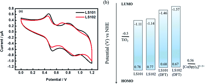
Cyclic voltammetry (CV) measurements were performed in CH2Cl2 solution (Fig. 3 and Table 1) to investigate the electrochemical properties of the two photosensitizers. For donor segments with the identical structures, the first oxidation potentials corresponding to the highest occupied molecular orbital (HOMO) energy levels of LS101 and LS102 were almost the same, at 0.78 and 0.77 V vs. NHE, respectively. These values were more positive than that of Co(bpy)32+/3+ (0.56 V vs. NHE, bpy = 2,2′-bipyridine), ensuring the driving force accessible for dye regeneration. The band gap energies (E0–0) of LS101 and LS102 were estimated as 1.89 and 1.91 eV, respectively. The LUMO energy levels were −1.11 and −1.14 V vs. NHE for LS101 and LS102. The LUMO energy levels of the two dyes were more negative than the Fermi level of TiO2 (−0.5 V vs. NHE), ensuring the sufficient driving force for the progress of electron injection. Since the electron-donating ability of the fluorine atoms in the conjugation effect exceeded the electron-withdrawing ability on the inductive effect, it dominated, making the electron-withdrawing ability of additional acceptor DFBT weakened. Therefore, the LUMO energy level of LS102 was more negative and its band gap was broader.
3.2 Theoretical calculation
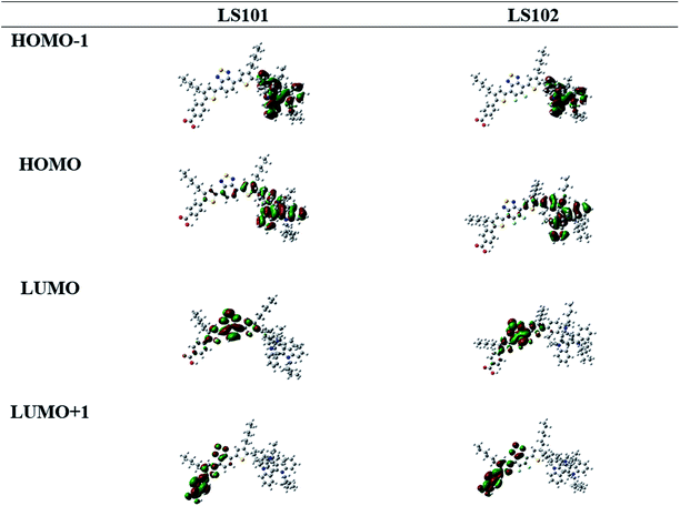
To better understand the molecular geometry and performance of LS101 and LS102 dyes, density functional theory (DFT) calculations were conducted using the Gaussian 09 program package at the B3LYP/6-311G (d, p) level. The calculated frontier molecular orbitals of dyes LS101 and LS102 are shown in Fig. 4. HOMOs of two dyes were mostly distributed on the TAT moiety and thiophene, while the HOMO−1 levels were predominantly located on the TAT donor. LUMOs were mostly delocalized on BT and DFBT, while the LUMO+1 levels were primarily located on the benzoic acid anchor group. Successful electron migration from HOMO to LUMO ensured successive charge separation and electron injection into the conduction band of TiO2.33 The HOMO, LUMO and E0–0 from DFT calculations were consistent with the values from the test (see Table 1 and Fig. 3b), with the E0–0 of LS102 found to be larger than that of LS101. This indicated that the conjugation effect of fluorine increased the LUMO level and blue-shifted its UV-vis spectrum.As we know, the conjugation effect was caused by the sp2 orbit of F atom which conjugated with overall conjugation system and donated its electron to the system. From the LUMO orbit of LS101 and LS102 (the partial enlarged orbitals were put in Fig. S1†), we can observe that the electron wave function was located on F atom in LS102, but there was no distribution of electron wave function on the corresponding H atom in LS101. The induction effect can be explained by the calculated dipole moments, LS101 and LS102 giving 7.2983 debye and 7.4563 debye respectively. With the same electron donating moiety, LS102 containing F atom on the electron withdrawing moiety gave larger dipole moment than that of LS101 containing no F atom, which meant that F atom gave electron withdrawing induction effect. The above DFT calculations successfully explained that the fluorine atom did have both the conjugation effect as the electron donor and the induction effect as electron-withdrawing group. From the UV-vis absorption spectra, the maximum absorption wavelength of LS102 was blue-shifted comparing with LS101, which illustrated the electron-withdrawing ability of DFBT was weaker than BT, so the conjugation effect was dominant.
3.3 Photovoltaic performances
To investigate the photovoltaic properties of dyes LS101 and LS102 in DSSCs, the photocurrent density–voltage (J–V) characteristics were measured (Fig. 5a) with the device parameters shown in Table 2. Under standard global AM1.5 solar irradiation (100 mW cm−2), the LS101-sensitized cell showed a higher PCE of 10.2% with a Jsc of 15.1 mA cm−2, Voc of 966 mV, and FF of 70.1%. Under the same experiment conditions, DSSCs based on LS102 exhibited a lower PCE of 8.6% (Jsc = 13.4 mA cm−2, Voc = 934 mV, FF = 69.1%). Dye loading capacity measurements were conducted to evaluate the strength of the dye–TiO2 interaction. From Table 2, LS101 showed a dye loading of 9.3 × 10⁻⁸ mol cm−2 compared with 6.5 × 10⁻⁸ mol cm−2 for LS102. Generally, a larger dye loading amount results in devices with a stronger light harvesting ability, which considerably affects the photocurrent. The dye loading measurements on TiO2 are provided in the ESI.† The devices based on LS101 showed a higher Jsc benefiting from the wide UV-vis absorption spectra (Fig. 2) and a high dye loading capacity, which compensated the disadvantageous impact of the lower molar extinction coefficient.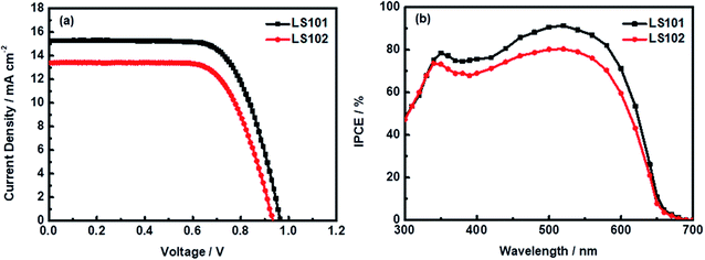 | ||
| Fig. 5 (a) Current density–voltage properties for DSSCs measured under simulated AM 1.5G illumination (b) IPCE spectra for DSSCs based on LS101 and LS102. | ||
| Dyeb | Voc (mV) | Jsc (mA cm−2) | FF (%) | PCE (%) | DLc (×10−8 mol cm−2) |
|---|---|---|---|---|---|
| a Photovoltaic performance under AM1.5 irradiation (100 mW cm−2) of the DSSCs containing LS101 and LS102 dyes. Active area of the devices is 0.16 cm−2. The cobalt-based electrolyte consists of 0.22 M [Co(bpy)3](TFSI)2, 0.05 M [Co(bpy)3](TFSI)3, 0.1 M TFSILi, and 0.85 M TBP in acetonitrile.b Dye bath: 2 × 10⁻⁴ M in CH2Cl2.c DL means the dye loading capacity on the mesoscopic TiO2 film for DSSCs. | |||||
| LS101 | 966 | 15.1 | 70.1 | 10.2 | 9.3 |
| LS102 | 934 | 13.4 | 69.1 | 8.6 | 6.5 |
To further verify the origin of the different Jsc values, the incident photon-to-current conversion efficiency (IPCE) spectrum was measured. As shown in Fig. 5b, the IPCE spectra of DSSCs based on LS101 and LS102 were both mainly observed in the wavelength range of 350–600 nm. However, the peak intensities of DSSCs containing LS101 were generally higher than those containing LS102, which contributed to the enhanced photocurrent. The maximum peak value was 91% for the device based on LS101, in contrast to that of the device based on LS102, which was only 80% at 520 nm. This trend roughly corresponded to the increase in current density.
To explore the factors affecting the differences of the Voc between devices based on LS101 and LS102, typical electrochemical impedance spectroscopy (EIS) experiments were conducted. Some relevant data are shown in Fig. 6, with specific values under −0.95 V shown in Table 3.
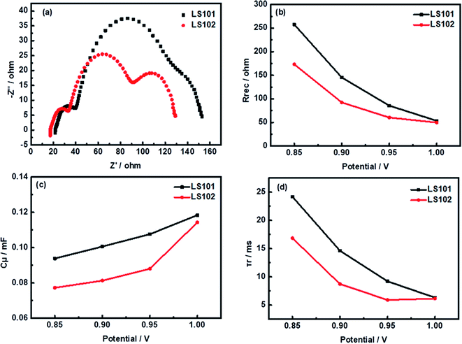 | ||
| Fig. 6 Impedance analysis: (a) Nyquist plots under forward bias of −950 mV (b) recombination resistance Rrec (c) chemical capacitance Cμ (d) calculated electron lifetime τr. | ||
| Dye | Rtr (Ω) | Rrec (Ω) | Cμ (mF) | τr (ms) | ηcc (%) |
|---|---|---|---|---|---|
| a Calculated value from EIS data measured at a forward bias of −950 mV under dark conditions. Rtr: transport resistance, Rrec: charge recombination resistance, Cμ: chemical capacitance, τr: electron lifetime, ηcc: charge-collection efficiency. | |||||
| LS101 | 18.21 | 85.58 | 0.11 | 9.21 | 82.5 |
| LS102 | 16.08 | 60.34 | 0.09 | 5.42 | 79.0 |
Using the same electrolyte, the Voc could be directly related to the position of the TiO2 conduction band (Ecb). When different dyes were adsorbed onto TiO2, its quasi-Fermi energy level will change by varying degrees. To evaluate this shift, charge transport resistance (Rtr) at Pt/electrolyte interface, electron recombination resistance (Rrec) at the TiO2/dye/electrolyte interfaces, Warburg diffusion processes (Co2+/Co3+) in the electrolyte, and chemical capacitance (Cμ) responses have been fitted with an equivalent circuit model (Fig. S3†).34–36 The resulting Nyquist plots of solar cells based on the two dyes are shown in Fig. 6a. As the same platinum electrode and electrolyte were used in the two systems, the left semicircles at high frequency corresponding to Rtr were similar. The second semicircle located in the middle-frequency region represented Rrec with the LS102 device showing a much smaller semicircle than LS101. This suggested that more serious charge recombination between injected electron and redox couple of the photoanode interface occurred in the LS102-based device under dark conditions.37 The Rrec values of LS101 and LS102 are 85.58 Ω and 60.34 Ω, respectively, at a forward bias of −950 mV (Table 3). The order of fitted Rrec values was consistent with the trend in the Voc values of LS101 and LS102. The semicircle in the low frequency region represented the impedance of the diffusion process. Since the electrolyte formulations used by the two devices based on LS101 and LS102 were exactly the same, this data had no significant difference. As shown in Fig. 6c, the Cμ responses of the DSSCs increased in the order LS101 > LS102, indicating a more negative shift in Ecb when LS101 was adsorbed on the TiO2 surface compared with LS102.38 This might account for the lower Voc of the LS102 device to a certain extent. Furthermore, Fig. 6d shows the electron lifetimes for the two dyes which were estimated using the equation (τr = Rrec × Cμ). A longer electron lifetime corresponds to a higher electron density in the TiO2 conduction band and a lower charge recombination rate, resulting in a higher Voc.39 The corresponding low Voc of LS102, which had a shorter electronic lifetime confirms this statement. The charge collection efficiency was calculated using the formula ηcc = Rrec × (Rrec + Rtr)−1. The ηcc value of LS101 was 82.5%, while that of LS102 was 79.0%, which showed that the injected electrons could be extracted more effectively in LS101, reflecting its better photovoltaic performance.40
4. Conclusion
In summary, we successfully introduced two D–π–A′–π–A organic sensitizers LS101 and LS102 with different additional acceptors BT and DFBT, respectively, for applications in DSSCs. In terms of induction effect, fluorine atoms are strong electron-withdrawing groups. However, this influence was suppressed by the electron-donating capacity of the conjugation effect from fluorine atoms, which impaired the electron-withdrawing ability of additional acceptor DFBT, resulting in LS102 having a broader band gap and narrower UV-vis absorption spectrum. Along with the weaker dye loading capacity, the devices based on LS102 had a lower Jsc (13.4 mA cm−2) than that of LS101 (15.1 mA cm−2). The LS102-based DSSCs showed a Voc of only 934 mV, compared with 966 mV for LS101, which was in agreement with the lower electron recombination resistance and chemical capacitance and shorter electron lifetime. The best PCEs achieved were 10.2% for LS101 and 8.6% for LS102. Although DFBT showed excellent photovoltaic performance in polymer solar cells and SMOSCs, this rule was not applicable to DSSCs. Improved efficiency is only possible if the properties of the molecule and the solar cell are well matched.Conflicts of interest
There are no conflicts of interest to declare.Acknowledgements
We thankfully acknowledge the financial support by the National Natural Science Foundation of China (51661135021, 21606039, U1710117).References
- M. Grätzel, J. Photochem. Photobiol., C, 2003, 4, 145–153 CrossRef.
- M. Grätzel, J. Photochem. Photobiol., A, 2004, 164, 3–14 CrossRef.
- H. Tan, C. Pan, G. Wang, Y. Wu, Y. Zhang, Y. Zou, G. Yu and M. Zhang, Org. Electron., 2013, 14, 2795–2801 CrossRef CAS.
- M. Freitag, J. Teuscher, Y. Saygili, X. Zhang, F. Giordano, P. Liska, J. Hua, S. M. Zakeeruddin, J.-E. Moser, M. Gratzel and A. Hagfeldt, Nat. Photonics, 2017, 11, 372–378 CrossRef CAS.
- Y. S. Tingare, S. V. Nguyen, H.-H. Chou, Y.-C. Liu, Y.-S. Long, T.-C. Wu, T.-C. Wei and C.-Y. Yeh, Adv. Energy Mater., 2017, 7, 11 Search PubMed.
- L. Kavan, Curr. Opin. Electrochem., 2017, 2, 88–96 CrossRef CAS.
- Y. Ren, D. Sun, Y. Cao, H. N. Tsao, Y. Yuan, S. M. Zakeeruddin, P. Wang and M. Gratzel, J. Am. Chem. Soc., 2018, 140, 2405–2408 CrossRef CAS PubMed.
- S. Soman, S. C. Pradhan, M. Yoosuf, M. V. Vinayak, S. Lingamoorthy and K. R. Gopidas, J. Phys. Chem. C, 2018, 122, 14113–14127 CrossRef CAS.
- B. O'Regan and M. Grätzel, Nature, 1991, 353, 737–740 CrossRef.
- Y. Xie, Y. Tang, W. Wu, Y. Wang, J. Liu, X. Li, H. Tian and W.-H. Zhu, J. Am. Chem. Soc., 2015, 137, 14055–14058 CrossRef CAS PubMed.
- Z. Yao, M. Zhang, H. Wu, L. Yang, R. Li and P. Wang, J. Am. Chem. Soc., 2015, 137, 3799–3802 CrossRef CAS PubMed.
- Y. K. Eom, S. H. Kang, I. T. Choi, Y. Yoo, J. Kim and H. K. Kim, J. Mater. Chem. A, 2017, 5, 2297–2308 RSC.
- W. Zhang, Y. Wu, H. W. Bahng, Y. Cao, C. Yi, Y. Saygili, J. Luo, Y. Liu, L. Kavan, J.-E. Moser, A. Hagfeldt, H. Tian, S. M. Zakeeruddin, W.-H. Zhu and M. Gratzel, Energy Environ. Sci., 2018, 11, 1779–1787 RSC.
- K. Kakiage, Y. Aoyama, T. Yano, K. Oya, J.-i. Fujisawa and M. Hanaya, Chem. Commun., 2015, 51, 15894–15897 RSC.
- S. Ahmad, E. Guillen, L. Kavan, M. Graetzel and M. K. Nazeeruddin, Energy Environ. Sci., 2013, 6, 3439–3466 RSC.
- S. Kim, J. K. Lee, S. O. Kang, J. Ko, J. H. Yum, S. Fantacci, F. De Angelis, D. Di Censo, M. K. Nazeeruddin and M. Grätzel, J. Am. Chem. Soc., 2006, 128, 16701–16707 CrossRef CAS PubMed.
- L. Zhang, X. Yang, W. Wang, G. G. Gurzadyan, J. Li, X. Li, J. An, Z. Yu, H. Wang, B. Cai, A. Hagfeldt and L. Sun, ACS Energy Lett., 2019, 4, 943–951 CrossRef CAS.
- J. Wang, S. Liu, Z. Chai, K. Chang, M. Fang, M. Han, Y. Wang, S. Li, H. Han, Q. Li and Z. Li, J. Mater. Chem. A, 2018, 6, 22256–22265 RSC.
- J.-M. Ji, S. H. Kim, H. Zhou, C. H. Kim and H. K. Kim, ACS Appl. Mater. Interfaces, 2019, 11, 24067–24077 CrossRef CAS PubMed.
- X. Gong, G. Li, Y. Wu, J. Zhang, S. Feng, Y. Liu, C. Li, W. Ma and Z. Bo, ACS Appl. Mater. Interfaces, 2017, 9, 24020–24026 CrossRef CAS PubMed.
- H. Medlej, A. Nourdine, H. Awada, M. Abbas, C. Dagron-Lartigau, G. Wantz and L. Flandin, Eur. Polym. J., 2014, 59, 25–35 CrossRef CAS.
- A. C. Stuart, J. R. Tumbleston, H. Zhou, W. Li, S. Liu, H. Ade and W. You, J. Am. Chem. Soc., 2013, 135, 1806–1815 CrossRef CAS PubMed.
- Y.-X. Xu, C.-C. Chueh, H.-L. Yip, F.-Z. Ding, Y.-X. Li, C.-Z. Li, X. Li, W.-C. Chen and A. K. Y. Jen, Adv. Mater. (Weinheim, Ger.), 2012, 24, 6356–6361 CrossRef CAS PubMed.
- Y. Zhang, S.-C. Chien, K.-S. Chen, H.-L. Yip, Y. Sun, J. A. Davies, F.-C. Chen and A. K. Y. Jen, Chem. Commun., 2011, 47, 11026–11028 RSC.
- H. Zhou, L. Yang, A. C. Stuart, S. C. Price, S. Liu and W. You, Angew. Chem., Int. Ed., 2011, 50, 2995–2998 CrossRef CAS PubMed.
- C.-Y. Chang, L. Zuo, H.-L. Yip, Y. Li, C.-Z. Li, C.-S. Hsu, Y.-J. Cheng, H. Chen and A. K. Y. Jen, Adv. Funct. Mater., 2013, 23, 5084–5090 CrossRef CAS.
- Y. Liang, Z. Xu, J. Xia, S.-T. Tsai, Y. Wu, G. Li, C. Ray and L. Yu, Adv. Mater. (Weinheim, Ger.), 2010, 22, E135–E138 CrossRef CAS PubMed.
- H. Bronstein, J. M. Frost, A. Hadipour, Y. Kim, C. B. Nielsen, R. S. Ashraf, B. P. Rand, S. Watkins and I. McCulloch, Chem. Mater., 2013, 25, 277–285 CrossRef CAS.
- S. Albrecht, S. Janietz, W. Schindler, J. Frisch, J. Kurpiers, J. Kniepert, S. Inal, P. Pingel, K. Fostiropoulos, N. Koch and D. Neher, J. Am. Chem. Soc., 2012, 134, 14932–14944 CrossRef CAS.
- N. Cho, K. Song, J. K. Lee and J. Ko, Chem. - Eur. J., 2012, 18, 11433–11439 CrossRef CAS PubMed.
- S. Li, X. Yang, D. Qu, W. Wang, Y. Wang and L. Sun, Chin. J. Chem., 2012, 30, 2315–2321 CrossRef CAS.
- X. Lu, X. Jia, Z.-S. Wang and G. Zhou, J. Mater. Chem. A, 2013, 1, 9697–9706 RSC.
- Y. Wu, W.-H. Zhu, S. M. Zakeeruddin and M. Grätzel, ACS Appl. Mater. Interfaces, 2015, 7, 9307–9318 CrossRef CAS PubMed.
- P. Brogdon, H. Cheema and J. H. Delcamp, ChemSusChem, 2017, 10, 3624–3631 CrossRef CAS PubMed.
- T. Marinado, K. Nonomura, J. Nissfolk, M. K. Karlsson, D. P. Hagberg, L. Sun, S. Mori and A. Hagfeldt, Langmuir, 2010, 26, 2592–2598 CrossRef CAS PubMed.
- J. Bisquert, Phys. Chem. Chem. Phys., 2003, 5, 5360–5364 RSC.
- K. D. Seo, B. S. You, I. T. Choi, M. J. Ju, M. You, H. S. Kang and H. K. Kim, J. Mater. Chem. A, 2013, 1, 9947–9953 RSC.
- J. N. Clifford, E. Martinez-Ferrero and E. Palomares, J. Mater. Chem., 2012, 22, 12415–12422 RSC.
- M.-L. Han, Y.-Z. Zhu, S. Liu, Q.-L. Liu, D. Ye, B. Wang and J.-Y. Zheng, J. Power Sources, 2018, 387, 117–125 CrossRef CAS.
- X. Song, X. Yang, H. Wang, J. An, Z. Yu, X. Wang, A. Hagfeldt and L. Sun, Sol. Energy, 2019, 187, 274–280 CrossRef CAS.
Footnote |
| † Electronic supplementary information (ESI) available. See DOI: 10.1039/c9ra09693k |
| This journal is © The Royal Society of Chemistry 2020 |

