 Open Access Article
In situ synthesis of CdS/CdWO4 nanorods core–shell composite via acid dissolution†
Haruki Nagakawa and
Morio Nagata
 *
*
Department of Industrial Chemistry, Graduate School of Engineering, Tokyo University of Science, 12-1 Ichigayafunagawara-cho, Shinjuku-ku, Tokyo 162-0826, Japan. E-mail: nagata@ci.tus.ac.jp
First published on 23rd December 2019
Abstract
The prevention of photocorrosion in photocatalysts allows for the use of a wide variety of visible-light-responsive photocatalysts, leading to highly efficient photocatalytic reactions. This study aimed to avoid the photocorrosion issues associated with pure CdS, a known photocorrosive photocatalyst, by forming a stable CdWO4 shell on the surface of a CdS core. The CdS/CdWO4 core–shell composite was formed using a unique method based on CdS elution under acidic conditions. An optimal CdWO4 nanorod shell was formed at a pH of 0.8, a reaction time of 30 min, and a calcination temperature of 400 °C, where the core remained intact and was sufficiently coated. The prepared CdS/CdWO4 core–shell composite was shown to be stable when exposed to light irradiation in pure water. Furthermore, it was successfully used in water splitting with an oxidation reaction side photocatalyst. This core–shell synthesis method based on core dissolution was easily and highly controlled, and is suitable for use in other similar core–shell composite applications.
Introduction
Semiconductors and metal composites offer a wide variety of properties depending on their composite morphology and the combination of materials used. Consequently, they have been broadly applied in the fields of catalysis, displays, sensors and electrochemistry.1,2 Research into composite methods has become popular in recent years. Core–shell-structured composites are a composite morphology increasingly being utilized in the field of photocatalysts. Specific functions include protection of the core material by the shell,3,4 control of the reaction by molecular permeability of the shell,5 electron confinement effect by a type I core–shell structure and carrier transfer by type II.6,7A highly efficient reaction is required to perform hydrogen production and carbon dioxide reduction using a photocatalyst.8 As the absorption of visible light is essential, photocatalysts responsive to visible light have been investigated.9 However, many of the photocatalysts with high visible light responsiveness, such as sulfide semiconductors and nitride semiconductors, have photocorrosive issues. This is an issue where hole carriers generated by photoexcitation cause the oxidative decomposition of the photocatalyst itself.10,11 To date, two approaches have been reported to suppress photocorrosion. The first is to transfer photocorrosive holes to different photocatalysts. The transfer of holes to the valence band of another photocatalyst and the consumption of holes by a Z scheme type composite have both been reported.12,13 In a previous study by the current authors, the hydrogen generation efficiency was increased by transporting the excited electrons and holes from CdS to silicon carbide. This approach successfully suppressed the photocorrosion of CdS.14,15 The second photocorrosion suppression method is to protect the photocorrosion-susceptible photocatalyst with different stable photocatalysts, thereby reducing exposure to the solution and preventing elution.16–18 The current authors reported that this method promoted the water splitting reaction in a CdS composite photocatalyst.19 However, a degree of photocorrosion occurred due to insufficient control of the morphology of the core–shell structure.
Until now, methods for synthesizing core–shell-structured materials often involved deposition of the shell onto the core by submerging the core in a solution of the shell raw material. However, conventional methods do not induce selective precipitation onto the core, and a high degree of control is required for uniform shell synthesis. The aim of this study was to establish a novel core–shell composite synthesis method. The method relied on the acid dissolution of CdS and high-level control of the CdWO4 nanorod shell morphology. This allowed for selective deposition on the CdS surface and uniform shell formation. The optimal synthesis conditions in terms of the pH, reaction time, and calcination temperature were investigated. The morphology, photocorrosion resistance, and durability of the composite in the water splitting reaction were evaluated using X-ray diffraction (XRD), diffuse reflectance spectroscopy (DRS), transmission electron microscopy (TEM), and X-ray photoelectron spectroscopy (XPS).
Experimental
Synthesis of CdS/CdWO4 core–shell composite
CdS cores were prepared based on a previously established procedure.19 20 mL of an aqueous solution containing 2.40 g of Na2S·9H2O (Wako Pure Chemical Industries Ltd., Tokyo, Japan) was added to 100 mL of an ethanol solution containing 3.08 g of Cd(NO3)2·4H2O (Kanto Chemical Co., Inc., Tokyo, Japan). The resulting precipitate was filtered and then dried at 70 °C for 24 h.The CdS/CdWO4 nanorod core–shell composite was synthesized via acid dissolution at various pH conditions. The prepared CdS powder (1.2 g) was dispersed in 100 mL of Na2WO4·2H2O (2.75 g, Kanto Chemical Co, Inc. Tokyo, Japan) solution and stirred for 24 h. Hydrochloric acid (Kanto Chemical Co., Inc. Tokyo, Japan) was added dropwise to adjust the pH values to 0.8, 1.0, or 2.0. The suspension was stirred for a short time (30 min) or long time (24 h). The mixture was centrifuged, washed with pure water, and dried at 70 °C. The powder was calcined at 200 °C or 400 °C for 2 h under Ar atmosphere. The samples calcined at 400 °C are labelled as S-08 CW (short time, pH = 0.8, CdS/CdWO4 core–shell composite), S-1 CW, S-2 CW, L-08 CW (long time, pH = 0.8, CdS/CdWO4 core–shell composite), L-1 CW, and L-2 CW.
Characterization
The synthesized composite samples were characterized by XRD (sample horizontal type multipurpose X-ray diffractometer, Ultima IV, Rigaku, Tokyo, Japan), DRS (U-3900/3900H spectrophotometer, Hitachi High-Tech Science, Tokyo, Japan), TEM (EM-002BF, JEM-2100, JEOL, Tokyo, Japan), and XPS analysis (JPS-9010MC, Mg anode, JEOL, Tokyo).Photoelectrochemical measurements
Photoelectrochemical measurements ware conducted using a three-electrode test cell equipped with a quartz window and potentiostat. To prepare the CdS/CdWO4 substrate, the prepared CdS powder, ethyl cellulose (Kanto Chemical Co., Inc., Tokyo, Japan, viscosity 45 cp), ethanol, and α-terpineol (Kanto Chemical Co., Inc., Tokyo, Japan, >96%) were homogenized to give a CdS paste. The CdS paste was coated on a freshly cleaned FTO substrate by the doctor-blade technique, and calcined at 400 °C for 30 min to form a CdS substrate. The obtained CdS substrate was immersed in a solution of 2.75 g of Na2WO4 in 100 mL of water for 24 h. Hydrochloric acid was added to adjust the pH to 0.8, following which the solution was allowed to rest for 30 min. The substrate was washed several times with water and calcined at 400 °C for 2 h to give the CdS/CdWO4 substrate. The substrate was used as the working electrode, a platinum wire was used as the counter electrode, and a silver/silver chloride (saturated KCl) electrode was used as the reference electrode. The measurements were carried out with a 300 W Xe lamp (CERMAX LX-300, ILC Technology, California, USA) and cut filter (λ > 420 nm) light source, and 0.1 M Na2S and Na2SO3 aqueous solution and 0.1 M Na2SO4 aqueous solution were used as electrolytes in the chrono amperometry and linear sweep voltammetry studies, respectively.Photo durability and photocatalytic activity test
The light durability was investigated by dispersing pure CdS and the S-08 CW core–shell composite in pure water under argon atmosphere and irradiating in visible light for 1 day. The powder was analyzed by XPS. The photocatalytic activity of the composite was evaluated using tungsten tri-oxide (WO3) as the oxidation side photocatalyst. Thus, a WO3/CdS/CdWO4 ternary composite photocatalyst was synthesized. The ternary composite was synthesized by following the procedure for sample S-08 CW (pH = 0.8; reaction time = 30 min), and 1.93 g of WO3 (Kojundo Chemical Lab. Co., Ltd., Saitama, Japan) was added during precipitation. Subsequently, 1 wt% Pt was deposited on the resulting photocatalyst using H2PtCl6·6H2O (Kanto Chemical Co., Inc., Tokyo, Japan) through photodeposition under visible light (λ > 420 nm) in a 30 vol% methanol aqueous solution. The CdS/WO3/CdWO4 (Pt 1 wt%) composite photocatalyst (0.03 g) and pure water (15 mL) were prepared in a 23 mL reaction vial. A Xe lamp with a UV cutoff filter (λ > 420 nm) was used as a visible-light source. A 0.2 mL aliquot of the evolved gas was collected using a gastight syringe, and the sampled gas was injected into the gas chromatograph (GC-8A, Shimadzu) to determine the amounts of evolved hydrogen.Results and discussion
Formation of CdWO4 nanorod shell and phase structure
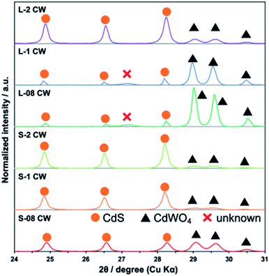
The XRD patterns of the CdS/CdWO4 core–shell composite synthesized under various conditions exhibited peaks near 24.8°, 26.5°, and 28.2° attributed to hexagonal CdS (JCPDS 65-3414) (Fig. 1). In addition, peaks near 29.0°, 29.6°, and 30.5° were attributed to CdWO4 (ICDD PDF 00-014-0676). The results confirmed that a larger proportion of CdWO4 formed under longer reaction time and lower pH conditions. Conversely, these conditions caused a decrease in the XRD peak of CdS.The XRD patterns of the CdS/CdWO4 core–shell composite synthesized under various conditions exhibited peaks near 24.8°, 26.5°, and 28.2° attributed to hexagonal CdS (JCPDS 65-3414) (Fig. 1). In addition, peaks near 29.0°, 29.6°, and 30.5° were attributed to CdWO4 (ICDD PDF 00-014-0676). The results confirmed that a larger proportion of CdWO4 formed under longer reaction time and lower pH conditions. Conversely, these conditions caused a decrease in the XRD peak of CdS.
| CdS + 2HCl → CdCl2 + H2S | (1) |
| CdCl2 + Na2WO4 → CdWO4 + 2NaCl | (2) |
 | (3) |
 | (4) |
| Ksp = [Cd2+][S2−] = 1.4 × 10⁻²⁹ | (5) |
The synthesis reaction is shown in Scheme 1. When the reaction solution was acidified by HCl, the dispersed CdS powder eluted into the solution and reacted with the WO42− ions to form the composite CdWO4 (formula (1) and (2)). Due to the solubility of CdS20 (formula (3)) and dissociation constant of H2S21 (formula (4)), the solubility of CdS increased as the pH decreased. Thus, the amount of CdWO4 generated was large under acidic conditions. When the reaction time was 24 h and the synthesis was carried out at pH = 0.8 and 1, the acid elution of CdS went too far. This resulted in CdWO4 being produced in excess and CdS being almost completely depleted. On the other hand, when the reaction time was 24 h and pH = 2, or when the reaction time was 30 min and pH = 1 and 2, the acid elution of CdS was insufficient and only a small amount of CdWO4 precipitated. The conditions of pH = 0.8 and reaction time of 30 min were found to be optimal, and CdS and CdWO4 were successfully composited.
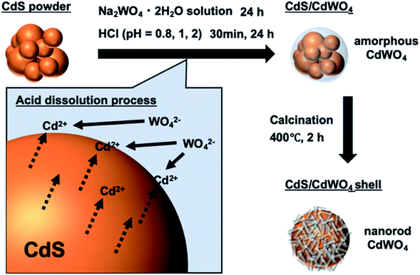 | ||
| Scheme 1 Schematic illustration of synthesis method of CdS/CdWO4 core–shell composite via acid dissolution. | ||
The XRD patterns at the two calcination temperatures of each sample are shown in Fig. S1.† From a broad peak near 26.5°, the crystal phase of CdS was determined as the cubic phase at preparation temperatures of 70 °C and 200 °C. The CdS phase was only transformed to the hexagonal phase by heating to 400 °C, and the broad peak was divided into three sharp peaks near 24.8°, 26.5°, and 28.2°. Furthermore, the peak for CdWO4 did not appear at 70 °C and 200 °C. This suggested that CdWO4 was composited to CdS in an amorphous state under low-temperature conditions.
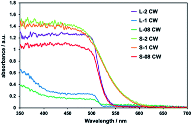
In the absorption spectra of all composites, absorption up to ca. 520 nm was observed and attributed to the presence of CdS (Fig. 2). The samples L-08 CW and L-1 CW, which had depleted CdS levels, exhibited low absorption intensities by CdS. This confirmed that as the proportion of CdS decreased, the absorption weakened. The absorption in the ultraviolet region observed in L-1 and L-08 CW was attributed to the high levels of CdWO4 due to the increased ratio of CdWO4 to CdS.
TEM was conducted to confirm the morphology of the composite. Sample S-08 CW was investigated most extensively using TEM and high-resolution TEM (HRTEM) owing to its suitable composite ratio (Fig. 3a and b). It was confirmed that the core of CdS was covered entirely by the shell of CdWO4 nanorods in S-08 CW (Fig. 3a). The interface between the CdS core and the CdWO4 shell was identified in Fig. 3b. CdWO4 covered CdS with a contact surface capable of electron transfer between CdS and CdWO4. In addition, Fig. S2† shows a TEM image of S-08 CW calcined at 200 °C. The nanoparticles covering the CdS in this sample appeared to be amorphous CdWO4, as suggested by the XRD results (Fig. S1†), and nanorod-like CdWO4 was not identified. This emphasizes the importance of increasing the temperature to 400 °C to enhance the crystallinity of CdWO4. S-2 CW was the sample in which the CdWO4 formation was lowest, and almost no CdWO4 was observed from the TEM image (Fig. 3c). Only short CdWO4 nanorods were deposited on the surface of the composite. On the other hand, the TEM image of L-08 CW, in which the proportion of CdWO4 was high, revealed only small particles of CdS, as CdS is almost completely dissolved. Large angular rod-shaped CdWO4 was observed (Fig. 3d). These results confirm that the core–shell structure of CdS/CdWO4 forms more in S-08 CW.
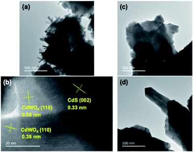 | ||
| Fig. 3 TEM and HRTEM images of the prepared CdS/CdWO4 core–shell composite photocatalysts. (a) TEM image of S-08 CW; (b) HRTEM image of S-08 CW; (c) TEM image of S-2 CW; and (d) TEM image of L-08 CW. | ||
In Fig. 4, it was observed that the intensities of the S 2p peak in the XPS profile, corresponding to the sulfur content in CdS, were the lowest for samples L-08, L-1, and S-08, among the prepared CdS/CdWO4 core–shell composite photocatalyst samples. Under the long reaction time and strong acidic conditions used to prepare these three samples, the CdS was eluted and the abundance ratio decreased. The remaining CdS was covered by the CdWO4 shell, which prevented interaction and weakened the CdS-derived peak.
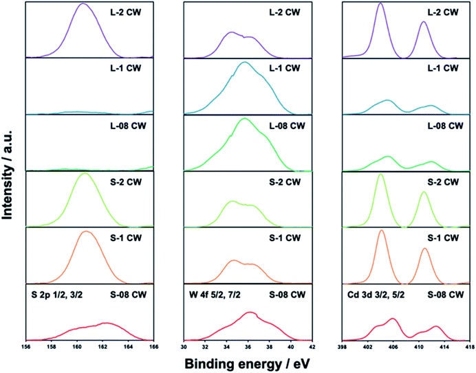 | ||
| Fig. 4 XPS profiles of the S 2p, W 4f, and Cd 3d orbitals of each prepared CdS/CdWO4 core–shell composite photocatalyst. | ||
The peak of W 4f showed the opposite tendency, with L-08, L-1, and S-08 exhibiting relatively stronger spectra than the other samples. This is due to the precipitation of a large amount of CdWO4 owing to the increased elution of Cd ions. This is inversely proportional to the decrease of the S 2p peaks. However, the W 4f peak was relatively strong in comparison with the S 2p peak. Thus, even a small amount of W composite gave rise to a strong peak. This was illustrated by the strong W 4f peaks in samples L-2, S-2, and S-1, in which it was known that only a small amount of CdWO4 was generated (Fig. 1). The difference in the ease of detection between the CdS-derived S 2p peak and the CdWO4-derived W 4f peak was attributed to CdS being confined in the core and CdWO4 being present in the shell on the surface.
The energy distribution of the S peak of S-08 CW is split into two. The higher energy peak (right) is due to elemental sulfur, attributed to the by-product of hydrogen sulfide oxidation to oxygen under acidic conditions. The peak on the high energy side was clearly observed in L-08 CW and L-1 CW where the highest amounts of CdWO4 were formed. The low energy peak (left) was derived from CdS, as CdWO4 was hardly precipitated on the surface and little hydrogen sulfide oxidation occurred. This was also prominent in samples S-1 CW, S-2 CW, and L-2 CW. As peaks reflecting both CdS and CdWO4 were observed throughout the XPS profiles of sample S-08 CW, the optimal ratio of components within the composite was further demonstrated.
Photocorrosion resistance
Light irradiation in pure water was performed on pure CdS and S-08 CW under an argon atmosphere to demonstrate the photocorrosion resistance of the prepared CdS/CdWO4 core–shell composite. As discussed earlier, a sulfur peak was identified in the XPS profiles. The change in this peak was examined after light irradiation (Fig. 5). In pure CdS, the peak on the low energy side was shifted higher (right) after light irradiation, with a maximum appearing at ca. 162 eV. This is attributed to the oxidation of the S2− state of sulfur in CdS to elemental sulfur by the holes generated during light irradiation. In the S-08 complex, no change in the spectrum was observed before and after light irradiation. Furthermore, the low energy side peak derived from CdS was retained. Thus, photocorrosion did not occur because the complexed CdWO4 prevented elution into pure water.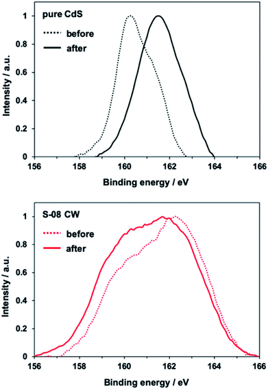 | ||
| Fig. 5 XPS S 2p profiles of pure CdS and S-08 CW before and after visible light (λ > 420 nm) irradiation for 24 h. | ||
The photocurrent was measured using CdS/CdWO4 as a working electrode to investigate the photocorrosion resistance while carrying a current (Fig. 6). The photocurrent of pure CdS decreased by 21% over 10 min due to the effects of photocorrosion (Fig. 6a). The photocurrent of CdS/CdWO4 hardly decreased when exposed to light irradiation. Furthermore, the CdS/CdWO4 composite significantly improved the photocurrent value (ca. 0.6 vs. 5 mA cm−2). There were two factors contributing to this large difference. Firstly, the prevention of rapid deterioration in the composite. CdS photocorrosion causes elemental sulfur to precipitate on the surface and even small amounts of photocatalyst decomposition can reduce the activity under light irradiation in pure water. Secondly, reverse electron transfer was suppressed. When the equilibrium potential during light irradiation was compared, the composite had a higher electromotive force (Fig. S3†). The electron carriers generated by photoexcitation were not consumed during the reduction of hydrogen ions in the electrolytic solution, thus suppressing reverse electron transfer. As a high potential brings about a strong driving force, a photocurrent resulted.
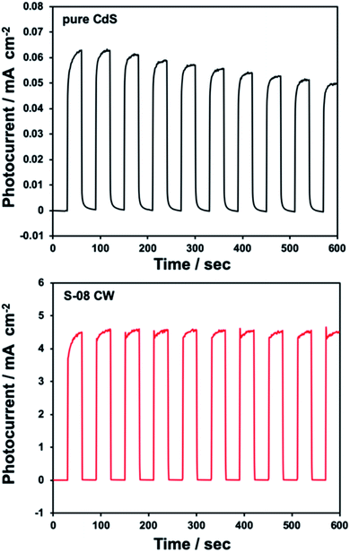 | ||
| Fig. 6 Anodic photocurrent responses under dark and illuminated conditions recorded at open circuit potential for pure CdS and S-08 CW on FTO. | ||
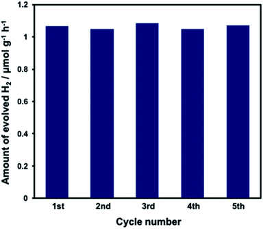
Durability in the water splitting reaction was evaluated using the WO3/CdS/CdWO4 ternary composite photocatalyst. The XRD pattern of the WO3/CdS/CdWO4 (Pt 1 wt%) composite photocatalyst is shown in Fig. S4,† and the DRS results are shown in Fig. S5.† CdWO4 was combined with WO3/CdS in a ratio similar to that of S-08 CW. Absorption in the visible light range of WO3 and CdS was observed. The addition of Pt led to additional absorption in wavebands associated with Pt. No change in the hydrogen generation activity was observed after repeated use of the composite over the course of 5 h (Fig. 7). In a previous study of the water splitting reaction using pure CdS and WO3, it was found that CdS deterioration commenced at ca. 2 h.19 In the current study, the ternary composite photocatalyst prevented the elution of CdS during light irradiation and photocorrosion was suppressed. This was attributed to the protection of CdS by the CdWO4 nanorod shell.
Conclusions
A highly controlled CdS/CdWO4 core–shell composite was synthesized by a simple method via the dissolution of CdS under acidic conditions. The eluted Cd2+ reacted with the dissolved WO42− in solution in situ, allowing selective deposition on the CdS surface for uniform shell synthesis. The synthesis conditions of pH = 0.8, reaction time = 30 min, and calcination temperature = 400 °C were found to be optimal and led to composite formation, in which the CdS core was preserved and sufficiently covered with CdWO4 nanorods. Photocorrosion by light irradiation was observed in pure CdS. However, elution of CdS to the solution was prevented in the CdS/CdWO4 core–shell composite photocatalysts, in turn, successfully preventing photocorrosion. Hydrogen production from pure water in the presence of visible light proceeded without degradation of the composite over time by using it in conjunction with the oxidation side photocatalyst. Prior to this study, most reported CdWO4 synthesis methods involved hydrothermal synthesis22–24 or solvothermal synthesis.25 These methods entailed crystal formation to obtain CdWO4 nanorods, nanofibers,22–24 and nanoparticles.25 The advantage of the method in this study is the synthesis of CdWO4 nanorods without hydrothermal synthesis or high-pressure conditions. The developed core–shell synthesis method is anticipated to be successfully applied to further advanced core–shell types due to its relative ease of use. This will be useful in the field of photocatalysis, where the use of photocorrosive photocatalysts in the water splitting reaction continues to be popular.Conflicts of interest
There are no conflicts to declare.Notes and references
- X. Lv, W. Tian, Y. Liu and Z. Y. Yuan, Mater. Chem. Front., 2019, 3, 2428–2436 RSC.
- R. G. Chaudhuri and S. Paria, Chem. Rev., 2012, 112, 2373–2433 CrossRef PubMed.
- Y. P. Xie, Z. B. Yu, G. Liu, X. L. Ma and H. M. Cheng, Energy Environ. Sci., 2014, 7, 1895–1901 RSC.
- X. Yan, Y. Liu, J. Lan, Y. Yu, J. Murowchick, X. Yang and Z. Peng, Mater. Chem. Front., 2018, 2, 96–101 RSC.
- K. Maeda, K. Teramura, D. Lu, N. Saito, Y. Inoue and K. Domen, Angew. Chem., Int. Ed., 2006, 45, 7806–7809 CrossRef CAS PubMed.
- B. O. Dabbousi, J. Rodriguez-Viejo, F. V. Mikulec, J. R. Heine, H. Mattoussi, R. K. Ober, F. Jensen and M. G. Bawendi, J. Phys. Chem. B, 1997, 101, 9463–9475 CrossRef CAS.
- S. Kim, B. Fisher, H. J. Eisler and M. Bawendi, J. Am. Chem. Soc., 2003, 125, 11466–11467 CrossRef CAS PubMed.
- K. Maeda and K. Domen, J. Phys. Chem. Lett., 2010, 1, 2655–2661 CrossRef CAS.
- A. Kudo and Y. Miseki, Chem. Soc. Rev., 2009, 38, 253–278 RSC.
- D. Meissner, C. Benndorf and R. Memming, Appl. Surf. Sci., 1987, 27, 423–436 CrossRef CAS.
- D. Meissner, R. Memming and B. Kastening, J. Phys. Chem., 1988, 92, 3476–3483 CrossRef CAS.
- Z. Wu, G. Zhao, Y. Zhang, H. Tian and D. Li, J. Phys. Chem. C, 2012, 116, 12829–12835 CrossRef CAS.
- K. Iwashina, A. Iwase, T. H. Ng, R. Amal and A. Kudo, J. Am. Chem. Soc., 2015, 137, 604–607 CrossRef CAS PubMed.
- H. Nagakawa, T. Ochiai and M. Nagata, Int. J. Hydrogen Energy, 2018, 43, 2207–2211 CrossRef CAS.
- H. Nagakawa, T. Ochiai, Y. Takekuma, S. Konuma and M. Nagata, ACS Omega, 2018, 3, 12770–12777 CrossRef CAS PubMed.
- T. Shirakawa, M. Higashi, O. Tomita and R. Abe, Sustainable Energy Fuels, 2017, 1, 1065–1073 RSC.
- A. Pareek, P. Paik and P. H. Borse, Dalton Trans., 2016, 45, 11120–11128 RSC.
- F. Jiang, Gunawan, T. Harada, Y. Kuang, T. Minegishi, K. Domen and S. Ikeda, J. Am. Chem. Soc., 2015, 137, 13691–13697 CrossRef CAS PubMed.
- H. Nagakawa, T. Ochiai, S. Konuma and M. Nagata, ACS Appl. Energy Mater., 2018, 1, 6730–6735 CrossRef CAS.
- H. C. Youn, S. Barai and J. H. Fendler, J. Phys. Chem., 1988, 92, 6320–6327 CrossRef CAS.
- M. S. Afonso and W. Stumm, Langmuir, 1992, 8, 1671–1675 CrossRef.
- H. W. Liao, Y. F. Wang, X. M. Liu, Y. D. Li and Y. T. Qian, Chem. Mater., 2000, 12, 2819–2821 CrossRef CAS.
- D. Li, X. Bai, J. Xu, X. Ma and Y. Zhu, Phys. Chem. Chem. Phys., 2014, 16, 212–218 RSC.
- I. Aslam, C. Cao, M. Tanveer, M. H. Farooq, W. S. Khan, M. Tahir, F. Idrees and S. Khalid, RSC Adv., 2015, 5, 6019–6026 RSC.
- A. J. Rondinone, M. Pawel, D. Travaglini, S. Mahurin and S. Dai, J. Colloid Interface Sci., 2007, 306, 281–284 CrossRef CAS PubMed.
Footnote |
| † Electronic supplementary information (ESI) available. See DOI: 10.1039/c9ra09858e |
| This journal is © The Royal Society of Chemistry 2020 |

