 Open Access Article
Transformation of ZIF-8 nanoparticles into 3D nitrogen-doped hierarchically porous carbon for Li–S batteries†
Guiqiang Caoa,
Da Bia,
Jingxiang Zhao b,
Jing Zhengc,
Zhikang Wanga,
Qingxue Lai*a and
Yanyu Liang
 *a
*a
aCollege of Materials Science and Technology, Nanjing University of Aeronautics and Astronautics, Nanjing 210016, P. R. China. E-mail: laiqingxue@126.com; liangyy403@126.com
bCollege of Chemistry and Chemical Engineering, Key Laboratory of Photonic and Electronic Bandgap Materials, Ministry of Education, Harbin Normal University, Harbin, 150025, China
cDepartment of Chemistry and Materials Science, College of Science, Nanjing Forestry University, Nanjing 210037, China
First published on 5th May 2020
Abstract
Li–S batteries have been attracting increasing interest owing to their remarkable advantages of low cost, high theoretical capacity and high theoretical energy density. Nevertheless, the severe “shuttle effects” of lithium polysulfides have markedly limited the performance of the cells and further hindered their commercial applications. Herein, a novel scheme combining a transformation strategy with ammonia treatment was developed to fabricate ZIF-8-derived nitrogen-doped hierarchically porous carbon (NHPC/NH3). When NHPC/NH3 was used as a host of sulfur, the obtained S@NHPC/NH3 cathode for Li–S cells presented an initial specific capacity of 1654 mA h g−1 and an outstanding cycling stability with only 0.27% attenuation per cycle from the 30th cycle to 130th cycle. Together with the theoretical calculation, it was concluded that such excellent electrochemical performances should be attributed to the suppressed “shuttle effect” via both physical and chemical adsorption of lithium polysulfides in the optimized microporous structures with effective nitrogen doping sites as well as the improved kinetics owing to the abundant meso/macroporous structures.
Introduction
With the increasing demand for energy, the exploration of high-efficiency electrochemical energy storage device is imminent.1,2 As a new energy technology, lithium-ion batteries (LIBs) have acquired enormous progress over the past 30 years.3,4 Nevertheless, their energy density reached its limit in that system.5,6 Meanwhile, Li–S batteries have been attracting attention because of their advantages including high specific capacity, high energy density, high security and environmental friendliness.7–9 Nonetheless, their application is seriously blocked by the high solubility of lithium polysulfides resulting in the irreversible loss of active materials.10,11In order to resolve the above-mentioned problem, researchers pay more attention to the cathode materials, separators, electrolytes and so on.12–15 As for the cathode materials, the typical idea is to design an electrically conductive material that can confine the active substance and relieve the movement of lithium polysulfides. Since the report of Nazar et al. on the CMK-3 conductive network,16 a variety of sulfur–carbon (C/S) composites have been employed as cathode for Li–S cells.17–19 For example, Dong et al. provided hybrid micro–mesoporous graphitic carbon spheres as sulfur containers.20 Due to their dual structure, the sulfur cathodes show superb electrochemical performance such as high specific capacity, excellent rate performance and good cycling stability. In addition, an ordered meso–microporous core–shell carbon was prepared by Huang et al., who discussed the effects of microporous and mesoporous core–shell carbon on lithium polysulfides.21 The microporous and mesoporous structure served as a barrier and an accommodation for sulfur species to improve their performance. The advantages of C/S materials as the cathode of Li–S cells are as follows: (i) the excellent electronic conductivity of carbon can ameliorate the electronic conductivity of sulfur composites; (ii) the abundant porous structure can provide a large accommodation for active materials and volume changes; (iii) the diversified structures have different functions, for example, the microporous structure exhibits a strong physical adsorption of lithium polysulfides, whereas the mesoporous and macroporous structures are conducive to the transmission of lithium ion, which results in an improved performance of the Li–S batteries.16,22–24
Recently, a great deal of studies have shown that the introduction of heteroatoms into the carbon conductive network can enhance the adsorption of lithium polysulfides on account of the nature of heteroatom doped carbons (polar) and lithium polysulfides (polar).25,26 MOFs are a kind of crystalline porous material27 and MOF (e.g., ZIF-8 and ZIF-67) derived carbon has been attracting much attention as cathode materials for Li–S batteries because of their high specific surface area, diversified structures and inner heteroatom doping.28–31 Therefore, the design of a hierarchically porous heteroatom-doped carbon such as a nitrogen doped carbon conductive network is considered as an effective strategy, which can improve the electron conductivity of the sulfur composite as well as suppress the shuttle effect of lithium polysulfides by physical confinement and chemical bonding.
Herein, ZIF-derived nitrogen-doped hierarchically porous carbon with the optimal micro/meso/macroporous structure has been fabricated as a sulfur host material by a novel transformation strategy with ammonia assisted thermal treatment. In the first step, NHPC (N represents “nitrogen-doped”, HPC represents “hierarchically porous carbon”) was synthesized through the pyrolysis of the ZIF-8/PVP composite. Subsequently, NHPC/NH3 (N represents “nitrogen-doped”, HPC represents “hierarchically porous carbon”, NH3 represents “ammonia post treatment”) was prepared by etching NHPC under an ammonia atmosphere. NHPC/NH3 has strong physical and chemical adsorption for lithium polysulfides due to their optimized micro/meso/macroporous structure and nitrogen doping. The adsorption effect on polysulfides by NHPC/NH3 was explored in a Li2S6 solution and further verified by theoretical calculation. When S@NHPC/NH3 was used as a cathode, it showed a high specific capacity of 1654 mA h g−1 and good reversibility, indicating the effectiveness of the hierarchically porous structure and nitrogen-doped carbon for the high-performance Li–S cells.
Results and discussion
The schematic of the synthesis process of NHPC and NHPC/NH3 are shown in Scheme 1. At the beginning, the ZIF-8 nanoparticles were produced through chemical bonding between zinc nitrate and 2-methylimidazole. Next, the assembly process between ZIF-8 and polyvinyl pyrrolidone (PVP) proceeded at room temperature due to the extensive electropositive zinc ions on the surface of ZIF-8 and the functional groups of PVP. With respect to the pyrolysis process, the PVP section in the intermediate of ZIF-8/PVP was already converted into an amorphous carbon network with the temperature rising to 500 °C, while the ZIF-8 nanoparticles retained its original structure. When the pyrolysis temperature increased, ZIF-8 started to decompose until 900 °C.32 Consequently, ZIF-8 nanoparticles were successfully transformed into 3D nitrogen-doped hierarchically porous carbon (NHPC) under the strong surface interaction between ZIF-8 and the PVP-derived carbon network. Eventually, NHPC/NH3 was obtained via further optimizing the micro/meso/macroporous structure of the NHPC by ammonia treatment.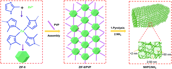 | ||
| Scheme 1 Illustration of the assembly and transformation strategy with subsequent ammonia post treatment to achieve ZIF-8-derived nitrogen-doped hierarchical carbon (NHPC/NH3). | ||
Based on the above scheme of the assembly and transformation of ZIF-8 nanoparticles into 3D nitrogen-doped hierarchically porous carbon, the physical and chemical characterizations were carried out. The X-ray diffraction (XRD) pattern and the corresponding images of ZIF-8 as shown in Fig. 1a–c, the average size of ZIF-8 nanoparticles is around 80 nm, which is well consistent with the experimental expectation. From Fig. 1a and S1a,† we found that the intensity of the diffraction peaks of ZIF-8/PVP is weakened in comparison with the counterpart of ZIF-8, which indicates that ZIF-8 was successfully crosslinked with PVP in accordance with the image of SEM (Fig. S1b†). The ratio of ZIF-8 and PVP in the intermediate was also discussed. The SEM images of NHPC with different ratios between ZIF-8 and PVP and the corresponding TEM images were shown in Fig. S2.† It is obvious that the optimum ratio is 1![[thin space (1/6-em)]](https://www.rsc.org/images/entities/char_2009.gif) :
:![[thin space (1/6-em)]](https://www.rsc.org/images/entities/char_2009.gif) 2 for the construction of ZIF-8/PVP-derived 3D well-defined porous structure. Furthermore, the diffraction peaks of the intermediate of ZIF-8/PVP disappeared in the NHPC after the pyrolysis process. To further optimize the structure of NHPC, the follow-up method of ammonia treatment was adopted. As shown in Fig. 1d–f, it is remarkable that the presence of meso/macroporous structures are observed within the NHPC/NH3 skeleton after the ammonia treatment compared to NHPC. The reason could be attributed to the replacement of carbon atoms with nitrogen in the process of NH3 treatment, thus achieving the effect of pore enlargement.33
2 for the construction of ZIF-8/PVP-derived 3D well-defined porous structure. Furthermore, the diffraction peaks of the intermediate of ZIF-8/PVP disappeared in the NHPC after the pyrolysis process. To further optimize the structure of NHPC, the follow-up method of ammonia treatment was adopted. As shown in Fig. 1d–f, it is remarkable that the presence of meso/macroporous structures are observed within the NHPC/NH3 skeleton after the ammonia treatment compared to NHPC. The reason could be attributed to the replacement of carbon atoms with nitrogen in the process of NH3 treatment, thus achieving the effect of pore enlargement.33
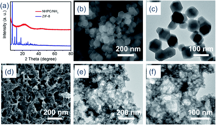 | ||
| Fig. 1 (a) XRD patterns of ZIF-8 and NHPC/NH3, (b) SEM image of ZIF-8, (c) TEM image of ZIF-8, (d) SEM image of NHPC/NH3, (e and f) TEM images of NHPC/NH3. | ||
The microscale structure of NHPC and NHPC/NH3 was characterized by nitrogen adsorption/desorption isotherm and pore size distributions, as illustrated in Fig. 2a, S3a and b.† The low-pressure adsorption curves and hysteresis loops in medium to high pressure reveal the existence of micropores and mesopores in NHPC as well as NHPC/NH3.34 NHPC/NH3 has a higher specific surface area of 1020 m2 g−1 and pore volume of 1.173 cm3 g−1 compared to that of 1013.41 m2 g−1 and 1.253 cm3 g−1 for NHPC. Meanwhile, according to Fig. 2a, we observe that the contribution of micropores to the specific surface area of NHPC/NH3 is higher than that of NHPC. Besides, the pore size distribution of NHPC/NH3 ranges from 0.6 nm to 63 nm, whereas that of NHPC ranges from 1.0 nm to 33 nm. The pore width distribution of NHPC/NH3 was shifted to the micropore direction to reveal the new microporous structures that appeared in NHPC/NH3. The result is consistent with its nitrogen adsorption/desorption isotherm. On the other hand, the presence of macropores indicates that the original pore structures were enlarged because of the etching effect of ammonia. The variety of structures is also observed in the photographs of SEM and TEM (Fig. S2† and 1d–f). The increase in the micropores can effectively alleviate the “shuttle effect” of lithium polysulfide and reduce the loss of active substances.23 Mesoporous and macroporous structures are facilely conducive to the transmission of lithium ion. In the case of NHPC/NH3, a large accommodation for the active substance is realized on account of the increment of the mesopores and macropores, accordingly, preserving the structural integrity of the cathode.35 The X-ray photoelectron spectroscopy (XPS) results of NHPC and NHPC/NH3 are illustrated in Fig. S3c,† with the content of nitrogen being 8.26 at% and 10.46 at%, respectively. The N 1s XPS patterns of NHPC and NHPC/NH3 are presented in Fig. 2b and c, which reveal the presence of five different types of nitrogen, namely pyridinic N, pyrrolic N, graphitic N, quaternary N and –NO2 with binding energies at 398.53 eV, 399.65 eV, 400.8 eV, 402.4 eV and 404.80 eV, respectively. Fig. 2d illustrates the N 1s XPS patterns of the difference between NHPC/NH3 and NHPC, which indicates the type of increased nitrogen including pyridinic N, pyrrolic N, graphitic N. Consequently, the higher content of nitrogen and the optimized micro/meso/macroporous structure will endow NHPC/NH3 with strong lithium polysulfide adsorption ability.25,26
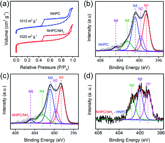 | ||
| Fig. 2 (a) Nitrogen adsorption/desorption isotherm, (b and c) N 1s XPS patterns of NHPC and NHPC/NH3, (d) N 1s XPS patterns of the difference between NHPC/NH3 and NHPC. | ||
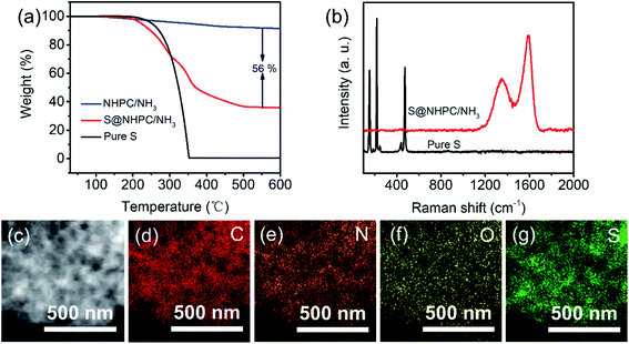
S@NHPC/NH3 as the cathode for Li–S batteries was prepared by a conventional melt-diffusion process36 at 155 °C. The TG curve of S@NHPC/NH3 is shown in Fig. 3a, and the calculated content of sulfur in S@NHPC/NH3 is 56 wt%. Raman spectra of Pure S and S@NHPC/NH3 are shown in Fig. 3b. S@NHPC/NH3 provided the typical characteristic D band at 1356 cm−1 and G band at 1590 cm−1 of carbon. It should be noted that the Raman spectrum of Pure S disappeared in S@NHPC/NH3, which means that there is a uniform distribution of most of the sulfur in S@NHPC/NH3. In addition, there is no obvious sulfur found in the SEM image of S@NHPC/NH3 (Fig. S4†). The STEM image of S@NHPC/NH3 and the elemental mapping results of carbon, nitrogen, oxygen and sulfur are shown in Fig. 3c–g. The results are in good agreement with the Raman spectrum and the SEM image of S@NHPC/NH3. The specific surface area of S@NHPC/NH3 was decreased to 196.76 m2 g−1 and the pore size distribution was about 3 nm (Fig. S5†), showing that the pores within NHPC/NH3 are occupied by sulfur.
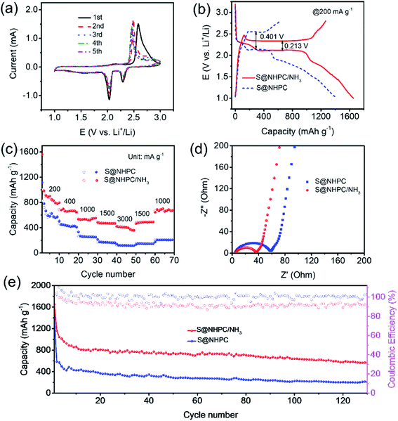
The electrochemical performance of NHPC/NH3 as a sulfur host in Li–S batteries was assessed in the form of coin cells with a S@NHPC/NH3 cathode, a lithium metal anode and a polypropylene separator. In addition, coin cells using the S@NHPC cathode were also assembled under the same condition for comparison. The cyclic voltammetry (CV) curve of the S@NHPC/NH3 cathode is shown in Fig. 4a. The cathodic peak of 2.3 V is reasonably assigned to the reduction of sulfur into long-chain lithium polysulfides (Li2Sn, 4 ≤ n ≤ 8), while the cathodic peak at about 2.0 V should be attributed to long-chain lithium polysulfides that are transformed into short-chain lithium polysulfides (Li2Sn, 2 ≤ n < 4). The anodic peak at 2.5 V is ascribed to the conversion of short-chain lithium polysulfides to sulfur. Notably, the anodic peak that migrates to the negative direction after the first cycle is attributed to the unstable system in the beginning. In comparison, with the CV curve of the S@NHPC cathode (Fig. S6a†), it is clear that the cathodic peaks are shifted to the positive direction whereas the anodic peaks are shifted to the negative direction in the case of the S@NHPC/NH3 cathode. As shown in Fig. 4b, the three discharge potential plateaus (at ∼2.3 V, ∼2.1 V and ∼1.7 V) represent the conversion of S8 to Li2Sn (4 ≤ n ≤ 8), Li2Sn (4 ≤ n ≤ 8) transforming to Li2Sn (2 ≤ n ≤ 3) and the formation of Li2S2/Li2S. The charge potential plateaus (at ∼2.3 V) represent the conversion of Li2S2/Li2S to sulfur. Meanwhile, the overpotential of the S@NHPC/NH3 cathode is 0.213 V while it is 0.401 V for the S@NHPC cathode, suggesting the improvement of redox kinetics after the ammonia assisted treatment, which is attributed to the presence of the macroporous structure. The specific capacities of the S@NHPC/NH3 cathode (Fig. 4b and S6b†) is 1654 and 1340 mA h g−1 at the current density of 200 mA g−1 and 400 mA g−1 in the first cycle process, respectively. In contrast, the S@NHPC cathode delivers 1417 mA h g−1 and 1206 mA h g−1 under the same condition. The initial discharge capacities of S@NHPC/NH3 and S@NHPC are higher than their charge capacities owing to the presence of by-products in the first discharge process. Besides, a large amount of sulfur appeared on the surface of NHPC (Fig. S7†), which reduced the utilization of active substance. The rate performance of S@NHPC/NH3 and S@NHPC cathodes at different current densities are shown in Fig. 4c. With the increase in the current density from 200 to 3000 mA g−1, the specific capacities in the first discharge cycle of the S@NHPC/NH3 cathode is 1563, 684, 537, 485, and 422 mA h g−1. However, the S@NHPC cathode exhibits an awful rate performance; it only delivers 1115, 454, 332, 213, and 140 mA h g−1 at the rate of 200, 400, 1000, 2000 and 3000 mA g−1, respectively. These results indicate that the meso/macroporous structure of the NHPC/NH3 material promotes charge transport and the microporous structure restrains the shuttle effect of lithium polysulfides by NH3 etching. The electrochemical impedance spectra of the S@NHPC and S@NHPC/NH3 cathodes (before cycle) are shown in Fig. 4d. The charge transfer resistance of the S@NHPC/NH3 cathode is lower than that of the S@NHPC cathode, indicating the with rapid electron and Li-ion transport of the S@NHPC/NH3 cathode in the redox process. The cycling performance of the S@NHPC/NH3 and S@NHPC cathodes is further investigated, as demonstrated in Fig. 4e. The former delivers a specific capacity of 568 mA h g−1 after 130 cycles, while the latter obtains a specific capacity of 327 mA h g−1 after 30 cycles. These enhanced electrochemical performances are rationally attributed to the fact that the hierarchical structure not only possesses a strong adsorption capacity to inhibit the migration of lithium polysulfides due to the abundant microporous structure, but also improves the Li-ion diffusion rate through the meso/microporous framework.37,38 Owing to the existence of a large number of microporous structures in materials, the voltage range of the electrochemical test was set to 1–3 V to release the full capacities, and the coulombic efficiency was lower than that of the S@NHPC cathode.39 Further, the electrochemical impedance spectra of the S@NHPC/NH3 cathode (after cycle) is shown in Fig. S8,† indicating that NHPC/NH3 has good stability. NHPC/NH3 as a host for Li–S batteries delivers an outstanding capacity along with stable cycle performance. This can be rationally attributed to the optimized micro/meso/macroporous structure and high nitrogen content of the NHPC/NH3 material. (i) The homogeneously distributed hierarchical porosity within the NHPC/NH3 skeleton can promote ion transport. (ii) The combination of the elevated proportion of micropore with high nitrogen doping can effectively suppress the “shuttle effect” via both physical confinement and chemical adsorption of lithium polysulfides during the continuous charge–discharge process.
To gain better insight into the adsorption effects of the N-doped carbon, on the one hand, we conducted the adsorption test of NHPC and NHPC/NH3 for lithium polysulfides. Fig. S9† shows the image of a Li2S6 solution (0) and that with the addition of NHPC (1) and NHPC/NH3 (2) for 3 h. It can be seen that the solution containing NHPC/NH3 is colorless while the solution of NHPC retains the pristine color. On the other hand, we carried out density functional theory (DFT) calculation to simulate the binding of polysulfides on these substrates where the Li2S6 species was chosen as a representative since it is a common intermediate in Li–S batteries. The optimized geometrical structures of Li2S6 species on NHPC/NH3 and the corresponding binding energies are presented in Fig. 5. According to the summaries of recent theoretical studies, the optimal binding energy of soluble polysulfides on the anchoring material are in the range from 0.80 to 2.00 eV.40–42 Our simulations revealed that the binding energy of the Li2S6 species on the graphitic N-dopant (one carbon atom is substituted by one N atom) is only 0.51 eV, suggesting a considerably weak adsorption. Thus, Li2S6 species is very likely to diffuse away from the cathode to the organic solvent, leading to the obvious shuttling effects. On the contrary, the doping of pyridinic- or pyrrolic-N leads to a much stronger binding strength with Li2S6 species, and the binding energies are 1.45 and 1.33 eV, respectively. These computational results have demonstrated our experimental observations about the distinct anchoring capabilities of pyridinic N or pyrrolic N for Li–S batteries.
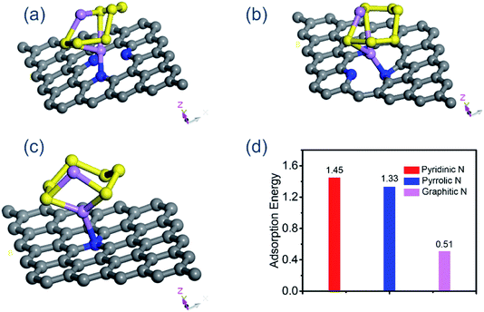 | ||
| Fig. 5 (a) The view of a Li2S6 molecule on the pyridinic N, (b) pyrrolic N, (c) graphitic N, (d) the corresponding binding energy. | ||
Conclusions
In summary, a novel transformation strategy assisted with ammonia treatment was successfully developed to fabricate ZIF-8-derived nitrogen-doped hierarchically porous carbon (NHPC/NH3). As a sulfur host for Li–S batteries, on the one hand, the meso/macroporous structure leads to the fast reaction kinetics. On the other hand, the microporous structure and strong anchoring capabilities of pyridinic N or pyrrolic N effectively alleviate the “shuttle effect”. Consequently, it presented a higher specific capacity of 1654 mA h g−1 and satisfactory cycle sturdiness. The proposed scheme provides a way for the modification of novel carbon materials for energy storage.Experimental
Assembly of the ZIF-8 nanoparticle
At the beginning, 6.0 g Zn(NO3)2·6H2O and 13.2 g 2-mIm were dissolved in 280 mL methanol. Next, the above two solutions were mixed together and stirred for 24 h at 20 °C, followed by centrifugation and washing with methanol for three times and vacuum drying at 60 °C to obtain the ZIF-8 nanoparticles.Preparation of NHPC and NHPC/NH3
As for ZIF-8/PVP, 200 mg ZIF-8 and 400 mg PVP were dissolved in 10 mL and 15 mL methanol after which the two solutions were mixed together and stirred until the solvent evaporated completely. Then, ZIF-8/PVP was carbonized at 900 °C under N2 atmosphere and kept for 2 h. Subsequently, the products were poured into 0.5 M H2SO4 for 12 h and washed with distilled water to neutrality. NHPC was obtained after vacuum drying at 60 °C for 24 h. NHPC/NH3 was prepared by etching NHPC under NH3 atmosphere. Typically, NHPC was treated at 900 °C under N2 atmosphere, followed by treatment under NH3 for a few minutes. Finally, NHPC/NH3 was obtained after cooling to room temperature.Preparation of the sulfur cathodes
In general, NHPC/NH3 and sulfur powder were mixed through grinding for 30 min. Then, the mixture was added to a sealed vacuum vessel and heated for 12 h at 155 °C to obtain S@NHPC/NH3. The cathode electrodes are composed of 70 wt% active material S@NHPC/NH3, 20 wt% Super P and 10 wt% binder (poly(vinylidene fluoride)), which were coated on an Al foil and dried under vacuum at 60 °C for 12 h. Finally, the electrode was cut into a coin-shape with a diameter of 12 mm and dried at 60 °C for 2 h.Materials characterization
The morphology of the samples was investigated by SEM and TEM. XRD patterns were analyzed by BRUKER D8, Cu Kα. Nitrogen adsorption/desorption isotherm were recorded with a Micromeritics ASAP 2020 instrument at 77 K. XPS was tested by Kratos AXIS Ultra spectrometer with a source gun of Al Kα and spot size of 400 μm. Raman spectra were recorded on a Lab-RAM HR800 (Horiba Jobin Yvon).Electrochemical measurement
CR2016-type coin cells were assembled in an Ar-filled glovebox. Lithium metal foil was used as the anode, aluminum metal foil was used as the current collector and Celgard 2400 was used as the separator. The galvanostatic charge–discharge equipment was used to carry out electrochemical measurement. Cyclic voltammetry (CV) was performed with 0.1 mV s−1 scan rate and electrochemical impedance spectroscopy (EIS) was performed with an amplitude of 5 mV from 10−2 to 105 Hz.Conflicts of interest
There are no conflicts to declare.Acknowledgements
The authors thank the support from the National Natural Science Foundation of China (Grant No. 21771107 and No. 21902077), the Natural Science Foundation of Jiangsu Province (Grant No. BK20190381).References
- P. Yang and J. M. Tarascon, Nat. Mater., 2012, 11, 560 CrossRef CAS PubMed.
- J. B. Goodenough, Acc. Chem. Res., 2012, 46, 1053–1061 CrossRef PubMed.
- J. Tarascon and M. Armand, Nature, 2001, 414, 359–367 CrossRef CAS PubMed.
- B. L. Ellis, K. T. Lee and L. F. Nazar, Chem. Mater., 2010, 22, 691–714 CrossRef CAS.
- V. Etacheri, R. Marom, R. Elazari, G. Salitra and D. Aurbach, Energy Environ. Sci., 2011, 4, 3243–3262 RSC.
- P. G. Bruce, S. A. Freunberger, L. J. Hardwick and J.-M. Tarascon, Nat. Mater., 2012, 11, 19 CrossRef CAS PubMed.
- A. Manthiram, S. H. Chung and C. Zu, Adv. Mater., 2015, 27, 1980–2006 CrossRef CAS PubMed.
- L. Borchardt, M. Oschatz and S. Kaskel, Chem.–Eur. J., 2016, 22, 7324–7351 CrossRef CAS PubMed.
- Y. Song, S. Zhao, Y. Chen, J. Cai, J. Li, Q.-H. Yang, J. Sun and Z. Liu, ACS Appl. Mater. Interfaces, 2019, 11, 5687–5694 CrossRef CAS PubMed.
- M.-K. Song, E. J. Cairns and Y. Zhang, Nanoscale, 2013, 5, 2186–2204 RSC.
- Y. Pang, Y. Xu, Y. Li, F. Xu, L. Sun, J. Yang, H.-W. Li and S. Zheng, ACS Appl. Energy Mater., 2019, 2, 1537–1543 CrossRef CAS.
- G. Li, J. Sun, W. Hou, S. Jiang, Y. Huang and J. Geng, Nat. Commun., 2016, 7, 10601 CrossRef CAS PubMed.
- F. Pei, L. Lin, A. Fu, S. Mo, D. Ou, X. Fang and N. Zheng, Joule, 2018, 2, 323–336 CrossRef CAS.
- H. Du, S. Li, H. Qu, B. Lu, X. Wang, J. Chai, H. Zhang, J. Ma, Z. Zhang and G. Cui, J. Membr. Sci., 2018, 550, 399–406 CrossRef CAS.
- E. Cha, M. D. Patel, J. Park, J. Hwang, V. Prasad, K. Cho and W. Choi, Nat. Nanotechnol., 2018, 13, 337 CrossRef CAS PubMed.
- X. L. Ji, K. T. Lee and L. F. Nazar, Nat. Mater., 2009, 8, 500–506 CrossRef CAS PubMed.
- W. Kang, L. Fan, N. Deng, H. Zhao, Q. Li, M. Naebe, J. Yan and B. Cheng, Chem. Eng. J., 2018, 333, 185–190 CrossRef CAS.
- C. Hernández-Rentero, R. Córdoba, N. Moreno, A. Caballero, J. Morales, M. Olivares-Marín and V. Gómez-Serrano, Nano Res., 2018, 11, 89–100 CrossRef.
- S. Huang, L. Zhang, J. Wang, J. Zhu and P. K. Shen, Nano Res., 2018, 11, 1731–1743 CrossRef CAS.
- J. Zheng, G. Guo, H. Li, L. Wang, B. Wang, H. Yu, Y. Yan, D. Yang and A. Dong, ACS Energy Lett., 2017, 2, 1105–1114 CrossRef CAS.
- Z. Li, Y. Jiang, L. Yuan, Z. Yi, C. Wu, Y. Liu, P. Strasser and Y. Huang, ACS Nano, 2014, 8, 9295–9303 CrossRef CAS PubMed.
- C. Tang, Q. Zhang, M. Q. Zhao, J. Q. Huang, X. B. Cheng, G. L. Tian, H. J. Peng and F. Wei, Adv. Mater., 2014, 26, 6100–6105 CrossRef CAS PubMed.
- S.-H. Yeon, K.-N. Jung, S. Yoon, K.-H. Shin, C.-S. Jin and Y. Kim, J. Appl. Electrochem., 2013, 43, 245–252 CrossRef CAS.
- P. Strubel, S. Thieme, T. Biemelt, A. Helmer, M. Oschatz, J. Brückner, H. Althues and S. Kaskel, Adv. Funct. Mater., 2015, 25, 287–297 CrossRef CAS.
- W. Ai, W. Zhou, Z. Du, Y. Chen, Z. Sun, C. Wu, C. Zou, C. Li, W. Huang and T. Yu, Energy Storage Materials, 2017, 6, 112–118 CrossRef.
- J. Cai, C. Wu, Y. Zhu, K. Zhang and P. K. Shen, J. Power Sources, 2017, 341, 165–174 CrossRef CAS.
- Y. Peng, Y. Li, Y. Ban and W. Yang, Angew. Chem., Int. Ed., 2017, 56, 9757–9761 CrossRef CAS PubMed.
- J. He, Y. Chen and A. Manthiram, iScience, 2018, 4, 36 CrossRef CAS PubMed.
- Y.-Q. Lu, Y.-J. Wu, T. Sheng, X.-X. Peng, Z.-G. Gao, S.-J. Zhang, L. Deng, R. Nie, J. Światowska and J.-T. Li, ACS Appl. Mater. Interfaces, 2018, 10, 13499–13508 CrossRef CAS PubMed.
- X.-J. Hong, T.-X. Tan, Y.-K. Guo, X.-Y. Tang, J.-Y. Wang, W. Qin and Y.-P. Cai, Nanoscale, 2018, 10, 2774–2780 RSC.
- F. Yu, H. Zhou and Q. Shen, J. Alloys Compd., 2019, 772, 843–851 CrossRef CAS.
- Q. Lai, Y. Zhao, Y. Liang, J. He and J. Chen, Adv. Funct. Mater., 2016, 26, 8334–8344 CrossRef CAS.
- Q. Liang, Z. Li, Z. H. Huang, F. Kang and Q. H. Yang, Adv. Funct. Mater., 2015, 25, 6885–6892 CrossRef CAS.
- K. S. Sing, D. H. Everett, R. Haul, L. Moscou, R. A. Pierotti, J. Rouquerol and T. Siemieniewska, Pure Appl. Chem., 1985, 57, 603–619 CAS.
- R. Fang, S. Zhao, Z. Sun, D. W. Wang, H. M. Cheng and F. Li, Adv. Mater., 2017, 29, 1606823 CrossRef PubMed.
- X. Ji, S. Evers, R. Black and L. F. Nazar, Nat. Commun., 2011, 2, 325 CrossRef PubMed.
- X. Yang, Y. Li, P. Zhang, L. Sun, X. Ren and H. Mi, Carbon, 2020, 157, 70–79 CrossRef CAS.
- X. Yang, Z. Ran, F. Luo, Y. Li, P. Zhang and H. Mi, Appl. Surf. Sci., 2020, 509, 145270 CrossRef CAS.
- Z. Chang, B. Ding, H. Dou, J. Wang, G. Xu and X. Zhang, Chem.–Eur. J., 2018, 24, 3768–3775 CrossRef CAS PubMed.
- Q. Zhang, Y. Wang, Z. W. Seh, Z. Fu, R. Zhang and Y. Cui, Nano Lett., 2015, 15, 3780–3786 CrossRef CAS PubMed.
- J. Zhao, Y. Yang, R. S. Katiyar and Z. Chen, J. Mater. Chem. A, 2016, 4, 6124–6130 RSC.
- Y. Zhao and J. Zhao, Appl. Surf. Sci., 2017, 412, 591–598 CrossRef CAS.
Footnote |
† Electronic supplementary information (ESI) available: XRD pattern of ZIF-8/PVP; SEM images of ZIF-8/PVP and NHPC with a ZIF-8/PVP ratio of 1![[thin space (1/6-em)]](https://www.rsc.org/images/entities/char_2009.gif) : :![[thin space (1/6-em)]](https://www.rsc.org/images/entities/char_2009.gif) 1, 1 1, 1![[thin space (1/6-em)]](https://www.rsc.org/images/entities/char_2009.gif) : :![[thin space (1/6-em)]](https://www.rsc.org/images/entities/char_2009.gif) 2, 1 2, 1![[thin space (1/6-em)]](https://www.rsc.org/images/entities/char_2009.gif) : :![[thin space (1/6-em)]](https://www.rsc.org/images/entities/char_2009.gif) 3 and S@NHPC and S@NHPC/NH3 with a ZIF-8/PVP ratio of 1 3 and S@NHPC and S@NHPC/NH3 with a ZIF-8/PVP ratio of 1![[thin space (1/6-em)]](https://www.rsc.org/images/entities/char_2009.gif) : :![[thin space (1/6-em)]](https://www.rsc.org/images/entities/char_2009.gif) 2; TEM images at different ratios; XPS survey of NHPC and NHPC/NH3 and NHPC/NH3–NHPC; TG curves of S@NHPC, NHPC and Pure S; nitrogen adsorption/desorption isotherm and pore size distributions of S@NHPC/NH3. Cyclic voltammetry of the S@NHPC cathode; charge/discharge profiles of the S@NHPC and the S@NHPC/NH3 cathodes at 400 mA g−1, EIS of S@NHPC/NH3 cathodes before cycle and after cycle at 200 mA g−1; the pore size distributions of NHPC and NHPC/NH3. See DOI: 10.1039/c9ra10063f 2; TEM images at different ratios; XPS survey of NHPC and NHPC/NH3 and NHPC/NH3–NHPC; TG curves of S@NHPC, NHPC and Pure S; nitrogen adsorption/desorption isotherm and pore size distributions of S@NHPC/NH3. Cyclic voltammetry of the S@NHPC cathode; charge/discharge profiles of the S@NHPC and the S@NHPC/NH3 cathodes at 400 mA g−1, EIS of S@NHPC/NH3 cathodes before cycle and after cycle at 200 mA g−1; the pore size distributions of NHPC and NHPC/NH3. See DOI: 10.1039/c9ra10063f |
| This journal is © The Royal Society of Chemistry 2020 |

