 Open Access Article
Redox-active glyme–Li tetrahalogenoferrate(III) solvate ionic liquids for semi-liquid lithium secondary batteries†
Yuta Kemmizakia,
Yu Katayama *a,
Hiromori Tsutsumia and
Kazuhide Ueno
 *b
*b
aDepartment of Applied Chemistry, Graduate School of Sciences and Technology for Innovation, Yamaguchi University, Tokiwadai, Ube 755-8611, Japan. E-mail: yuktym@yamaguchi-u.ac.jp; Fax: +81-836-85-9285; Tel: +81-836-85-9285
bDepartment of Chemistry and Biotechnology, Yokohama National University, 79-5 Tokiwadai, Hodogaya-ku, Yokohama 240-8501, Japan. E-mail: ueno-kazuhide-rc@ynu.ac.jp; Fax: +81-45-339-3951; Tel: +81-45-339-3951
First published on 24th January 2020
Abstract
Solvate ionic liquids (SILs), comprising long-lived, Li solvate cations and counter anions, serve as highly Li-ion-conductive and non-flammable electrolytes for use in lithium secondary batteries. In this work, we synthesized a series of novel redox-active glyme(oligoether)–Li salt-based SILs, consisting of a symmetric ([Li(G3)]+) or asymmetric ([Li(G3Bu)]+) triglyme–Li salt complex and redox-active tetrahalogenoferrate ([FeX]− (X = Br4, Cl3Br, Cl4)), for use as the catholyte in semi-liquid lithium secondary batteries. The successful formation of stable molten complexes of [Li(G3/G3Bu)][FeX] was confirmed by Raman spectroscopy and thermogravimetry. The melting point (Tm) depended on both the molecular weights of the complex anions and the structures of the complex cations. [Li(G3)][FeCl4] comprised complex cations with a symmetric structure, and the smallest complex anions showed the lowest Tm of 28.2 °C. The redox properties of the [FeX]−/[FeX]2− couple strongly suggested the suitability of [Li(G3/G3Bu)][FeX] as a catholyte. The discharge capacities of semi-liquid lithium secondary batteries utilizing the [Li(G3/G3Bu)][FeX] catholyte depended on the structure of the SILs, and the cell with [Li(G3)][FeCl4] showed the highest capacity with relatively good capacity retention. This study confirmed the feasibility of the glyme-based redox-active SILs as catholytes for scalable redox-flow type batteries.
1. Introduction
There is a social demand for sustainable energy alternatives, including renewable energy sources and sustainable energy storage systems, to satisfy environmental criteria. Some renewable energy sources, such as wind and solar power, contribute some electrical energy, but this is inherently intermittent and dispersed.1 To fully utilize renewable energy sources, it is essential to develop highly efficient energy storage systems.2 In this context, lithium secondary batteries with high energy densities have attracted attention,3,4 and significant effort has been devoted to improving their performance.5,6Organic solvent-based electrolytes have been used in lithium secondary batteries due to their high ionic conductivity and wide electrochemical windows, which are both necessary to achieve better battery performances.7 Although organic electrolytes have transport and electrochemical properties ideal for high energy density batteries, their high volatility and flammability pose serious safety concerns.8–11 Ionic liquids (ILs) composed entirely of salt are inherently minimally volatile and non-flammable,12,13 and therefore IL-based electrolytes have been considered promising candidates for a next-generation electrolyte for safe secondary batteries14–20 and non-aqueous flow-type batteries,21–26 in an effort to address the issues associated with organic electrolytes.
Nonetheless, the overall battery performance is sometimes limited by the poor Li+ ion transport properties of typical IL-based electrolytes doped with Li salt resulting from factors such as high viscosity, low ionic conductivity, and low Li+ ion carrier density. Solvate ionic liquids (SILs), in which the cations and/or anions of the salts are strongly coordinated with ligand molecules in discrete complex ions, are a new subset of ILs with the potential to solve these problems.24 Compared to typical IL-based battery electrolytes, SILs with high concentrations of Li+ ions were found to provide better Li+ ion transport properties27 as well as comparable electrochemical potential windows (>4 V) due to strong binding between the ligand and metal cations.28–31 Typical SILs, such as [Li(G3)][TFSA], an equimolar mixture of triethylene glycol dimethyl ether (G3) and lithium bis(trifluoromethanesulfonyl) amide (LiTFSA), have been revealed as efficient electrolytes for lithium–sulfur batteries, in terms of their high coulombic efficiency, high capacity, and long cycle life.32 Meanwhile, the glyme-based SILs were found to show an extremely low lithium transference number of 0.026 under anion blocking conditions, which is a similar situation to realistic battery systems.33,34 This may negatively affect the battery performance, especially for rate capability. In the SIL-based electrolyte, the complex cation ([Li(G3)]+) serves as a Li+ ion carrier, whereas the TFSA anion merely maintains its electrical neutrality.
The glyme-based SILs also find applications in organic and material chemistry,35–37 and there has also been studies of the solid–liquid interface38–40 and solvent polarities.41–43 Our group has extended the SIL concept further and was recently successful in developing a redox-active SIL, [Li(G3)][FeBr4], comprised solely of complex ions, that could serve as a “two-in-one” functional catholyte for semi-liquid lithium secondary batteries; the [Li(G3)]+ complex cation serves as a Li+ ion carrier, while the [FeBr4]− complex anion undergoes a redox reaction as the catholyte.44 Here, the weakly coordinating properties of the [FeBr4]− complex anion ensures strong ligand–Li+ ion interactions and a high degree of dissociation, as well as a relatively low melting point (Tm), all of which have been reported as critical in yielding SILs.45 However, the redox-active SIL with [FeBr4]− has a Tm of 80 °C (solid at room temperature) and has been mixed with other redox-inactive SILs to achieve ambient-temperature operation of semi-liquid lithium batteries at the expense of energy density (i.e., catholyte concentration).44 Therefore, it is crucial to reduce the melting point of redox-active SILs to expand the operating temperature range and increase the energy density of semi-liquid lithium batteries. Understanding the molecular interactions within the SILs is also important in obtaining redox-active SILs with further improved thermal, transport, and electrochemical properties.
Ions with asymmetric structures or distorted shapes have been considered effective in lowering the Tm of organic salts.46,47 In this work, we synthesized a series of redox-active SILs consisting of a symmetric ([Li(G3)]+) or asymmetric ([Li(G3Bu)]+) triglyme–Li complex with redox-active tetrahalogenoferrate ([FeX]− (X = Br4, Cl3Br, Cl4)) to study the effect of molecular structure on their Tm and transport properties. The thermal and physicochemical properties and coordination structure of [Li(G3/G3Bu)][FeX] were investigated using differential scanning calorimetry (DSC), thermogravimetry (TG), Raman spectroscopy, and electrochemical measurements. Semi-liquid lithium batteries utilizing [Li(G3/G3Bu)][FeX] as a component of their catholyte were further studied.
2. Experimental
2.1. Materials
Purified G3 (Nippon Nyukazai), triethylene glycol butyl methyl ether (G3Bu, Wako), LiTFSA (battery-grade, Solvay Chemicals), lithium bromide (>99.0%, Tokyo Chemical Industry), lithium chloride (Ishizu Seiyaku), iron(III) bromide (99%, Wako), and iron(III) chloride (99%, Kojundo Chemical Laboratory) were used as received. All SILs were prepared in an Ar-filled glove box ([H2O] < 3.5 ppm). LiBr and G3 were mixed at a 1![[thin space (1/6-em)]](https://www.rsc.org/images/entities/char_2009.gif) :
:![[thin space (1/6-em)]](https://www.rsc.org/images/entities/char_2009.gif) 1 molar ratio and heated at 120 °C for at least 12 h to obtain [Li(G3)]Br. [Li(G3Bu)]Br was prepared by mixing LiBr and G3Bu at a 1
1 molar ratio and heated at 120 °C for at least 12 h to obtain [Li(G3)]Br. [Li(G3Bu)]Br was prepared by mixing LiBr and G3Bu at a 1![[thin space (1/6-em)]](https://www.rsc.org/images/entities/char_2009.gif) :
:![[thin space (1/6-em)]](https://www.rsc.org/images/entities/char_2009.gif) 1 molar ratio and heating at 100 °C for at least 12 h. [Li(G3)][FeBr4] and [Li(G3)][FeCl3Br] were prepared by mixing [Li(G3)]Br and FeBr3 or FeCl3, respectively, at a 1
1 molar ratio and heating at 100 °C for at least 12 h. [Li(G3)][FeBr4] and [Li(G3)][FeCl3Br] were prepared by mixing [Li(G3)]Br and FeBr3 or FeCl3, respectively, at a 1![[thin space (1/6-em)]](https://www.rsc.org/images/entities/char_2009.gif) :
:![[thin space (1/6-em)]](https://www.rsc.org/images/entities/char_2009.gif) 1 molar ratio, and heating at 100 °C for at least 12 h. [Li(G3Bu)][FeBr4] and [Li(G3Bu)][FeCl3Br] were prepared in the same way, using [Li(G3Bu)]Br rather than [Li(G3)]Br. [Li(G3)][FeCl4] and [Li(G3Bu)][FeCl4] were prepared by mixing LiFeCl4 and G3 or G3Bu, at 100 °C or room temperature, respectively, for at least 12 h. The LiFeCl4 used here was obtained by grinding LiCl and FeCl3 powders in a mortar at a 1
1 molar ratio, and heating at 100 °C for at least 12 h. [Li(G3Bu)][FeBr4] and [Li(G3Bu)][FeCl3Br] were prepared in the same way, using [Li(G3Bu)]Br rather than [Li(G3)]Br. [Li(G3)][FeCl4] and [Li(G3Bu)][FeCl4] were prepared by mixing LiFeCl4 and G3 or G3Bu, at 100 °C or room temperature, respectively, for at least 12 h. The LiFeCl4 used here was obtained by grinding LiCl and FeCl3 powders in a mortar at a 1![[thin space (1/6-em)]](https://www.rsc.org/images/entities/char_2009.gif) :
:![[thin space (1/6-em)]](https://www.rsc.org/images/entities/char_2009.gif) 1 molar ratio. [Li(G3)][TFSA] and [Li(G3Bu)][TFSA] were prepared according to a procedure described elsewhere.28
1 molar ratio. [Li(G3)][TFSA] and [Li(G3Bu)][TFSA] were prepared according to a procedure described elsewhere.28
2.2. Measurements
TG analysis (TGA) was performed with a Thermo plus EVO II instrument (Rigaku), from room temperature to 800 °C, at a heating rate of 20 °C min−1 under a helium atmosphere. The thermal decomposition temperature (Td) was defined as the temperature at which 5% weight loss occurred in the TGA curves. The Tm of each SIL was determined by DSC (DSC7020, Hitachi High-Tech Science). The samples were hermetically sealed in aluminum (alodined) pans in a glove box. The samples were heated to 100 °C, cooled to −100 °C, and then reheated from −100 °C to 100 °C, at a sweep rate of 10 °C min−1. Each Tm was determined from the peak temperature of the endothermic melting peaks in the heating thermograms.Raman spectroscopy was performed using an NRS-3100 Raman spectrometer with 785.23 nm excitation (JASCO Inc.). All the spectra shown in this work were calibrated using a silicon standard.
Cyclic voltammetry (CV) was performed using an SP-150 potentiostat (Bio Logic), with a three-electrode cell, in the glove box. Glassy carbon (GC) and platinum plate were used as the working electrode and counter electrode, respectively. The Li metal electrode (Honjo Metal) was soaked in 1 M LiTFSA, in G3 (see the ESI, Fig. S1†), and used as a Li/Li+ reference electrode. Note that the Li/Li+ reference electrode was separated from the sample solutions with Vycor glass. The potentials shown in this study were converted to a Li/Li+ scale (VLi), unless otherwise noted.
The galvanostatic charge–discharge measurements were performed with an automatic charge–discharge instrument (HJ1001SM8A, Hokuto Denko) at 30 °C. Carbon paper (200 μm thick, Chemix) and a lithium metal electrode were used as the current collector and anode, respectively. A lithium-ion-conducting glass–ceramic (OHARA, LICGC) was used to prevent redox shuttle of the redox-active anions between the electrodes. The catholyte ([Li(G3/G3Bu)][FeX]![[thin space (1/6-em)]](https://www.rsc.org/images/entities/char_2009.gif) :
:![[thin space (1/6-em)]](https://www.rsc.org/images/entities/char_2009.gif) [Li(G3/G3Bu)][TFSA] = x
[Li(G3/G3Bu)][TFSA] = x![[thin space (1/6-em)]](https://www.rsc.org/images/entities/char_2009.gif) :
:![[thin space (1/6-em)]](https://www.rsc.org/images/entities/char_2009.gif) y (molar ratio)) and the anolyte ([Li(G3/G3Bu)][TFSA]) (40 μL each) were infiltrated into a porous glass filter paper. The cell was assembled in the glove box. The cut-off potentials were set to 2.5 V and 3.3 V for the discharge and charge steps, respectively. The cell was initially in the fully charged state, and thus the charge–discharge cycle was defined as follows: 1st discharge → 2nd charge → 2nd discharge → 3rd charge. The coulombic efficiency was defined as: Nth discharge capacity/Nth charge capacity. The specific capacity was calculated based on the mass of the redox-active SIL in the catholytes. The charge–discharge current density (C-rate) was calculated based on the theoretical capacity of the redox-active SILs [Li(G3/G3Bu)][FeX].
y (molar ratio)) and the anolyte ([Li(G3/G3Bu)][TFSA]) (40 μL each) were infiltrated into a porous glass filter paper. The cell was assembled in the glove box. The cut-off potentials were set to 2.5 V and 3.3 V for the discharge and charge steps, respectively. The cell was initially in the fully charged state, and thus the charge–discharge cycle was defined as follows: 1st discharge → 2nd charge → 2nd discharge → 3rd charge. The coulombic efficiency was defined as: Nth discharge capacity/Nth charge capacity. The specific capacity was calculated based on the mass of the redox-active SIL in the catholytes. The charge–discharge current density (C-rate) was calculated based on the theoretical capacity of the redox-active SILs [Li(G3/G3Bu)][FeX].
3. Results and discussion
3.1. Coordination structure of SILs
The formation of the highly stable complex cations and anions, [Li(G3/G3Bu)]+ and [FeX]− (X = Br4, Cl3Br, Cl4), was confirmed by Raman spectroscopy and TGA (Fig. 1, 2, S2, and S3†).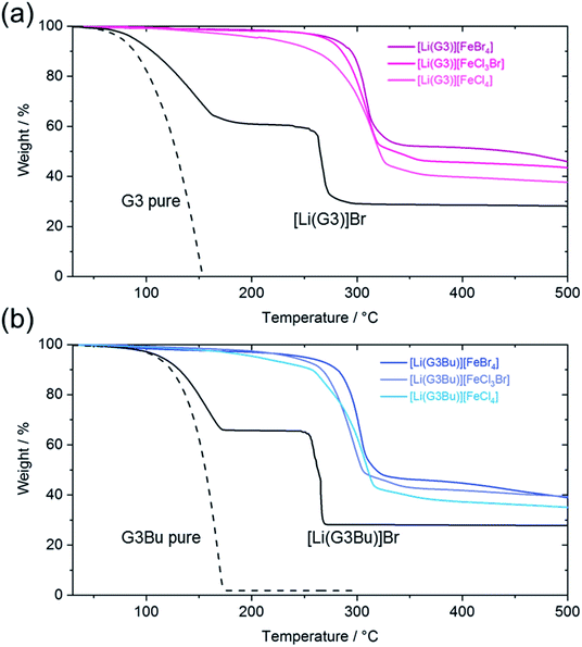 | ||
| Fig. 2 Thermogravimetric curves for: (a) [Li(G3)][FeX] (X = Br4, Cl3Br, Cl4), [Li(G3)]Br, and pure G3; and (b) [Li(G3Bu)][FeX] (X = Br4, Cl3Br, Cl4), [Li(G3Bu)]Br, and pure G3Bu. | ||
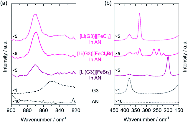
Fig. 1a shows Raman spectra for the C–O stretching and CH2 rocking regions, which are commonly used to study the coordination structures of glyme–Li+ complex cations.48 A broad peak at ∼850 cm−1, observed for G3, corresponds to the disordered conformation of the chain structure of the glyme.49 To study the coordination structure of [Li(G3)][FeX] (X = Br4, Cl3Br, Cl4), the corresponding SILs were diluted with acetonitrile (AN) to minimize the effect of the parasitic fluorescence. For [Li(G3)][FeX] (X = Br4, Cl3Br, Cl4), the band at 850 cm−1 completely disappeared, and a unique peak appeared at ∼870 cm−1, which was attributed to [Li(G3)]+ complex cations having a crown-ether like (12-crown-4) conformation in the AN solutions (breathing mode).49 From these results, the existence of stable [Li(G3)]+ complex cations with the crown-ether-like conformation were confirmed for the Li(G3) systems. Unfortunately, the breathing mode of complex cations with asymmetric glyme (G3Bu) was not readily discernible because of the strong fluorescence, even in AN solutions (Fig. S2a†).
The formation of [FeX]− (X = Br4, Cl3Br, Cl4) complex anions was also investigated by Raman spectroscopy. Raman spectra of [Li(G3)][FeBr4] and [Li(G3)][FeCl4] showed sharp peaks at ∼200 and 330 cm−1, which were assigned to the symmetric Fe–Br and Fe–Cl stretching modes of [FeBr4]− and [FeCl4]−, respectively (Fig. 1b).50–53 [Li(G3)][FeCl3Br] showed peaks at 223, 245, 265, 330, and 350 cm−1, which could be attributed to asymmetric [FeCl3Br]− according to the literature.50,54 Since there were no visible bands corresponding to the precursors (FeBr3, FeCl3, and AN),52 [FeX]− (X = Br4, Cl3Br, Cl4) complex anions were evidently formed for all SILs (for the Li(G3Bu) system, please see Fig. S2b†). The formation of stable complex cations and anions of [Li(G3)][FeX] (X = Br4, Cl3Br, Cl4) in the AN solution was thus confirmed.
TG measurement was performed to study the thermal stability of the prepared SILs. The TG curve for pure G3 indicated the evaporation of G3 at ∼100 °C, which was consistent with the literature value.24 The equimolar addition of LiBr to G3 significantly affected the thermogravimetric curves, where two weight loss steps were observed at ∼150 °C and ∼250 °C. The first weight loss was attributable to the evaporation of the uncoordinated G3, while the latter could be attributed to the evaporation of coordinated G3 in [Li(G3)]+ complex cations, as supported by the following arguments. Firstly, the thermal stability of G3 was improved by formation of the [Li(G3)]+ complex, due to the interaction between the Li+ ions and G3 ligands. Secondly, the amount of weight loss depended on the LiBr![[thin space (1/6-em)]](https://www.rsc.org/images/entities/char_2009.gif) :
:![[thin space (1/6-em)]](https://www.rsc.org/images/entities/char_2009.gif) G3 molar ratio, which is, adding more LiBr (more [Li(G3)]+ in the system) could lead to reduced weight loss at ∼200 °C (see Fig. S3†). In our previous study, a significant number of glyme molecules remained uncoordinated in equimolar molten complexes of G3 and Li salts with highly basic anions due to a chemical equilibrium between the reactant (lithium salt with free solvent) and product (complex cation with counter-anion).48 Therefore, the above scenario is feasible for the two-step weight loss of [Li(G3)]Br. [Li(G3)][FeX] (X = Br4, Cl3Br, Cl4) showed only one step of weight loss at ∼300 °C (Fig. 2a). The remarkable increase in the thermal decomposition temperature of [Li(G3)][FeX] systems can be explained by the enhanced interaction between the Li+ and G3 ligands within the [Li(G3)]+ complexes, caused by reduction of the cation (Li+) to anion ([FeX]−) interaction, due to the charge-delocalization within [FeX]− complex anions.44 The absence of weight loss at ∼200 °C suggested that uncoordinated G3 was almost absent, and stable [Li(G3)]+ complexes were present in most [Li(G3)][FeX] systems, which was consistent with the Raman spectra obtained for [Li(G3)][FeX] in AN solutions (Fig. 1). As shown in Fig. 2b, the TG curves for [Li(G3Bu)][FeX] (X = Br4, Cl3Br, Cl4) also showed one step of weight loss at ∼300 °C, indicating the formation of stable [Li(G3Bu)]+ complexes and a scarcity of uncoordinated glymes for all [Li(G3Br)][FeX] systems in the molten state.
G3 molar ratio, which is, adding more LiBr (more [Li(G3)]+ in the system) could lead to reduced weight loss at ∼200 °C (see Fig. S3†). In our previous study, a significant number of glyme molecules remained uncoordinated in equimolar molten complexes of G3 and Li salts with highly basic anions due to a chemical equilibrium between the reactant (lithium salt with free solvent) and product (complex cation with counter-anion).48 Therefore, the above scenario is feasible for the two-step weight loss of [Li(G3)]Br. [Li(G3)][FeX] (X = Br4, Cl3Br, Cl4) showed only one step of weight loss at ∼300 °C (Fig. 2a). The remarkable increase in the thermal decomposition temperature of [Li(G3)][FeX] systems can be explained by the enhanced interaction between the Li+ and G3 ligands within the [Li(G3)]+ complexes, caused by reduction of the cation (Li+) to anion ([FeX]−) interaction, due to the charge-delocalization within [FeX]− complex anions.44 The absence of weight loss at ∼200 °C suggested that uncoordinated G3 was almost absent, and stable [Li(G3)]+ complexes were present in most [Li(G3)][FeX] systems, which was consistent with the Raman spectra obtained for [Li(G3)][FeX] in AN solutions (Fig. 1). As shown in Fig. 2b, the TG curves for [Li(G3Bu)][FeX] (X = Br4, Cl3Br, Cl4) also showed one step of weight loss at ∼300 °C, indicating the formation of stable [Li(G3Bu)]+ complexes and a scarcity of uncoordinated glymes for all [Li(G3Br)][FeX] systems in the molten state.
Both [Li(G3/G3Bu)]+ and [FeX]− (X = Br4, Cl3Br, Cl4) complex ions were thus successfully formed and were stable in both the molten state and in the AN solutions. The above results supported the argument that [Li(G3)][FeX] comprised the stable complex ions, [Li(G3)]+ and [FeX]−.
3.2. Effect of molecular structure on melting point
The Tm of [Li(G3/G3Bu)][FeX] (X = Br4, Cl3Br, Cl4) was determined by DSC (Fig. 3). As noted previously, the Tm of [Li(G3)][FeBr4] was ∼80 °C,44 which met the traditionally accepted definition of ILs, that is, salts that melt below 100 °C.12 Although [Li(G3)][FeBr4] had weak interionic interactions, due to the charge-delocalization of [FeBr4]−, the Tm observed was relatively high, probably due to the symmetric tetrahedral structure of [FeBr4]−, as with [Li(G3)]BF4 (Tm = 90 °C) and [Li(G3)]ClO4 (Tm = 103 °C).44,55 The melting points of [Li(G3)][FeCl3Br]− and [Li(G3)][FeCl4]− were 45.3 °C and 28.2 °C, respectively, and the Tm clearly decreased when Br in the complex anions was replaced by Cl. A similar lowering of Tm on replacing Br with Cl was also reported for tetrabutylammonium tetrahalogenoferrate salts.56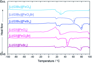 | ||
| Fig. 3 DSC curves for the SILs [LiG3/G3Br][FeX] (X = Br4, Cl3Br, Cl4) at 10 °C min−1. The melting point was determined by the endothermic peak position (as indicated by down arrows). | ||
It appears that the Tm depends on the molecular weight of the complex anions rather than the asymmetric structure of the constituent ions, which was considered to lower the Tm of typical ILs. A possible factor determining Tm is the strength of the dispersion forces within the complexes, which depends mainly on the sum of molecular polarizability of the complex cation and complex anion. Lower polarizability of [FeCl4]− than [FeBr4]− (i.e., lower polarizability of Cl than Br) would result in weaker dispersion forces within complexes, leading to melting point depression. The DSC curves for [Li(G3Bu)][FeX] (X = Br4, Cl3Br, Cl4) further supported this theory; [Li(G3Bu)][FeBr4] showed the highest Tm (Tm = 79.7 °C), followed by [Li(G3Bu)][FeCl3Br] (Tm = 61.4 °C) and [Li(G3Bu)][FeCl4] (Tm = 29.4 °C). [Li(G3Bu)][FeCl3Br] showed higher Tm value than did [Li(G3)][FeCl3Br]. However, Tm values of the [Li(G3)] and [Li(G3Bu)] systems were nearly identical if the complex anions are [FeCl4]− or [FeBr4]−. Therefore, we conclude that Tm depends presumably on the molecular polarizability of the complex anions, and [Li(G3)][FeCl4] showed the lowest Tm.
3.3. Electrochemical properties
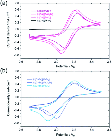
The redox properties of a [Li(G3/G3Bu)][FeX] (X = Br4, Cl3Br, Cl4)–[Li(G3/G3Bu)][TFSA] mixture (5/95) were studied using CV, to clarify the suitability of [Li(G3/G3Br)][FeX] (X = Br4, Cl3Br, Cl4) as a catholyte for semi-liquid lithium batteries (Fig. 4).Cyclic voltammograms for the [Li(G3)] systems showed clear redox peaks around 3.1 VLi, which were assigned to the reaction of the Fe(II)/Fe(III) redox couple in the complex anion, i.e., [FeX]− + e− ⇄ [FeX]2− (X = Br4, Cl3Br, Cl4) (Fig. 4a). The redox potentials of [Li(G3)][FeCl3Br] (∼3.05 VLi) and [Li(G3)][FeCl4] (∼3.05 VLi) were slightly lower than that of [Li(G3)][FeBr4] (∼3.1 VLi), suggesting the effect of either ligand or solvent donor properties in the SILs. The redox potential of Fe(II)/Fe(III) has been known to become more negative under more Lewis basic conditions;57 thus, the observations suggest that smaller [FeCl3Br]− and [FeCl4]− provided a more Lewis basic environment. A similar trend was observed for the [Li(G3Bu)] systems, which showed both a redox peak at 3.0 VLi and a negative shift in the redox potential for [FeCl3Br]− and [FeCl4]− anions (Fig. 4b). The differences between the anodic and cathodic peak potentials, ΔEp, were 140–180 and 180–300 mV for the [Li(G3)] and [Li(G3Bu)] systems, respectively. The theoretical value for a reversible, one-electron charge transfer reaction, such as [FeBr4]−/[FeBr4]2−, is 60 mV, which suggests that the redox reactions of Fe(II)/Fe(III) were closer to those of the reversible system for the [Li(G3)] systems, and quasi-reversible for the [Li(G3Bu)] systems. The larger ΔEp observed for the [Li(G3Bu)] systems implied that the longer terminated alkyl chain of the complex cations was responsible for the sluggish charge transfer kinetics of the redox-active anions at the interface. Nevertheless, the cyclic voltammograms indicated the potential application of [Li(G3/G3Bu)][FeX] (X = Br4, Cl3Br, Cl4) as a catholyte.
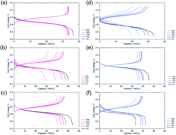
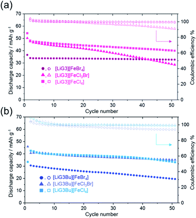
To demonstrate the suitability of the [Li(G3/G3Bu)][FeX] (X = Br4, Cl3Br, Cl4) catholyte for semi-liquid lithium batteries, charge–discharge tests were performed using Li|[Li(G3/G3Bu)][TFSA]|LICGC|[Li(G3/G3Bu)][FeX4] (X = Br4, Cl3Br, Cl4)–[Li(G3/G3Bu)][TFSA] mixed cells (Fig. 5). Here LICGC was placed between the catholyte and the Li metal anode to prevent shuttling of the [Fe(III)X]−/[Fe(II)X]2− redox couple, which was fatal to battery operation. Fig. 5a–f show charge and discharge curves from the 1st cycle to the 50th cycle, at 0.2 °C and 30 °C. Fig. 5a and d show charge and discharge curves for the catholyte, with [Li(G3)][FeBr4] and [Li(G3Bu)][FeBr4], respectively. The cycle dependences of the discharge capacities and coulombic efficiencies of each cell are shown in Fig. 6.
As shown in Fig. 5, the initial discharge capacity was higher than those at the other cycles (except for the cell with [Li(G3Bu)][FeCl4] shown in Fig. 5f), and the coulombic efficiency of the 2nd cycle slightly exceeded 100%. These results imply side reactions, possibly due to impurities in the cells, during discharge during the initial stage of the charge–discharge tests. However, all the cells showed reversible charge–discharge behavior after a few cycles as evident from the ∼100% efficiency (Fig. 6). The average cell voltage hardly differed among the cells and was in the range 2.85–2.95 V, corresponding to the observed redox potential range of 3.0–3.1 VLi shown in Fig. 4. The lower cell voltage compared to the redox potential of the catholytes is attributable to the positive Nernst potential shift of the Li anode with a higher Li salt concentration: highly concentrated [Li(G3/G3Bu)][TFSA] (3.1 M for G3 and 2.6 M for G3Bu) was used as the anolyte in the cells, whereas CV was performed using a Li/Li+ reference electrode soaked in 1 M LiTFSA/G3.48
The discharge capacity of each cell depended on the theoretical capacity, which was based on the mass of [Li(G3/G3Br)][FeX] (X = Br4, Cl3Br, Cl4) (see Table 1); the SIL-based catholyte with smaller complex ions delivered a higher capacity. However, the capacity of all the cells decreased to 60%–70% of the theoretical capacity at the 5th discharge cycle (see Fig. S4†). The low utilization of the catholytes was probably due to the suboptimal cell conditions, such as the low surface area of the CP current collector. The cell with [Li(G3)][FeBr4] showed stable charge–discharge cycles as demonstrated by the capacity retention of >90% and the coulombic efficiency of >99.5% after 50 cycles (Fig. 6); however, its capacity was the lowest. The capacity of the other cells gradually decreased with cycling, suggesting decreased stability of the catholytes during repeated charge and discharge. The reduced form of the redox-active SILs, which is a dianion complex, may become less soluble with smaller complex anions containing Cl and precipitate in the catholyte, leading to capacity decay.23 For the [Li(G3Bu)] systems, less reversible redox properties observed by CV may also have influenced the capacity degradation. Further investigation is necessary to clarify the detailed reasons. Among those tested, the cell with [Li(G3)][FeCl4] achieved the highest capacity of ∼40 mA h g−1, a relatively high capacity retention of 74%, and a coulombic efficiency of 99.3% after 50 cycles.
| SILs | Molecular weight/g mol−1 | Theoretical capacity/mA h g−1 |
|---|---|---|
| [Li(G3)][FeBr4] | 560.64 | 47.8 |
| [Li(G3)][FeCl3Br] | 427.28 | 62.7 |
| [Li(G3)][FeCl4] | 382.82 | 70.0 |
| [Li(G3Bu)][FeBr4] | 602.72 | 44.5 |
| [Li(G3Bu)][FeCl3Br] | 469.36 | 57.1 |
| [Li(G3Bu)][FeCl4] | 424.9 | 63.1 |
4. Conclusions
SILs consisting of both symmetric and asymmetric glyme–Li complex cations and tetrahalogenoferrate(III) complex anions were prepared to study the effect of molecular structure on the thermal and electrochemical properties. By combining Raman spectroscopy and TG, the coordination structures of the SILs were shown to be the expected crown-ether like complex cations and tetrahedral [FeX] complex anions. DSC revealed that Tm decreased with the molecular weight in the anion complexes, with [Li(G3)][FeCl4] and [Li(G3Bu)][FeCl4] showing the lowest Tm in this study (≈30 °C). A [Li(G3/G3Bu)][FeX]–[Li(G3/G3Bu)][TFSA] mixed electrolyte showed a well-defined Fe(II)/Fe(III) redox reaction of the complex anions, which confirmed its suitability as a catholyte for semi-liquid lithium batteries. Although all the cells exhibited reversible charge–discharge cycles, the cell with [Li(G3)][FeCl4] showed the highest capacity among the SILs tested after 50 cycles.To increase the energy density of semi-liquid lithium secondary batteries, it is crucial to increase the concentration of active species in the catholytes while maintaining the liquid state. A [Li(G3)][FeCl4] catholyte, with the lowest Tm and the highest capacity, can potentially improve the energy density, although the capacity degradation needs to be further addressed. However, the [Li(G3Bu)] systems did not improve the Tm or the battery performance. The results presented here provide an insight into the molecular design of IL-based catholytes to improve the performance, including efficiency, energy density, and cycle life, of IL-based semi-liquid lithium batteries with flow-battery-like scalability.
Author contributions
The manuscript was written through contributions of all authors. All authors have given approval to the final version of the manuscript.Conflicts of interest
There are no conflicts to declare.Acknowledgements
This study was supported in part by the JSPS KAKENHI (Grant No. 19K15360 to Y. K., 16H04647 to H. T., and 16H06053 to K. U.) from the Japan Society for the Promotion of Science (JSPS).References
- P. Alotto, M. Guarnieri and F. Moro, Renewable Sustainable Energy Rev., 2014, 29, 325–335 CrossRef CAS.
- B. Dunn, H. Kamath and J.-M. Tarascon, Science, 2011, 334, 928–935 CrossRef CAS.
- X.-B. Cheng, R. Zhang, C.-Z. Zhao and Q. Zhang, Chem. Rev., 2017, 117, 10403–10473 CrossRef CAS PubMed.
- Y. Nishi, J. Power Sources, 2001, 100, 101–106 CrossRef CAS.
- B. Scrosati, J. Hassoun and Y.-K. Sun, Energy Environ. Sci., 2011, 4, 3287–3295 RSC.
- L. Xia, L. Yu, D. Hu and G. Z. Chen, Mater. Chem. Front., 2017, 1, 584–618 RSC.
- M. Galiński, A. Lewandowski and I. Stępniak, Electrochim. Acta, 2006, 51, 5567–5580 CrossRef.
- F. Cheng, J. Liang, Z. Tao and J. Chen, Adv. Mater., 2011, 23, 1695–1715 CrossRef CAS PubMed.
- K. Xu, Chem. Rev., 2004, 104, 4303–4418 CrossRef CAS PubMed.
- K. Xu, Chem. Rev., 2014, 114, 11503–11618 CrossRef CAS PubMed.
- Y. Sasaki, Electrochemistry, 2008, 76, 2–15 CrossRef CAS.
- R. D. Rogers and K. R. Seddon, Science, 2003, 302, 792–793 CrossRef PubMed.
- M. Watanabe, M. L. Thomas, S. Zhang, K. Ueno, T. Yasuda and K. Dokko, Chem. Rev., 2017, 117, 7190–7239 CrossRef CAS PubMed.
- M. Forsyth, H. Yoon, F. F. Chen, H. J. Zhu, D. R. MacFarlane, M. Armand and P. C. Howlett, J. Phys. Chem. C, 2016, 120, 4276–4286 CrossRef CAS.
- Q. W. Yang, Z. Q. Zhang, X. G. Sun, Y. S. Hu, H. B. Xing and S. Dai, Chem. Soc. Rev., 2018, 47, 2020–2064 RSC.
- A. Lewandowski and A. Świderska-Mocek, J. Power Sources, 2009, 194, 601–609 CrossRef CAS.
- G. A. Giffin, A. Moretti, S. Jeong and S. Passerini, J. Phys. Chem. C, 2014, 118, 9966–9973 CrossRef CAS.
- M. Balaish, A. Kraytsberg and Y. Ein-Eli, Phys. Chem. Chem. Phys., 2014, 16, 2801–2822 RSC.
- M.-C. Lin, M. Gong, B. Lu, Y. Wu, D.-Y. Wang, M. Guan, M. Angell, C. Chen, J. Yang, B.-J. Hwang and H. Dai, Nature, 2015, 520, 324 CrossRef CAS PubMed.
- J. Scheers, S. Fantini and P. Johansson, J. Power Sources, 2014, 255, 204–218 CrossRef CAS.
- K. Takechi, Y. Kato and Y. Hase, Adv. Mater., 2015, 27, 2501–2506 CrossRef CAS PubMed.
- Y. Li, J. Sniekers, J. Malaquias, X. Li, S. Schaltin, L. Stappers, K. Binnemans, J. Fransaer and I. F. J. Vankelecom, Electrochim. Acta, 2017, 236, 116–121 CrossRef CAS.
- L. Xue, T. G. Tucker and C. A. Angell, Adv. Energy Mater., 2015, 5, 1500271 CrossRef.
- M. Watanabe, K. Dokko, K. Ueno and M. L. Thomas, Bull. Chem. Soc. Jpn., 2018, 91, 1660–1682 CrossRef CAS.
- D. Lloyd, T. Vainikka, M. Ronkainen and K. Kontturi, Electrochim. Acta, 2013, 109, 843–851 CrossRef CAS.
- A. Ejigu, P. A. Greatorex-Davies and D. A. Walsh, Electrochem. Commun., 2015, 54, 55–59 CrossRef CAS.
- K. Yoshida, M. Tsuchiya, N. Tachikawa, K. Dokko and M. Watanabe, J. Electrochem. Soc., 2012, 159, A1005–A1012 CrossRef CAS.
- K. Yoshida, M. Nakamura, Y. Kazue, N. Tachikawa, S. Tsuzuki, S. Seki, K. Dokko and M. Watanabe, J. Am. Chem. Soc., 2011, 133, 13121–13129 CrossRef CAS PubMed.
- H. Moon, R. Tatara, T. Mandai, K. Ueno, K. Yoshida, N. Tachikawa, T. Yasuda, K. Dokko and M. Watanabe, J. Phys. Chem. C, 2014, 118, 20246–20256 CrossRef CAS.
- T. M. Pappenfus, W. A. Henderson, B. B. Owens, K. R. Mann and W. H. Smyrl, J. Electrochem. Soc., 2004, 151, A209–A215 CrossRef CAS.
- S. Seki, N. Serizawa, K. Takei, S. Tsuzuki, Y. Umebayashi, Y. Katayama, T. Miura, K. Dokko and M. Watanabe, RSC Adv., 2016, 6, 33043–33047 RSC.
- N. Tachikawa, K. Yamauchi, E. Takashima, J.-W. Park, K. Dokko and M. Watanabe, Chem. Commun., 2011, 47, 8157–8159 RSC.
- F. Wohde, M. Balabajew and B. Roling, J. Electrochem. Soc., 2016, 163, A714–A721 CrossRef CAS.
- D. Dong, F. Sälzer, B. Roling and D. Bedrov, Phys. Chem. Chem. Phys., 2018, 20, 29174–29183 RSC.
- D. J. Eyckens and L. C. Henderson, RSC Adv., 2017, 7, 27900–27904 RSC.
- P. Yoganantharajah, A. P. Ray, D. J. Eyckens, L. C. Henderson and Y. Gibert, BMC Biotechnol., 2018, 18, 32 CrossRef PubMed.
- A. Kitada, K. Kintsu, S. Takeoka, K. Fukami, M. Saimura, T. Nagata, M. Katahira and K. Murase, J. Electrochem. Soc., 2018, 165, H496–H499 CrossRef CAS.
- A. Cook, K. Ueno, M. Watanabe, R. Atkin and H. Li, J. Phys. Chem. C, 2017, 121, 15728–15734 CrossRef CAS.
- Z. Yu, C. Fang, J. Huang, B. G. Sumpter and R. Qiao, ACS Appl. Mater. Interfaces, 2018, 10, 32151–32161 CrossRef CAS PubMed.
- S. W. Coles, M. Mishin, S. Perkin, M. V. Fedorov and V. B. Ivaništšev, Phys. Chem. Chem. Phys., 2017, 19, 11004–11010 RSC.
- M. Potangale and S. Tiwari, J. Mol. Liq., 2019, 111882 Search PubMed.
- D. J. Eyckens and L. C. Henderson, Front. Chem., 2019, 7, 263 CrossRef CAS PubMed.
- D. A. Dolan, D. A. Sherman, R. Atkin and G. G. Warr, ChemPhysChem, 2016, 17, 3096–3101 CrossRef PubMed.
- Y. Kemmizaki, H. Tsutsumi and K. Ueno, Electrochemistry, 2018, 86, 46–51 CrossRef CAS.
- C. A. Angell, N. Byrne and J.-P. Belieres, Acc. Chem. Res., 2007, 40, 1228–1236 CrossRef CAS PubMed.
- J. D. Holbrey, W. M. Reichert, M. Nieuwenhuyzen, S. Johnson, K. R. Seddon and R. D. Rogers, Chem. Commun., 2003, 1636–1637 RSC.
- J. E. Gordon and G. N. S. Rao, J. Am. Chem. Soc., 1978, 100, 7445–7454 CrossRef CAS.
- K. Ueno, R. Tatara, S. Tsuzuki, S. Saito, H. Doi, K. Yoshida, T. Mandai, M. Matsugami, Y. Umebayashi, K. Dokko and M. Watanabe, Phys. Chem. Chem. Phys., 2015, 17, 8248–8257 RSC.
- D. Brouillette, D. E. Irish, N. J. Taylor, G. Perron, M. Odziemkowski and J. E. Desnoyers, Phys. Chem. Chem. Phys., 2002, 4, 6063–6071 RSC.
- M. Döbbelin, V. Jovanovski, I. Llarena, L. J. Claros Marfil, G. Cabañero, J. Rodriguez and D. Mecerreyes, Polym. Chem., 2011, 2, 1275–1278 RSC.
- P. Stein, J. M. Brown and T. G. Spiro, Chem. Phys., 1977, 25, 237–244 CrossRef CAS.
- M. S. Sitze, E. R. Schreiter, E. V. Patterson and R. G. Freeman, Inorg. Chem., 2001, 40, 2298–2304 CrossRef CAS.
- J. S. Avery, C. D. Burbridge and D. M. L. Goodgame, Spectrochim. Acta, Part A, 1968, 24, 1721–1726 CrossRef CAS.
- T. Yao, S. Yao, C. Pan, X. Dai and H. Song, Energy Fuels, 2016, 30, 4740–4749 CrossRef CAS.
- W. A. Henderson, N. R. Brooks, W. W. Brennessel and V. G. Young, Chem. Mater., 2003, 15, 4679–4684 CrossRef CAS.
- D. Wyrzykowski, T. Maniecki, M. Gazda, E. Styczeń and Z. Warnke, J. Therm. Anal. Calorim., 2007, 90, 893–897 CrossRef CAS.
- M. Yamagata, N. Tachikawa, Y. Katayama and T. Miura, Electrochim. Acta, 2007, 52, 3317–3322 CrossRef CAS.
Footnote |
| † Electronic supplementary information (ESI) available: Schematic of the three-electrode cell for CV, Raman spectra for [Li(G3Bu)][FeX] (X = Br4, Cl3Br, Cl4), AN and G3, thermogravimetric curves for LiBr-G3 mixed systems, and utilization ratio for each catholyte using SIL catholytes. See DOI: 10.1039/c9ra10149g |
| This journal is © The Royal Society of Chemistry 2020 |

