 Open Access Article
Novel mesoporous bismuth oxyiodide single-crystal nanosheets with enhanced catalytic activity
Hang Liu†
 a,
Jian Cai†b,
Man Luoa,
Chang Chen*c and
Pei Hu*a
aState Key Laboratory of Materials Processing and Die & Mould Technology, School of Materials Science and Engineering, Huazhong University of Science and Technology, Wuhan 430074, P. R. China. E-mail: hupeisysdoing@hust.edu.cn; Tel: +86 27 87558241
bState Key Laboratory of Lake Science and Environment, Nanjing Institute of Geography and Limnology, Chinese Academy of Sciences, Nanjing 210008, P. R. China
cSchool of Resource and Environment Science, Wuhan University, Wuhan 430070, P. R. China. E-mail: bulenigt@foxmail.com
First published on 5th February 2020
Abstract
A simple one-step approach was employed to fabricate novel BiOI nanosheets and mesoporous Bi4O5I2 single-crystal nanosheets. The formation mechanism of the as-prepared two-dimensional mesoporous sheet-like structure and photocatalytic activities were systematically discussed. The stripping effect of I2 vapor generated in the calcination process was concluded to be responsible for the formation of this two-dimensional mesoporous structure. Moreover, relying on this advantage, Bi4O5I2 displayed excellent activities in the degradation of RhB and salicylic acid under visible light irradiation.
1. Introduction
In recent years, the rise of graphene and graphene-like materials has aroused tremendous interests in two-dimensional (2D) structures due to their fascinating mechanical, thermal, optical, and electrical properties including high electrical conductivity and flexibility and high specific surface areas.1–5 A variety of 2D sheet-like and layered materials, for instance, MoS2, SnS2, C3N4, Bi2O3, TiO2, etc. or materials assembled by 2D structural units such as nano/micro-flowers, hollow spheres, etc. have been widely reported in succession.6–12 These materials have pushed the research on solar power, signal conversion, clean energy, and environmental remediation.13–15 However, low-cost and efficient photonic devices, photovoltaic conversion systems, sensors and catalysts require not only highly accessible surfaces, but also long-range electronic connectivity and continuous structures.16,17 2D mesoporous single-crystal nanosheets can meet these criteria perfectly.18–20 Unlike traditional 2D structures, which suffer from the lower utilization of inside bulk materials, 2D mesoporous single-crystal nanosheets can supply more active sites and better contact with the inside bulk materials.21–24 However, the pore structures of the existing mesoporous materials are mainly 3D, which makes it difficult to introduce active ingredients into the 3D pore canals and leads to a poor availability of the inside bulk material.25–27 Besides, all previous approaches for synthesizing mesoporous materials have used sacrificial templates, the processes of which are complicated.28–30 To solve these problems effectively, developing a template-free method to fabricate 2D mesoporous single-crystal nanosheets is meaningful. However, only few studies focus on such materials and rarely involve mechanism studies.Generally, 2D materials are synthesised by means of the chemical and mechanical exfoliation of layered compounds, hydrothermal method and chemical vapor deposition. However, these methods are all complicated and it is difficult to obtain mesoporous structures.31
Bismuth oxyhalides (BOX, X = Cl, Br and I) are known for their unique layered structures, high activity and high photocorrosion stability features and are recognized as promising photocatalyst candidates.32 Thereinto, bismuth oxyiodide (BOI) has the widest visible light absorption region and excellent photocatalytic efficiency and thus has drawn great attention in many areas. In general, except BiOI, the BOI series also includes I-poor materials, in which more I atoms are substituted by O atoms, such as Bi4O5I2, Bi7O9I3, α-Bi5O7I and β-Bi5O7I.33,34 Among these BOI materials, most attention has been paid to the 3D structured BiOI, Bi5O7I and Bi4O5I2, which can be easily prepared, but only few studies have focused on 2D materials. Lee et al. synthesized a range of BOI materials with diverse morphologies by the hydrothermal method, but the existence of so many reactants makes it hard to get pure BiOI and Bi5O7I.35 Yin et al., Hou et al. and Xiao et al. have reported nano-structured Bi4O5I2 successively including nano-flakes and nano-roses fabricated via a complicated organic solvent method.36–38
To the best of our knowledge, there has been no report on the synthesis and application of porous Bi4O5I2 nanosheets. Herein, we prepared novel mesoporous Bi4O5I2 single-crystal nanosheets using a simple one-step method. By systematic research, we demonstrated the formation mechanism of these mesoporous Bi4O5I2 nanosheets. Moreover, the application research showed that the as-prepared mesoporous Bi4O5I2 nanosheets possessed enhanced visible light photocatalysis activity and good stability towards the degradation of two pollutants.
2. Materials and methods
2.1 Synthesis of bismuth oxyiodide
All the chemical reagents were purchased from Aladdin and used as received. In a typical procedure, 0.5 g BiI3 bulk was placed in a corundum boat and then annealed at 300 °C for 3 h under air atmosphere with a heating rate of 5 °C min−1. After cooling, the treated BiI3 was washed three times with ultrapure water and anhydrous ethanol and dried under vacuum at 80 °C. Finally, the pre-processed BiI3 was further annealed at 350 °C, 400 °C and 450 °C (the corresponding samples were named as BOI-350, BOI-400 and BOI-450) for 3 h, and the heating rate was 3 °C min−1.2.2 Material characterization
The structure and morphology of the products were characterized by X-ray diffraction (XRD, PANalytical B. V., Holland) using Cu Kα1 irradiation (λ = 1.5406 Å), scanning electron microscopy (SEM, FEI, Sirion 200), and transmission electron microscopy (TEM, JEOL JEM-2010F). Nitrogen adsorption/desorption measurements were recorded using a 77 Kon a Micromeritics ASPA 2020 analyzer. Thermogravimetric analysis (TGA) was performed in air and N2 separately on Pyris 1 TGA (PerkinElmer Instruments) with a heating rate of 10 °C min−1. UV-vis diffuse reflectance spectra (DRS) were recorded on a SHIMADZU UV-2550 spectrophotometer with an integrating sphere, and BaSO4 was used as the reference.2.3 Photocatalytic activity and durability tests
Photocatalytic activity tests were carried out in a self-made cylindrical glass vessel with a water-cooling jacket for the degradation of RhB (100 mL, 1 × 10⁻⁵ mol L−1) and salicylic acid (100 mL, 20 mg L−1) under visible light irradiation. The visible light was obtained by a 500 W Xe lamp at ambient temperature. A 420 nm long-pass glass filter was used to sacrifice the wavelength of the incident light in the reactions. The irradiation distance between the lamp and the sample was 12 cm. In a typical procedure, the RhB solution or salicylic acid solution containing 0.100 g of the BOI sample was put in a homemade reactor. The suspension was stirred for 12 h in dark to reach an adsorption–desorption equilibrium between the organics and the catalysts and then exposed to a 500 W Xe lamp. At a given time interval, 3 mL of the reaction solution was taken out of the suspension and immediately centrifuged at 12![[thin space (1/6-em)]](https://www.rsc.org/images/entities/char_2009.gif) 000 rpm for 4 min. The supernatant was analyzed by UV/vis spectroscopy (Shimadzu UV2550). The reaction was performed under constant magnetic stirring under ambient conditions.
000 rpm for 4 min. The supernatant was analyzed by UV/vis spectroscopy (Shimadzu UV2550). The reaction was performed under constant magnetic stirring under ambient conditions.
In order to evaluate the durability of BOI, five cycles of photocatalytic measurements were employed under the same conditions of the above-mentioned photocatalytic activity test. The photocatalyst was separated from the aqueous solution and washed by ultrapure water and anhydrous ethanol after each reaction cycle.
3. Result and discussion
3.1 XRD analysis
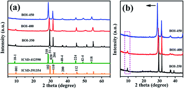
Fig. 1 shows the XRD patterns of the as-prepared bismuth oxyiodide (BOI) samples. As shown in Fig. 1a, every XRD pattern has a similar peak curve; all the observed peaks of BOI-350 can be indexed to tetragonal BiOI (JCPDS no. 10-0445 and ICSD-391354) and no other residual phase, such as BiI3, is detected. This indicates that BOI-350 is pure BiOI.38 Similarly, according to the major diffraction peaks at 28.68°, 31.29°, 37.11°, 45.04°, 49.20°, and 54.22°, the XRD pattern of BOI-450 can be indexed to monoclinic Bi4O5I2 (ICSD-412590). For BOI-400, there is no single crystal structure matching its diffraction peaks well except orthorhombic Bi3O4Br (JCPDS no. 84-0793). Since no reactant that contains Br was used in the synthesis process, BOI-400 could be only attributed to the mixed phase of BiOI and Bi4O5I2.39 For the sake of comparing and analyzing the difference in the crystal structures of the three BOI samples further, partial enlargement XRD patterns were acquired (Fig. 1b). It is noticed that (marked with an arrow) the main double peaks located between 25° and 35° shift to smaller angles with the gradual increase in the calcination temperature. Besides, along with the angle deviation, the weak peak at 9.5° disappears as well, as denoted in the dotted box. All the phenomena mentioned above indicate that the heat-treatment process plays an important role in the conversion and formation of new crystal structures.3.2 TG analysis
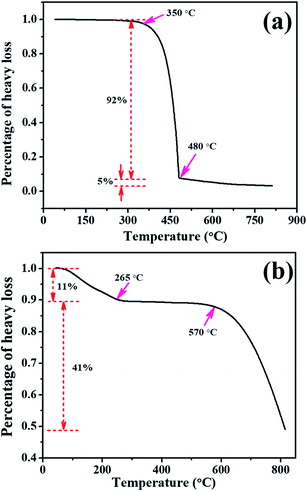
To further demonstrate this conclusion and explore the reaction mechanism, TGA was carried out to determine the phase transformation details of the BOI samples in the annealing process. Fig. 2a displays the TGA curve of bulk BiI3 in an air flow. It is found that there is no obvious change in BiI3 for temperatures below 300 °C. However, when the temperature reaches 350 °C, a dramatic weight loss is observed. From 350 °C to 480 °C, the total weight loss of bulk BiI3 is up to 92%, which means that the bulk BiI3 is completely changed when calcination is continued. With the further increase in the temperature, the weight loss of BiI3 is sustained but only 5%. At the end of the heating process, no more weight loss appears, and the reaction residue becomes stable.Fig. 2b shows the TGA curve of bulk BiI3 in an N2 flow. As shown in Fig. 2b, the first 11% weight loss occurs between room temperature and 265 °C, and this can be attributed to the dehydration of BiI3. As the temperature rises, almost no weight loss occurs from 265 °C to 550 °C, which means that the bulk BiI3 is very stable in this temperature range. However, with the heat treatment proceeding, a significant weight loss occurs after 550 °C and continues until the process ends. This calcination behaviour of BiI3 is distinct from its previous performance in an air flow, indicating that oxygen is critical to the formation of the as-prepared BOI samples. The total weight loss of the above-mentioned stages is about 52%. Considering that the melting point and boiling point of BiI3 are 408.6 °C and 542 °C, respectively, the weight loss behaviour of BiI3 in an N2 flow is in good agreement with the following reaction eqn (1):
| 2BiI3 → Bi2 + 3I2↑ | (1) |
| BiI3 + O2 → BiOI + I2↑ | (2) |
| 2Bi + O2 + I2 → 2BiOI | (3) |
| 8BiOI + O2 → 2Bi4O5I2 + 2I2↑ | (4) |
| 2Bi4O5I2 + O2 → 4Bi2O3 + 2I2↑ | (5) |
Because of the lower melting point, I2 will first evaporate completely and when this is finished, the total weight loss of reaction (1) is about 55%, which matches well with the data in Fig. 2b.
According to the analyzed results of the XRD patterns and TGA curves, the formation process of the as-prepared BOI samples can be concluded as per the above-mentioned reaction eqn (2)–(5).
In reaction (2), BiI3 reacts with oxygen first and generates rust-red BiOI and iodine vapor. In reaction (3), Bi generated from the BiI3 decomposition continues to react with oxygen and iodine vapor to form BiOI. As the reaction proceeds, the formed BiOI is oxidized by oxygen steadily and produces yellow Bi4O5I2 and iodine vapor, as shown by reaction (4). In reaction (5), the prepared Bi4O5I2 reacts with oxygen further and finally generates stable Bi2O3 and iodine vapor. Then, the residual mass of the whole system changes slightly.
3.3 SEM and TEM analyses
The morphology and microstructure of the as-prepared BOI samples were further investigated by SEM and TEM. Fig. 3 shows the SEM images of the BOI samples. It can be seen that all the three samples consist of individual but mutually overlapping nanosheets, and some of these nanosheets possess perfect right angles. Fig. 3d shows the theoretical crystal structures of the as-prepared BOI samples. According to the XRD patterns mentioned above, during the calcination of bulk BiI3, the first generated sample was BiOI with a tetragonal crystal structure and under certain conditions, tetragonal BiOI preferred to form a two-dimensional (2D) sheet-like structure. Because the subsequent reactions were just the oxidation of BiOI and the release of iodine vapor on the macro scale, the 2D sheet-like structure of BiOI survived on the micro scale and all the BOI samples retained this sheet-like structure. Thus, in this regard, the XRD and SEM results match each other well.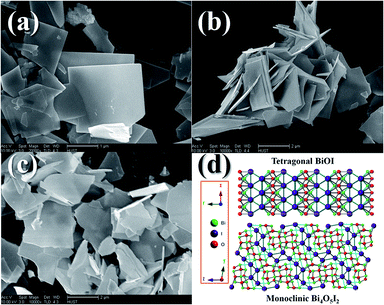 | ||
| Fig. 3 SEM images and theoretical crystal structures of the BOI samples: (a) BOI-350; (b) BOI-400; (c) BOI-450; (d) crystal structures of BiOI and Bi4O5I2. | ||
Fig. 4 shows the typical TEM images and selected area electron diffraction (SAED) patterns of the BOI samples. As shown in Fig. 4, all three BOI samples are composed of nanosheets with right angles. This situation is in accordance with the SEM results. The SAED patterns of BOI-350, BOI-400 and BOI-450 are displayed in Fig. 4c, f and i, respectively. It is obvious that all the three SAED patterns, taken from different crystal zone axes, exhibit similar diffraction spots array, which means these samples are all single crystals. However, unlike the smooth surface of the BOI-350 nanosheets, the surface of the BOI-400 nanosheets is more rough and full of suspected nanopore traces, as shown in Fig. 4d and the dashed box pointed in Fig. 4e. Likewise, nanopores are found on the BOI-450 nanosheets too; the difference is that the nano-pores on BOI-450 are more apparent with a mean diameter of 10 nm and run through and fill the whole nanosheets, as shown in Fig. 4g and e. This structure is very special and fascinating and for further confirmation, nitrogen adsorption/desorption measurements are obtained. As shown in Fig. 5, the BTO-450 sample has a typical type-IV isotherm characteristic of a mesoporous structure and a high BET area of 339 m2 g−1. The average size of the mesopores of BTO-450 was 9.2 nm, which was in agreement with the TEM observations (the inset in Fig. 5).
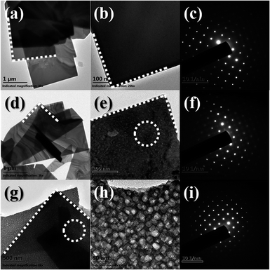 | ||
| Fig. 4 TEM images and electronic diffraction patterns of BOI samples: (a–c) BOI-350; (d–f) BOI-400; (g–i) BOI-450. | ||
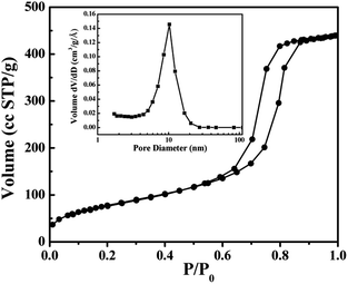 | ||
| Fig. 5 Nitrogen-adsorption/desorption isotherms and pore size distributions (inset) of the BOI-450 sample. | ||
3.4 Formation mechanism analysis
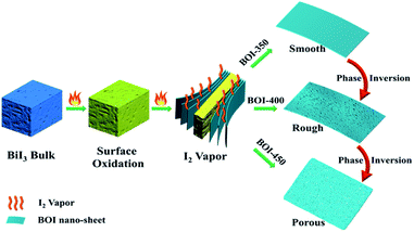
According to the above-mentioned conclusions, the formation mechanism of these novel mesoporous BOI single-crystal nanosheets is shown in Fig. 6. At the first stage, with the reaction temperature rising, two main reactions proceed. In the first one, the surface of bulk BiI3 starts to oxidize and generates BiOI and I2 vapor (see chemical eqn (2)). In the second one, the internal of bulk BiI3 begins to decompose in a hypoxia state and generates Bi and I2 vapor (see chemical eqn (1)). Different from the surface-formed I2 vapor that is easy to run off, the internally formed I2 vapor is sealed by the BiOI shells and is hard to release. However, as the internal I2 vapor continuously accumulates to a certain pressure, it will break and strip the surface-generated BiOI shells from the BiI3 bulk layer by layer and then, the BiOI single-crystal nanosheets are obtained. At 400 °C, the generated BiOI nanosheets are oxidized by oxygen further along with the formation of I2 vapor (see chemical eqn (4)). In this step, the locations occupied by I atoms in the BiOI crystal structure are vacated, leaving nanopore traces on the nanosheet surface when the I2 vapor is released from BiOI. At 450 °C, the higher temperature accelerates the recrystallization of BiOI and the evaporation of the I2 vapor from the outside to the inside of BiOI, leading to the formation of Bi4O5I2 microsheets with a mass of densely distributed nano-pores running through and filling the whole nanosheets, as shown in Fig. 6.3.5 UV-vis diffuse reflectance spectral analysis
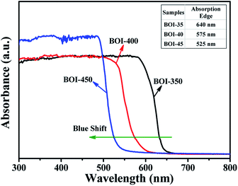
The optical properties of the as-prepared BOI samples are investigated by UV-vis diffuse reflectance spectroscopy (DRS) (Fig. 7). All the three samples exhibit strong absorption in both visible and ultraviolet ranges. BOI-350 has the maximal absorbance wavelength and its absorption edge is 640 nm, which is in agreement with a previous result.40 The absorption edges of BOI-400 and BOI-450 are 575 nm and 525 nm, respectively. As the arrow shows in Fig. 7, there is an apparent blue shift in the absorption edge of the samples on increasing the annealing temperature, indicating that bulk BiI3 has been transformed thoroughly. More remarkably, the absorption strength of BOI-450 in the range of 300–500 nm is higher than that of both BOI-350 and BOI-400, implying that BOI-450 may possess better catalyst activity.41,423.6 Photocatalytic activity analysis
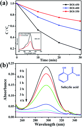
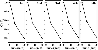
To evaluate practicability, the as-prepared BOI nanosheets are successfully employed to catalyze the removal of RhB and salicylic acid pollutants in water driven by visible light. As shown in Fig. 8a, after adsorption for 12 h in the dark, the as-prepared BOI-450 sample exhibits the best activity, and RhB can be degraded thoroughly in 30 min. Although the visible light absorption range of BOI-450 is narrower than that of both BOI-350 and BOI-400, its excellent photocatalysis ability obviously benefits from other advantages such as higher porosity (inset in Fig. 8a). For a qualified and effective catalyst, high contact capacity with the reactants is necessary. Thus, obviously, due to the porous nature of BOI-450, it has this quite remarkable ability. In order to make it more pertinent, we choose BOI-450 as the key target in the following test. For a further demonstration, another colorless pollutant salicylic acid is also used. Fig. 8b shows the corresponding UV-vis spectrum for the change in salicylic acid versus time. As shown in Fig. 8b, the 296 nm peak of salicylic acid can be reduced gradually in 4 h, indicating that BOI-450 indeed has excellent photocatalytic activity.The durability of the BOI-450 sample was also tested by the degradation of RhB under visible light irradiation. As shown in Fig. 9, BOI-450 exhibits excellent stability and maintains similar photocatalytic activity after five reaction runs. Since the active component loss of the photocatalyst cannot be avoided in the recycling tests, the tiny decrease in the degradation rate of RhB is reasonable.
4. Conclusions
In summary, a novel 2D sheet-like bismuth oxyiodide single-crystal functional material with numerous mesopores was synthesized by a simple and mild heat-treatment approach. The average diameter of these pores was 9.2 nm. It was found that the formation of the as-prepared BOI nanosheets was a temperature- and reaction time-dependent process and involved crystal structure transformation. It was also demonstrated that the element I in the BOI system played an essential role in generating the 2D porous structure. Owing to this special 2D porous structure, BTO-450 displayed great activities and good stability in catalyzing RhB and salicylic acid mineralization under visible light irradiation. The 2D mesoporous structure is beneficial to enhance the contact capacity of the catalysts with the reactants, thereby improving their reaction efficiency.Conflicts of interest
There are no conflicts of interest to declare.Acknowledgements
This work was supported by the Natural Science Foundation of China (no. 51802223), the Project Funded by China Postdoctoral Science Foundation (2016T90689, 2015M580642).References
- M. Chhowalla, H. Shin, G. Eda, L. Li, K. Loh and H. Zhang, Nat. Chem., 2013, 5, 263 CrossRef PubMed.
- J. Coleman, M. Lotya, A. O'Neill, S. Bergin, P. King, U. Khan and K. Young, Science, 2011, 331, 568 CrossRef CAS PubMed.
- S. Butler, S. Hollen, L. Cao, Y. Cui, J. Gupta, H. Gutierrez, T. Heinz, S. Hong and J. Huang, ACS Nano, 2013, 7, 2898 CrossRef CAS PubMed.
- X. Quan, Y. Jia and J. Mietek, Chem. Soc. Rev., 2012, 41, 782 RSC.
- S. Sasha, D. Dmitriy, D. Geoffrey, K. Kevin, Z. Eric, S. Eric, P. Richard, N. SonBinh and R. Rodney, Nature, 2006, 442, 282 CrossRef PubMed.
- H. Zhang, C. Liu, X. Qi, X. Dai, Z. Fang and S. Zhang, Nat. Phys., 2009, 5, 438 Search PubMed.
- M. Xu, T. Liang, M. Shi and H. Chen, Chem. Rev., 2013, 113, 3766 CrossRef CAS PubMed.
- Q. Han, B. Wang, J. Gao, Z. Cheng, Y. Zhao, Z. Zhang and L. Qu, ACS Nano, 2016, 10, 2745 CrossRef CAS PubMed.
- T. Su, Q. Shao, Z. Qin, Z. Guo and Z. Wu, ACS Catal., 2018, 8, 2253 CrossRef CAS.
- M. Guan, C. Xiao, J. Zhang, S. Fan, R. An, Q. Cheng, J. Xie, M. Zhou, B. Ye and Y. Xie, J. Am. Chem. Soc., 2013, 135, 10411 CrossRef CAS PubMed.
- Y. Huo, J. Zhang, M. Miao and Y. Jin, Appl. Catal., B, 2012, 111–112, 334 CrossRef CAS.
- T. Zhu, Z. Wang, S. Ding, J. Chen and X. Lou, RSC Adv., 2011, 1, 397 RSC.
- W. Qing, K. Kourosh, K. Andras, C. Jonathan and S. Michael, Nat. Nanotechnol., 2012, 7, 699 CrossRef PubMed.
- B. Francesco, C. Luigi, Y. Gui, S. Meryl, T. Valentina, F. Andrea, R. Rodney and P. Vittorio, Science, 2015, 347, 41 Search PubMed.
- B. Alexander, Nat. Mater., 2011, 10, 569 CrossRef PubMed.
- O. Painter, R. Lee, A. Scherer, A. Yariv, J. O'Brien, P. Dapkus and I. Kim, Science, 1999, 284, 1819 CrossRef CAS PubMed.
- S. Sarma, Rev. Mod. Phys., 2011, 83, 407 CrossRef.
- K. Novoselov, A. Mishchenko, A. Carvalho and A. Castro, Science, 2016, 353, 461 CrossRef CAS PubMed.
- F. Koppens, T. Mueller, Ph. Avouris, A. Ferrari, M. Vitielloand and M. Polini, Nat. Nanotechnol., 2014, 9, 780 CrossRef CAS.
- Y. Zheng, W. Xu, H. Ya, P. Xin, Z. Zong and Q. Jie, Carbon, 2017, 117, 376 CrossRef.
- Z. Jian, X. You, Z. Yuan, F. Tian, W. Jie, M. Sheng and X. Li, Carbon, 2016, 107, 638 CrossRef.
- Y. Fan, X. Xiang, P. Hong, Y. Hua, D. Yan, L. Wen, Y. Jia, S. Qi and W. Xiang, Appl. Catal., A, 2015, 507, 109 CrossRef.
- S. Leng, C. Ming, R. Tie and Y. Zhong, J. Power Sources, 2015, 274, 791 CrossRef.
- A. Tarek, S. Osama, W. Jonas and M. Anja, J. Mater. Chem., 2012, 22, 18252 RSC.
- A. Corma, Chem. Rev., 1997, 97, 2373 CrossRef CAS PubMed.
- M. Davis, Nature, 2002, 417, 813 CrossRef CAS PubMed.
- X. Xiang, L. Lin, Y. Fan, P. Hong, F. Xiu and W. Xiang, Mol. Catal., 2017, 441, 81 CrossRef.
- E. Richman, T. Brezesinski and S. Tolbert, Nat. Mater., 2008, 7, 712 CrossRef CAS PubMed.
- L. Hwan, R. Amaranath, K. Praveen, L. Manho and K. Tae, Appl. Surf. Sci., 2019, 494, 239 CrossRef.
- M. Xing, F. Huan, L. Chun, L. Xiao, Z. Fan and W. Yong, J. Mater. Sci. Technol., 2017, 33, 1067 CrossRef.
- Z. Yong, L. Zheng, N. Sina, A. Pulickel and L. Jun, Small, 2012, 8, 966 CrossRef PubMed.
- T. Alammar, O. Shekhah, J. Wohlgemuth and A. Mudring, J. Mater. Chem., 2012, 22, 18252 RSC.
- L. Ye, L. Tian, T. Peng and L. Zan, J. Mater. Chem., 2011, 21, 12479 RSC.
- S. Sun, W. Wang, L. Zhang, L. Zhou, W. Yin and M. Shang, Environ. Sci. Technol., 2009, 43, 2005 CrossRef CAS PubMed.
- W. Lee, C. Lu, C. Chuang, Y. Chen, J. Fu, C. Siao and C. Chen, RSC Adv., 2015, 5, 23450 RSC.
- R. Yin, Y. Li, K. Zhong, H. Yao, Y. Zhang and K. Lai, RSC Adv., 2019, 9, 4539 RSC.
- J. Hou, J. Tang, K. Feng, F. Idrees, M. Tahir, X. Sun and X. Wang, Mater. Lett., 2019, 252, 106 CrossRef CAS.
- X. Xiao, C. Xing, G. He, X. Zuo, J. Nan and L. Wang, Appl. Catal., B, 2014, 148–149, 154 CrossRef CAS.
- C. Chun, Y. Huan, M. Wei, C. Yan, W. Li, Y. Li and Q. Hong, Appl. Catal., B, 2019, 254, 647 CrossRef.
- J. Hu, S. Weng, Z. Zheng, Z. Pei, M. Huang and P. Liu, J. Hazard. Mater., 2014, 264, 293 CrossRef CAS PubMed.
- C. Yu, G. Li, S. Kumar, K. Yang and R. Jin, Adv. Mater., 2014, 26, 892 CrossRef CAS PubMed.
- T. Jamil, E. Mansor and M. El-Liethy, J. Environ. Chem. Eng., 2015, 3, 2463 CrossRef CAS.
Footnote |
| † Hang Liu and Jian Cai contributed equally. |
| This journal is © The Royal Society of Chemistry 2020 |

