 Open Access Article
Hollow Au@TiO2 porous electrospun nanofibers for catalytic applications†
Labeesh Kumar‡
a,
Sajan Singh‡a,
Andriy Horechyy b,
Petr Formanekb,
René Hübnerc,
Victoria Albrechtb,
Janek Weißpflogb,
Simona Schwarzb,
Puhup Puneeta and
Bhanu Nandan
 *a
*a
aDepartment of Textile Technology, Indian Institute of Technology Delhi, Hauz Khas, New Delhi 110016, India. E-mail: nandan@textile.iitd.ac.in
bLeibniz-Institut für Polymerforschung Dresden e.V., Hohe Strasse 6, Dresden 01069, Germany
cInstitute of Ion Beam Physics and Materials Research, Helmholtz-Zentrum Dresden-Rossendorf, Bautzner Landstrasse 400, 01328 Dresden, Germany
First published on 12th February 2020
Abstract
Catalytically active porous and hollow titania nanofibers encapsulating gold nanoparticles were fabricated using a combination of sol–gel chemistry and coaxial electrospinning technique. We report the fabrication of catalytically active porous and hollow titania nanofibers encapsulating gold nanoparticles (AuNPs) using a combination of sol–gel chemistry and coaxial electrospinning technique. The coaxial electrospinning involved the use of a mixture of poly(vinyl pyrrolidone) (PVP) and titania sol as the shell forming component, whereas a mixture of poly(4-vinyl pyridine) (P4VP) and pre-synthesized AuNPs constituted the core forming component. The core–shell nanofibers were calcined stepwise up to 600 °C which resulted in decomposition and removal of the organic constituents of the nanofibers. This led to the formation of porous and hollow titania nanofibers, where the catalytic AuNPs were embedded in the inner wall of the titania shell. The catalytic activity of the prepared Au@TiO2 porous nanofibers was investigated using a model reaction of catalytic reduction of 4-nitrophenol and Congo red dye in the presence of NaBH4. The Au@TiO2 porous and hollow nanofibers exhibited excellent catalytic activity and recyclability, and the morphology of the nanofibers remained intact after repeated usage. The presented approach could be a promising route for immobilizing various nanosized catalysts in hollow titania supports for the design of stable catalytic systems where the added photocatalytic activity of titania could further be of significance.
Introduction
Colloidal nanocatalysts have received significant interest due to their fascinating optical as well as electronic properties, principally, because of their large surface area to mass ratio.1–3 Such nanocatalysts have been extensively used as effective catalysts for a number of catalytic reactions. However, there are numerous technical challenges associated with the usage of nanocatalysts, which limit their extensive applications.4–6 The first concern is the poor stability of the nanometer-sized catalysts due to their high surface energy. Hence, during the catalytic reactions, the nanocatalysts tend to aggregate or re-shape which makes their dispersion difficult. The second challenge is the difficulty in separation and recovery of the nanocatalysts due to their extremely small size. This not only hinders the reusability of the nanocatalysts but also creates environmental hazards.In order to overcome these crucial challenges associated with the practical usage of the nanocatalysts, a number of immobilization approaches have been reported using solid supports.7–9 Among the various solid supports investigated, the use of porous substrates as a support has been shown to be the most promising one. In the past, various porous supports such as mesoporous metal oxides (silica, titania, etc.),10–12 microporous zeolites, cellulose membranes etc.8,9,13–18 have been used to host the nanocatalysts. In this case, it is crucial that the catalyst is strongly bound to the support surface in order to ensure its long-term stability and reusability.8 However, it has been found that the increased adhesion strength between the catalyst and the solid supporting the substrate also decreases the active surface area leading to a significant reduction in the intrinsic catalytic activity of the nanocatalyst. The use of porous hollow supports, which has a reactant-permeable shell with the catalyst enclosed inside, are more innovative supports, which may overcome some of the challenges associated with the simple catalyst-on-support kind of systems. Some of the principal examples of such supports are the yolk–shell (single-core) or nanorattles (movable cores) type of systems.19 In these cases, the catalytic reaction occurs on the surface of the catalyst which are located inside the cavity or attached to the inner wall of the shell. The design of these support systems ensures that the aggregation and mechanical leaching of the catalyst during the reaction is negligible. Furthermore, such core–shell and yolk–shell catalytic systems were found to be quite stable under harsh conditions and, hence, are more suitable for high-temperature catalytic reactions.9,20,21 However, the main drawback is that the large-scale preparation of the yolk–shell catalytic systems is challenging and, hence, it may not find its way into practical applications.
In the last few years, electrospinning has been acknowledged as a versatile approach for fabricating solid porous fibrous supports for nanocatalysts. The electrospinning process is simple, economical, and scalable, where the diameter of the nanofibers could be easily tuned. Furthermore, a range of polymers and composite materials can be easily processed into nanofibers using this method. So far, most of the work on electrospun catalytic supports has dealt with the surface functionalization of the electrospun nanofibers with the nanocatalyst.22–25 In this case, the electrospun nanofibers provide a very high surface area for the necessary catalytic sites. Moreover, the inherent porous nature of the non-woven structure formed from the electrospun nanofibers allows it to be used as efficient catalytic membranes.23,24 The electrospinning approach also enables the formation of hollow nanofibers, using coaxial or emulsion electrospinning, which could provide a marked enhancement in the total surface area available. However, limited work has been done on the fabrication of such hollow nanofibers for the use as catalytic supports so far. The hollow nanofibers fabricated were either as such catalytically active (such as those based on metal oxides) or the catalytic nanoparticles were incorporated into the porous shell of the nanofibers.26 However, the entrapment of the nanocatalyst within the shell is expected to mask the potential catalytic sites available on the nanocatalyst thereby reducing the total active surface area.
This issue could be solved if the nanocatalysts are trapped inside the hollow core of the nanofibers. In this case, the nanocatalyst was expected to be bound to the inner surface of the nanofiber shell only through a small fraction of its total surface area such that most of the active surface area will be available for catalysis. In the present work, we demonstrate the fabrication of such a catalytic system via coaxial electrospinning approach. The catalytic system consisted of hollow titania nanofibers with gold nanoparticles (AuNPs) entrapped in the hollow core. It will be shown that the system exhibited excellent catalytic activity as well as reusability.
Experimental
Materials
Poly(4-vinyl pyridine) (P4VP) (average Mw ∼ 160![[thin space (1/6-em)]](https://www.rsc.org/images/entities/char_2009.gif) 000 g mol−1), poly(vinyl pyrrolidone) (PVP) (average Mw ∼ 1
000 g mol−1), poly(vinyl pyrrolidone) (PVP) (average Mw ∼ 1![[thin space (1/6-em)]](https://www.rsc.org/images/entities/char_2009.gif) 300
300![[thin space (1/6-em)]](https://www.rsc.org/images/entities/char_2009.gif) 000), gold(III) chloride hydrate (HAuCl4·3H2O, 99.9%, trace metals basis), trisodium citrate dihydrate (C6H5Na3O7·2H2O, ≥99%), acetic acid (CH3COOH, ≥99.7%), Congo red (CR, 85%), sodium borohydride (NaBH4, ≥96%) were procured from Sigma-Aldrich and used as reactants without further purifications. Titanium(IV) isopropoxide (TIP) and 4-nitrophenol (4-NP) were purchased from Spectrochem Chemicals. Ethanol and N,N-dimethyl formamide (DMF) were procured from Merck and Fisher Scientific, respectively.
000), gold(III) chloride hydrate (HAuCl4·3H2O, 99.9%, trace metals basis), trisodium citrate dihydrate (C6H5Na3O7·2H2O, ≥99%), acetic acid (CH3COOH, ≥99.7%), Congo red (CR, 85%), sodium borohydride (NaBH4, ≥96%) were procured from Sigma-Aldrich and used as reactants without further purifications. Titanium(IV) isopropoxide (TIP) and 4-nitrophenol (4-NP) were purchased from Spectrochem Chemicals. Ethanol and N,N-dimethyl formamide (DMF) were procured from Merck and Fisher Scientific, respectively.
Synthesis of AuNPs
AuNPs were synthesized following Brown's method. In a typical synthesis, 1 mL of 5 mM HAuCl4 solution was dissolved in 9 mL of deionized water. After 1 minute, 220 μL of 1 wt% sodium citrate was added dropwise in the solution. Finally, 110 μL of freshly prepared ice-cold 0.08% NaBH4 solution was added. After another 10 minutes of stirring, the solution was subsequently cooled down to room temperature.27,28Preparation of core and shell solutions
Firstly, the core-forming and shell-forming solutions for coaxial electrospinning were prepared separately. To prepare core-forming P4VP + AuNPs solution in DMF, citrate stabilized AuNPs were collected using centrifugation, vacuum dried to get water free AuNPs, and then re-dispersed in 1 mL of DMF. The core-forming solution was prepared by dropwise mixing of DMF solubilized AuNPs with 4 mL of 0.2 g mL−1 P4VP solution in DMF.29,30 The shell-forming solution was prepared in order to produce a porous titania shell. For this, 0.3 g PVP was dissolved in 5 mL of ethanol in a round-bottom flask. Subsequently, 3 mL of titanium(IV) isopropoxide (TIP) and 1 mL of acetic acid were injected one after another under constant stirring. The solution was stirred further for an hour.31 The calculated weight fraction of Au in electrospun Au@TiO2 nanofibers after pyrolysis was estimated as ca. 0.12 wt% relative to the TiO2 (see also ESI† for more details).Fabrication of Au@TiO2 nanofibers
Firstly, the core–shell electrospun nanofibers were fabricated using a coaxial electrospinning approach. For this, the AuNPs + P4VP and TIP + PVP solutions were taken in core and shell syringe pumps, respectively. The tip to collector distance was set to 20 cm, and a voltage of 25 kV was applied. The flow rates were adjusted to 1.7 and 3 mL h−1 for the core and shell parts, respectively, to obtain uniform bead free nanofibers. The as-prepared core–shell nanofibers were further calcined via thermal treatment to obtain Au@TiO2 nanofibers. To this end, the core–shell nanofibers were first heated stepwise in a muffle furnace from room temperature to 300 °C with a temperature ramp rate of 5 °C min−1 and held for 30 min. The temperature then was raised from 300 °C to 600 °C and the samples were further held at this temperature for 4 hours. During heat treatment, the polymeric components of the nanofibers was removed such that hollow nanofibers comprising mesoporous titania shell are formed. The removal of P4VP from the cores leaves behind AuNPs in the hollow core. For comparison of the catalytic efficiency, solid titania and hollow titania nanofibers without AuNPs were also prepared using the TIP + PVP solution.Characterization
Samples' surface morphology was observed under a ZEISS EVO 18 scanning electron microscope (SEM). Before observation, samples were coated with a thin layer of carbon to avoid the accumulation of electrons on the sample's surface. High-resolution electron microscopy images were obtained using a Tecnai G2 transmission electron microscope (TEM, Thermo Fischer Scientific/FEI, USA) operated at 200 kV. The samples for TEM analysis were prepared on a copper grid. High-angle annular dark-field scanning transmission electron microscopy (HAADF-STEM) and spectrum imaging analysis based on energy-dispersive X-ray spectroscopy were conducted with a Talos F200X (Thermo Fischer Scientific/FEI, USA) operated at 200 kV and equipped with a Super-X EDX detector to confirm the presence of AuNPs inside the nanofibers. The crystalline nature of titania was investigated using X-ray diffraction (XRD) analysis performed on a PANalytical X'Pert3 powder diffractometer. N2 adsorptions experiments at the temperature of liquid nitrogen (77 K) were carried out employing the automatically working sorptiometer Autosorb-1 (Quantachrome GmbH and Co. KG, USA) which is a volumetrically operating instrument. The evaluation of the specific surface area was performed according to Brunauer, Emmett, and Teller (BET) method. Pore size distribution was determined according to the Barrett–Joyner–Halenda (BJH) method for mesopores. UV-Vis measurements were carried out on UV-2450 Shimadzu UV-Vis spectrometer. The content of gold in Au@TiO2 nanofibers was determined by using an Inductively Coupled Plasma-Optical Emission Spectrometer (ICP-OES) iCAP 7400 from Thermo Scientific™ (Dreieich, Germany) using the Qtegra™ Intelligent Scientific Data Solution™ software. For the ICP-OES measurement, the Au@TiO2 catalyst samples were digested in 10 mL of aqua regia solution for 1 hour under boiling conditions. A further extension of digesting time did not result in higher gold content. The dissolved gold was collected from the dispersion using a 0.25 μm PTFE filter, and this solution was diluted to five different concentrations, which were subjected to ICP-OES to measure the amount of gold in the Au@TiO2 nanofibers. Each sample was measured three times. Fresh standards were prepared to construct a calibration curve using five calibration points: 1, 5, 10, 50, and 100 mg L−1 of gold purchased from Bernd Kraft GmbH (Duisburg, Germany).Measurements of catalytic activity
The Au@TiO2 hollow nanofibrous catalyst was dispersed in Millipore water using the ultrasonic bath to give stock dispersion with the catalyst concentration of 0.075 mg mL−1. Next, 12 mL of catalyst dispersion was added to a mixture of freshly prepared aqueous solution of NaBH4 (18 mL, 0.2 M), aqueous solution of 4NP (6 mL, 0.2 mM) and Millipore water (8 mL), such that the total volume of the reaction mixture in all experiments was kept constant (44 mL). Successive UV-Vis spectra of filtered (through 0.25 μm PTFE) aliquots were recorded in the wavelength range 250–900 nm immediately after the addition of the catalyst. The evaluation of the reaction kinetics was done by monitoring the intensity change of the nitrophenolate absorption peak (λmax = 400 nm) with respect to the time.32–34 For recyclability analysis, 27 times more Au@TiO2 catalyst was used in the reaction solution, and after complete reduction, the catalyst was collected by using a detachable filter assembly and reused by maintaining the same conditions as before.35 Experimental conditions and reagent concentrations during the catalytic degradation of Congo red dye were maintained similar to those used for 4-NP reduction.Results and discussion
Fig. 1 shows a schematic illustration of the preparation of Au@TiO2 hollow nanofibers. In the first step, the core–shell nanofibers were spun using coaxial electrospinning. Here, the TIP + PVP constituted the shell of the nanofibers, whereas AuNPs dispersed in PVP or P4VP constituted the core material. In the next step, the core–shell nanofibers were calcined at high temperatures in an oxidative atmosphere. This resulted in the removal of the organic constituents of the nanofibers and the formation of the porous shell with hollow interiors, where the AuNPs plausibly were embedded in the inner wall of hollow and porous titania nanofibers.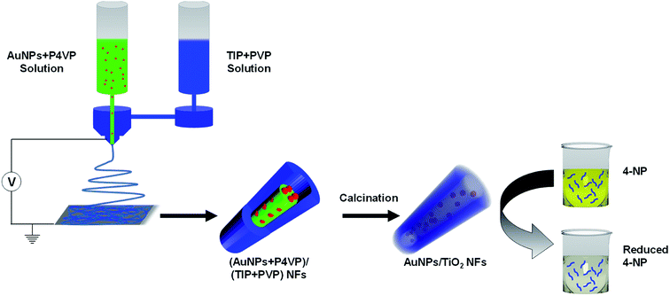 | ||
| Fig. 1 Schematic illustration of the preparation of Au@TiO2 hollow nanofibers and their application for catalytic reduction of 4-NP. | ||
The synthesized nanocatalyst, i.e., the AuNPs, were firstly characterized using UV-Vis spectroscopy and TEM, as shown in Fig. 2a and b respectively. The characteristic plasmon absorption peak of the AuNPs was observed at 520 nm in the UV-Vis spectra. Furthermore, the TEM images showed spherical AuNPs with an average diameter of 8 nm. The synthesized AuNPs subsequently were mixed with the P4VP solution in DMF, and the resulting AuNP + P4VP solution was used as the core fluid during coaxial electrospinning process.
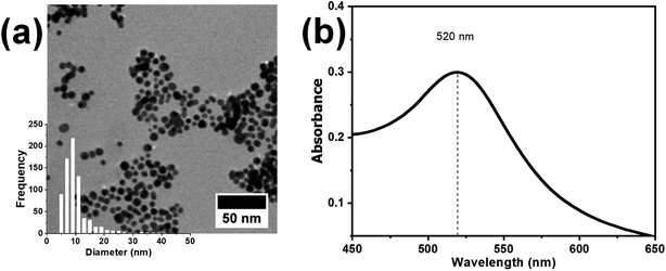 | ||
| Fig. 2 (a) TEM image and (b) UV-visible spectrum of the as-synthesized AuNPs. The inset in the bottom left corner (a) shows the size distribution plot of the synthesized AuNPs. | ||
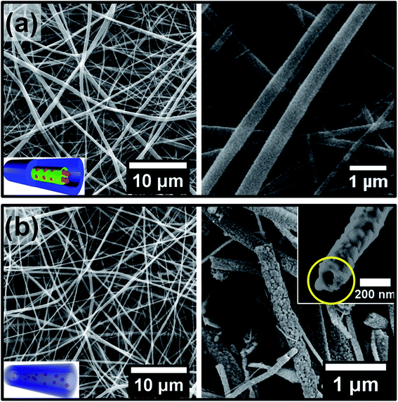
Next, the coaxial electrospinning was performed using the TIP + PVP solution as the shell-forming component and the P4VP + AuNP mixture solution as the core-forming component. The electrospinning parameters were optimized in order to obtain bead-free uniform core–shell nanofibers (see ESI, Fig. S3†). Furthermore, the flow rates of the core- and shell-forming solutions were chosen so that the thickness of the titania shell could be minimized to provide an easy pathway for the reactants and products to diffuse in and out of the hollow nanofibers during the catalytic reaction. Fig. 3a shows SEM images of the nanofibers obtained at the optimized electrospinning conditions, where the shell and core flow rates were kept at 3.0 and 1.7 mL h−1, respectively. These core–shell nanofibers were subsequently calcined at 600 °C. Fig. 3b shows the nanofiber morphology after the calcination step. The SEM results clearly reveal that the fibrous structure of the core–shell nanofibers was retained after calcination. Moreover, the diameter of the nanofibers before and after calcination were found to be nearly the same. This clearly indicates that the shrinkage of the nanofibers was minimal which is crucial for retaining the hollow core during the removal of P4VP on calcination. Furthermore, SEM images of the nanofiber tips also revealed a hollow core, as shown in the right inset of Fig. 3b.
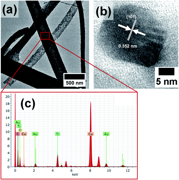
However, the AuNPs which were likely to be present in the hollow core were not observed in the SEM images, as they were masked by the titania shell. Hence, the morphology and composition of the calcined nanofibers were further analyzed by TEM and EDX measurements. The TEM images in Fig. 4a and b show the formation of titania nanofibers and provide evidence for the polycrystalline nature of the titania shell. Furthermore, the presence of AuNPs was revealed from TEM-EDX measurements. In particular, the EDX spectrum in Fig. 4c shows the prominent Au Lα peak at 9.71 keV and the Mα peak at 2.12 keV. Furthermore, the presence of AuNPs in the hollow titania nanofibers was also confirmed by STEM analyses (Fig. 5).36,37 The combination of HAADF-STEM imaging and EDX-based element mapping clearly showed the presence of AuNPs trapped in the titania shell of the nanofibers. Furthermore, the HRTEM image shown in Fig. 4b clearly revealed the crystalline nature of the titania shell with an interlayer distance of 0.352 nm which matches well with the lattice spacing corresponding to the (101) lattice planes of anatase TiO2.38–40
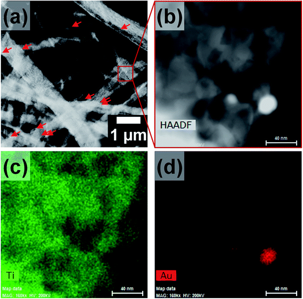 | ||
| Fig. 5 (a) and (b) HAADF-STEM micrographs of Au@TiO2 nanofibers as well as (c) Ti and (d) Au element distributions obtained by EDX analysis. Scale bars are 40 nm. | ||
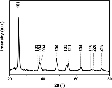
The crystalline nature of the titania shell was also examined using XRD, as shown in Fig. 6. The XRD pattern of the nanofibers showed diffraction peaks suggesting the polycrystalline character of the titania. The most intense peaks for the calcined titania nanofiber samples are seen at 2θ values of 25.6° and 48.5°, which corresponds to the (101) and (200) lattice planes, respectively. The presence of these peaks indicated that the titania is present in its anatase form.38,40 Furthermore, the broadening of the diffraction peaks revealed that the titania crystallites were small in size. The average crystallite size of the calcined hollow mesoporous TiO2 nanofibers from corresponding XRD peaks were determined using the well-known Scherer equation:41
Next, it was desirable that sufficient surface is available for access of the reactants to the nanocatalyst surface during the catalytic reaction. Hence, the specific surface area and pore size distribution of the Au@TiO2 hollow nanofibers were determined using N2 sorption experiments. Fig. 7a shows the N2 adsorption–desorption with a hysteresis loop which is characteristic for samples with mesopores. The pore size distribution using the method by Barrett, Joyner and Halenda (BJH) shows mesopores between 10–50 nm with a maximum from 20–30 nm (Fig. 7b). For the determination of the specific surface area, the Brunauer–Emmett–Teller (BET) multipoint method was used which gave a value of 14 m2 g−1. The mesoporous structure is useful in increasing the catalyst efficiency since reactant molecules get more access to come in contact with the nanocatalyst.43,44
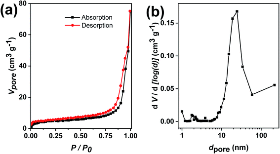 | ||
| Fig. 7 (a) N2 adsorption–desorption isotherms of Au@TiO2 nanofibers and (b) corresponding pore size distributions of mesopores. | ||
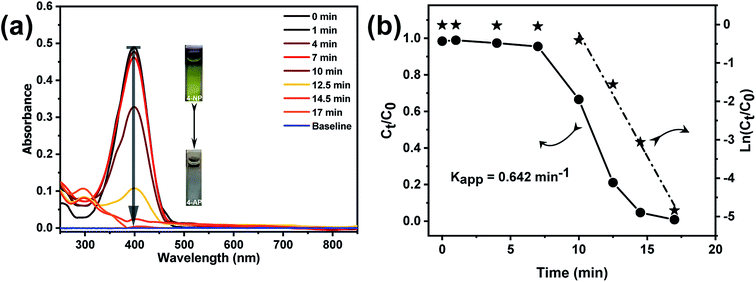
The catalytic efficiency of the Au@TiO2 hollow nanofibers was investigated by following the reduction of 4-nitrophenol with sodium borohydride as a model reaction.45–48 This reaction is well-known and is one of the most frequently used to evaluate the efficiency of various catalytic systems. It was also proved to produce only aminophenol without any side products so that reaction kinetics can be monitored by UV-Vis absorption spectral changes of 4-nitrophenolate versus time. Fig. 8a shows the time-resolved changes in the UV-Vis spectra during the borohydride reduction of 4NP in the presence of Au@TiO2 hollow nanofibers. The aqueous solution of 4-nitrophenol exhibits a strong absorption peak at 317 nm. Once the sodium borohydride is added in the solution, the absorption peak immediately shifts to 400 nm due to the formation of 4-nitrophenolate ion. After the addition of the Au@TiO2 hollow nanofibers, the intensity of nitrophenolate peak decreased, whereas the peak of 4-aminophenol at 300 nm, increased as the reaction proceeded. The degree of 4NP conversion (Ct/Co) was deduced from the UV-Vis spectra by monitoring the decrease of the absorption peak at 400 nm (At/Ao) with time. It is known that when the reaction is carried out in an excess of sodium borohydride, it follows pseudo-first order kinetics.45
Thus the apparent rate constant (Kapp), for the catalytic reaction studied, was determined from the slope of the linear plot ln(Ct/Co) versus time (Fig. 8b) and was found to be 0.642 min−1. However, the main problem with using the apparent rate constant for discussing the catalytic behavior is that even though it provides information about the efficiency of the nanocatalyst, the values cannot be directly compared with the Kapp values reported for other similar systems in the literature. Hence, it is necessary to carry out the normalization of the apparent rate constant in order to compare the catalytic efficiency with the other similar systems. The normalization of the rate constant could be done either with respect to the concentration or surface area of the catalyst. For concentration normalized rate constant, the weight or number of moles of the nanocatalyst could be used: Km = Kapp/mcat (where mcat is the number of moles of the catalyst).49,50 In the case of systems with different sizes of the catalyst, surface normalized rate constant Ks could also be used to characterize and compare the efficiency of the catalyst, where Ks = Kapp/Scat (Scat is the surface area of the nanocatalyst).51 Here, we determined the rate constants normalized both by the gold content (Km) and nanocatalyst surface area (Ks). From the ICP-OES analysis, the content of gold nanoparticles in the Au@TiO2 catalyst was determined as 0.094 wt% or 4.77 × 10⁻⁶ mmol mg−1 with respect to the total titania content. The surface area concentration of gold in the reaction solution was found to be 7.46 × 10⁴ m2 L−1 (All calculations are given in the ESI†). Subsequently, the normalized rate constants for this reaction were found to be: Km = 1.097 × 10⁵ s−1 mol−1 L and Ks = 14.34 s−1 m−2 L. The obtained result on the catalytic efficiency for 4NP reduction was comparable or even better than that reported for other supported AuNP catalytic systems.52–55
As titania itself is catalytically active, albeit, in the presence of light, the catalytic activity of neat titania nanofibers, as well as hollow titania nanofibers (i.e., both without embedded AuNP) was also evaluated under similar condition. In both cases, the conversion of 4NP to 4AP was negligible in the same time period, where the conversion was almost 99% in the presence of Au@TiO2 nanofibers (see Fig. S5a†). It must also be noted that the concentration of TiO2 nanofibers used in these experiments was almost 27 times higher than that in the case of Au@TiO2 hollow nanofibers. Hence, it could be safely argued that the catalytic behavior of the titania support had no significant influence on the catalytic efficiency of the Au@TiO2 catalyst observed. Thus, the high rate constant observed for the Au@TiO2 catalyst was intriguing considering also that the surface area of the nanofibers was not significantly high. As of now, the reasons for the high catalytic efficiency of the fabricated system here is not clear to us. However, recently it has been demonstrated that metal oxide supports alter electronic properties of AuNPs.56,57 Apart from, regular active sites, there are additional unique active sites with low coordinated gold atoms at contact edges between AuNPs and support.58,59 It has been further suggested via theoretical calculations that supports can play an important role in the activation of reactants bound to the gold nanoparticle surface.59 Hence, the enhanced catalytic reduction of 4-nitrophenol by gold nanoparticles attached to titania support can, therefore, plausibly be attributed to the presence of unique active sites at the gold–titania interface.60 Due to the porous and hollow morphology of the nanofibers, respectively several narrower and wider channels were formed, which served as mass transfer aisles for reactant and resultant. The reaction solution was flowed towards the inner surface of the nanofibers to react on active sites and form the resultant.61 The reduction of 4-nitrophenol occurred on the active sites of AuNPs which were located in the inner surface of hollow porous nanofibers. Electrons were released on diffusion and adsorption of borohydride ion (BH4−) on the active sites and electrons were captured by nitro (–NO2) group of the 4-nitrophenol. Furthermore, –H slowly replaced –O of the nitro group (–NO2) and form amine (–NH2) in aqueous conditions.61,62
The obtained results on 4NP reduction were compared in Table 1 with other analogous nanofibrous systems reported in literature till now.61,63,64 The Km value of our hollow Au@TiO2 nanofibrous catalyst is higher than the solid Au/TiO2 nanofibrous catalytic system reported by Hao et al.63 and Ning et al.64 and almost comparable to the hollow nanofibrous system reported by Yue et al.61
| Catalyst | Preparation | ω(Au) wt% | d(AuNP) (nm) | Kapp (s−1) | [Au]R (mol L−1) | Km (L s−1 mol−1) | Ref. |
|---|---|---|---|---|---|---|---|
| a HTHNF: hollow through-hole nanofibers, HTHNFs-L: HTHNFs with lower through-holes density, TNT: titania nanotube, UV: catalysis under ultraviolet light irradiation, ES: electrospinning, Co-ES: co-axial electrospinning, HT: hydrothermal method, ω(Au): weight% of Au in catalyst, d(AuNP): diameter of AuNPs in nm, [Au]R: molarity of Au in reaction mixture (mol L−1), Kapp: apparent rate constant in s−1, Km: normalized rate constant in L s−1 mol−1. | |||||||
| Au(2)/TiO2 NFs | ES | 1.97 | 10–30 | 1.45 × 10⁻³ | 2.88 × 10⁻⁶ | 5.04 × 10² | Hao et al. (2015)63 |
| Au(5)/TiO2 NFs | ES | 5.14 | 10–30 | 2.38 × 10⁻³ | 7.52 × 10⁻⁶ | 3.18 × 10² | Hao et al. (2015)63 |
| Au(10)/TiO2 NFs | ES | 10.68 | 10–30 | 4.07 × 10⁻³ | 1.56 × 10⁻⁵ | 2.61 × 10² | Hao et al. (2015)63 |
| Au/TiO2 solid NFs | ES | 1.17 | 8.14 | 7.50 × 10⁻⁴ | 1.71 × 10⁻⁸ | 4.38 × 10⁴ | Yue et al. (2019)61 |
| Au/TiO2 hollow NFs | Co-ES | 1.09 | 8.14 | 7.67 × 10⁻⁴ | 1.59 × 10⁻⁸ | 4.81 × 10⁴ | Yue et al. (2019)61 |
| Au/TiO2 HTHNFs | Co-ES | 1.13 | 8.14 | 2.82 × 10⁻³ | 1.65 × 10⁻⁸ | 1.70 × 10⁵ | Yue et al. (2019)61 |
| Au/TiO2 HTHNFs-L | Co-ES | 1.12 | 8.14 | 2.02 × 10⁻³ | 1.64 × 10⁻⁸ | 1.23 × 10⁵ | Yue et al. (2019)61 |
| Au(0.93)/TNT-UV | HT | 0.93 | 5.50 | 4.67 × 10⁻³ | 8.99 × 10⁻⁶ | 5.19 × 10² | Ning et al. (2015)64 |
| Au(0.93)/TNT | HT | 0.93 | 5.50 | 8.33 × 10⁻⁴ | 8.99 × 10⁻⁶ | 9.27 × 101 | Ning et al. (2015)64 |
| Au(0.45)/TNT-UV | HT | 0.45 | 3.95 | 1.17 × 10⁻³ | 4.35 × 10⁻⁶ | 2.68 × 10² | Ning et al. (2015)64 |
| Au(0.45)/TNT | HT | 0.45 | 3.95 | 6.67 × 10⁻⁴ | 4.35 × 10⁻⁶ | 1.53 × 10² | Ning et al. (2015)64 |
| Au@TiO2 hollow NFs | Co-ES | 0.094 | 8.00 | 1.07 × 10⁻² | 9.76 × 10⁻⁸ | 1.10 × 10⁵ | Current work |
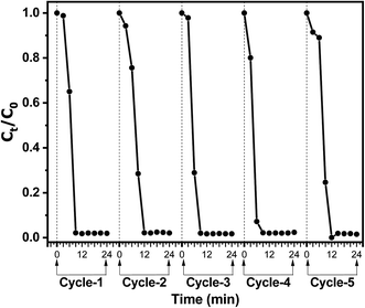
The recyclability of the Au@TiO2 catalytic system was investigated since it is crucial for its practical application. The catalytic performance of the Au@TiO2 system was evaluated for five successive reaction/recovery cycles. Fig. 9 shows the catalytic performance of the Au@TiO2 nanofibers during five successive catalytic cycles. After each cycle, the nanofibers could be easily recovered by filtration from the reaction mixture and further re-dispersed in water to be used in the subsequent catalytic experiment. The results show excellent reproducibility of the catalytic efficiency of the Au@TiO2 nanofibers after each recycling step. Recyclability experiments point out the negligible loss of AuNPs during subsequent reaction/recycling steps and, hence, signify that AuNPs are firmly bound to the fibrous TiO2 porous support.35
Au@TiO2 nanofibers were also tested as a catalyst for catalytic reduction of Congo red dye, which is one of the water pollutants (please see ESI, Fig. S7†). As can be seen, in the presence of excess of sodium borohydride the catalytic reaction follows first order kinetics, with the apparent and normalized rate constants Kapp = 0.019 min−1, Km = 1.95 × 10⁵ L min−1 mol−1, respectively. This further demonstrated the applicability of Au@TiO2 nanofibers as an efficient catalyst for a range of different reactions.
Conclusions
In summary, we report on the fabrication of hollow and porous Au@TiO2 nanofibers, which demonstrate excellent catalytic activity and recyclability during the catalytic reduction of 4-nitrophenol. In the first step, core–shell nanofibers are prepared via coaxial electrospinning. In the second step, the core–shell nanofibers are converted into the hollow nanofibers comprising porous TiO2 shell and immobilized gold nanocatalyst. The appropriate compositional and morphological design of the core–shell nanofibers and optimized subsequent thermal treatment ensure that the AuNPs are trapped in the inner wall of the porous titania shell. This provides a large fraction of the AuNPs to be available for effective contact with the reactants during the catalytic reaction. Hence, the Au@TiO2 exhibit excellent catalytic activity towards the reduction of 4-nitrophenol to 4-aminophenol. Moreover, the Au@TiO2 catalysts is also applicable for catalytic degradation of organic dyes, such as Congo red, which makes it attractive for water purification purposes. Furthermore, the catalyst could be easily recovered and recycled without any noticeable loss in the catalytic activity ensuring the long-term uses of this catalyst system. The present approach could be a promising route for immobilizing various nanosized catalysts in hollow titania support for designing a stable catalyst system where the added photocatalytic activity of titania could further be of a significance.Conflicts of interest
There are no conflicts of interest to declare.Acknowledgements
This research was funded by the Department of Science and Technology, India, grant number INT/FRG/DFG/P-02/2017 and Deutsche Forschungsgemeinschaft (DFG), Germany, grant number HO 5526/2-1. The use of HZDR Ion Beam Center TEM facilities and the support by its staff is gratefully acknowledged. In particular, we acknowledge the funding of TEM Talos by the German Federal Ministry of Education and Research (BMBF), Grant No. 03SF0451 in the framework of HEMCP.References
- C. de Mello Donegá, Chem. Soc. Rev., 2011, 40, 1512–1546 RSC.
- F. Wang, A. Dong and W. E. Buhro, Chem. Rev., 2016, 116, 10888–10933 CrossRef CAS.
- A. Vaneski, J. Schneider, A. S. Susha and A. L. Rogach, J. Photochem. Photobiol., C, 2014, 19, 52–61 CrossRef CAS.
- A. K. Hussein, Renewable Sustainable Energy Rev., 2015, 42, 460–476 CrossRef CAS.
- F. Zaera, Chem. Soc. Rev., 2013, 42, 2746–2762 RSC.
- I. Lee, M. A. Albiter, Q. Zhang, J. Ge, Y. Yin and F. Zaera, Phys. Chem. Chem. Phys., 2011, 13, 2449–2456 RSC.
- Q.-L. Zhu and Q. Xu, Chem, 2016, 1, 220–245 CAS.
- D. Astruc, F. Lu and J. R. Aranzaes, Angew. Chem., Int. Ed., 2005, 44, 7852–7872 CrossRef CAS.
- R. J. White, R. Luque, V. L. Budarin, J. H. Clark and D. J. Macquarrie, Chem. Soc. Rev., 2009, 38, 481–494 RSC.
- A. Sandoval, A. Gómez-Cortés, R. Zanella, G. Díaz and J. M. Saniger, J. Mol. Catal. A: Chem., 2007, 278, 200–208 CrossRef CAS.
- A. Barau, V. Budarin, A. Caragheorgheopol, R. Luque, D. J. Macquarrie, A. Prelle, V. S. Teodorescu and M. Zaharescu, Catal. Lett., 2008, 124, 204–214 CrossRef CAS.
- G. Glaspell, H. M. Hassan, A. Elzatahry, V. Abdalsayed and M. S. El-Shall, Top. Catal., 2008, 47, 22–31 CrossRef CAS.
- R. N. Wrightstone, L. L. Smith, J. Wilson, F. Vella and T. Huisman, Biochim. Biophys. Acta, Protein Struct., 1975, 412, 283–287 CrossRef CAS.
- M. Haruta, Chem. Rec., 2003, 3, 75–87 CrossRef CAS PubMed.
- S. Senkan, M. Kahn, S. Duan, A. Ly and C. Leidholm, Catal. Today, 2006, 117, 291–296 CrossRef CAS.
- D. Tasis, N. Tagmatarchis, A. Bianco and M. Prato, Chem. Rev., 2006, 106, 1105–1136 CrossRef CAS PubMed.
- N. Panziera, P. Pertici, L. Barazzone, A. M. Caporusso, G. Vitulli, P. Salvadori, S. Borsacchi, M. Geppi, C. A. Veracini and G. Martra, J. Catal., 2007, 246, 351–361 CrossRef CAS.
- N. Perkas, Z. Zhong, J. Grinblat and A. Gedanken, Catal. Lett., 2008, 120, 19–24 CrossRef CAS.
- G. Li and Z. Tang, Nanoscale, 2014, 6, 3995–4011 RSC.
- J. C. Park, J. U. Bang, J. Lee, C. H. Ko and H. Song, J. Mater. Chem., 2010, 20, 1239–1246 RSC.
- S. H. Joo, J. Y. Park, C.-K. Tsung, Y. Yamada, P. Yang and G. A. Somorjai, Nat. Mater., 2009, 8, 126 CrossRef CAS.
- T. Zhu, W. L. Ong, L. Zhu and G. W. Ho, Sci. Rep., 2015, 5, 10601 CrossRef CAS.
- A. Celebioglu, K. S. Ranjith, H. Eren, N. Biyikli and T. Uyar, Sci. Rep., 2017, 7, 13401 CrossRef PubMed.
- J. Lee, J. G. Kim and J. Y. Chang, Sci. Rep., 2017, 7, 13568 CrossRef PubMed.
- I. Kim, H. Y. Son, M. Y. Yang and Y. S. Nam, ACS Appl. Mater. Interfaces, 2015, 7, 14415–14422 CrossRef CAS.
- Z. Zhang, C. Shao, P. Zou, P. Zhang, M. Zhang, J. Mu, Z. Guo, X. Li, C. Wang and Y. Liu, Chem. Commun., 2011, 47, 3906–3908 RSC.
- K. R. Brown, D. G. Walter and M. J. Natan, Chem. Mater., 2000, 12, 306–313 CrossRef CAS.
- J. Kimling, M. Maier, B. Okenve, V. Kotaidis, H. Ballot and A. Plech, J. Phys. Chem. B, 2006, 110, 15700–15707 CrossRef CAS.
- H. Dong, E. Fey, A. Gandelman and W. E. Jones, Chem. Mater., 2006, 18, 2008–2011 CrossRef CAS.
- Q.-H. Qin, H. Na, C. Zhang, Q. Yu, X.-Q. Zhang and H.-X. Zhang, J. Nanosci. Nanotechnol., 2015, 15, 3909–3912 CrossRef CAS.
- D. Li and Y. Xia, Nano Lett., 2003, 3, 555–560 CrossRef CAS.
- G. Chang, W. Ullah, Y. Hu, L. Lin, X. Wang and C. Z. Li, Macromol. Rapid Commun., 2018, 1800102 CrossRef.
- B. Li, Y. Hao, B. Zhang, X. Shao and L. Hu, Appl. Catal., A, 2017, 531, 1–12 CrossRef CAS.
- A. Shajkumar, B. Nandan, S. Sanwaria, V. Albrecht, M. Libera, M.-H. Lee, G. Auffermann, M. Stamm and A. Horechyy, J. Colloid Interface Sci., 2017, 491, 246–254 CrossRef CAS PubMed.
- G. Chang, W. Ullah, Y. Hu, L. Lin, X. Wang and C. Z. Li, Macromol. Rapid Commun., 2018, 39, e1800102 CrossRef PubMed.
- S. Sanwaria, S. Singh, A. Horechyy, P. Formanek, M. Stamm, R. Srivastava and B. Nandan, RSC Adv., 2015, 5, 89861–89868 RSC.
- S. Sanwaria, S. Singh, A. Horechyy, P. Formanek, M. Stamm, R. Srivastava and B. Nandan, Nano-Struct. Nano-Objects, 2016, 6, 14–22 CrossRef CAS.
- L. Chu, Z. Qin and J. Yang, Sci. Rep., 2015, 5, 12143 CrossRef CAS.
- S. Dai, Y. Wu, T. Sakai, Z. Du, H. Sakai and M. Abe, Nanoscale Res. Lett., 2010, 5, 1829 CrossRef CAS.
- B. Li, Y. Hao, X. Shao, H. Tang, T. Wang, J. Zhu and S. Yan, J. Catal., 2015, 329, 368–378 CrossRef CAS.
- A. Patterson, Phys. Rev., 1939, 56, 978 CrossRef CAS.
- R. Pandian, G. Natarajan, N. G. K. Dhaipule, A. K. Prasad, M. Kamruddin and A. Tyagi, Thin Solid Films, 2016, 616, 466–476 CrossRef CAS.
- S. Pavasupree, Y. Suzuki, S. Yoshikawa and R. Kawahata, J. Solid State Chem., 2005, 178, 3110–3116 CrossRef CAS.
- J. Yu, G. Wang, B. Cheng and M. Zhou, Appl. Catal., B, 2007, 69, 171–180 CrossRef CAS.
- B. Cheng, Y. Le and J. Yu, J. Hazard. Mater., 2010, 177, 971–977 CrossRef CAS PubMed.
- X. Fang, H. Ma, S. Xiao, M. Shen, R. Guo, X. Cao and X. Shi, J. Mater. Chem., 2011, 21, 4493–4501 RSC.
- D. Fattakhova-Rohlfing, A. Zaleska and T. Bein, Chem. Rev., 2014, 114, 9487–9558 CrossRef CAS PubMed.
- X. Zhang, S. Xu and G. Han, Mater. Lett., 2009, 63, 1761–1763 CrossRef CAS.
- S.-H. Wu, C.-T. Tseng, Y.-S. Lin, C.-H. Lin, Y. Hung and C.-Y. Mou, J. Mater. Chem., 2011, 21, 789–794 RSC.
- F. Shaik, W. Zhang, W. Niu and X. Lu, Chem. Phys. Lett., 2014, 613, 95–99 CrossRef CAS.
- S. Panigrahi, S. Basu, S. Praharaj, S. Pande, S. Jana, A. Pal, S. K. Ghosh and T. Pal, J. Phys. Chem. C, 2007, 111, 4596–4605 CrossRef CAS.
- H. Yazid, R. Adnan and M. A. Farrukh, Indian J. Chem., Sect. A: Inorg., Bio-inorg., Phys., Theor. Anal. Chem., 2013, 52, 184–191 Search PubMed.
- P. Wongwisate, S. Chavadej, E. Gulari, T. Sreethawong and P. Rangsunvigit, Desalination, 2011, 272, 154–163 CrossRef CAS.
- M. Hidalgo, J. Murcia, J. Navío and G. Colón, Appl. Catal., A, 2011, 397, 112–120 CrossRef CAS.
- A. Ayati, A. Ahmadpour, F. F. Bamoharram, B. Tanhaei, M. Mänttäri and M. Sillanpää, Chemosphere, 2014, 107, 163–174 CrossRef CAS.
- M. Chen and D. W. Goodman, Acc. Chem. Res., 2006, 39, 739–746 CrossRef CAS.
- M. Chen and D. Goodman, Catal. Today, 2006, 111, 22–33 CrossRef CAS.
- L. Molina and B. Hammer, Phys. Rev. Lett., 2003, 90, 206102 CrossRef CAS PubMed.
- N. Lopez, T. Janssens, B. Clausen, Y. Xu, M. Mavrikakis, T. Bligaard and J. K. Nørskov, J. Catal., 2004, 223, 232–235 CrossRef CAS.
- S. Chakraborty, S. M. Ansar, J. G. Stroud and C. L. Kitchens, J. Phys. Chem. C, 2018, 122, 7749–7758 CrossRef CAS.
- G. Yue, S. Li, D. Li, J. Liu, Y. Wang, Y. Zhao, N. Wang, Z. Cui and Y. Zhao, Langmuir, 2019, 35, 4843–4848 CrossRef CAS PubMed.
- Y. Deng, Y. Cai, Z. Sun, J. Liu, C. Liu, J. Wei, W. Li, C. Liu, Y. Wang and D. Zhao, J. Am. Chem. Soc., 2010, 132, 8466–8473 CrossRef CAS PubMed.
- Y. Hao, X. Shao, B. Li, L. Hu and T. Wang, Mater. Sci. Semicond. Process., 2015, 40, 621–630 CrossRef CAS.
- X. Ning, F. Wei, H. Fu, X. Qu, Z. Xu and S. Zheng, Appl. Surf. Sci., 2018, 445, 535–541 CrossRef CAS.
Footnotes |
| † Electronic supplementary information (ESI) available. See DOI: 10.1039/c9ra10487a |
| ‡ Present Address: Leibniz-Institut für Polymerforschung Dresden e.V., Hohe Strasse 6, Dresden 01069, Germany. |
| This journal is © The Royal Society of Chemistry 2020 |

