 Open Access Article
Development of high-performance mixed matrix reverse osmosis membranes by incorporating aminosilane-modified hydrotalcite
Xinxia Tian *,
Zhen Cao,
Jian Wang,
Jiangrong Chen and
Yangyang Wei
The Institute of Seawater Desalination and Multipurpose Utilization, MNR (Tianjin), Tianjin, 300192, China. E-mail: tianxinxia05@163.com; Tel: +86-2287898130
First published on 4th February 2020
Abstract
Thin film nanocomposite (TFN) reverse osmosis (RO) membranes were prepared by dispersing 3-aminopropyltriethoxysilane (APTES) modified hydrotalcite (HT), designated as A-HT, in aqueous solution and incorporating the nanoparticles in polyamide layers during the interfacial polymerization process. Results of Fourier transform infrared spectroscopy and zeta potential characterization showed the successful modification of nanoparticles by APTES. In addition, Fourier transform infrared spectroscopy suggested that amidation would take place between the aminosilane on APTES and trimesoyl chloride in organic solution, providing firm covalent interaction between the nanoparticles and polyamide matrix. Dynamic light scattering and transmission electron microscopy indicated that aminosilane modification improved dispersibility of the nanoparticles in aqueous solution and obtained membranes, which suppressed the aggregation. Both the covalent interaction and aggregation suppression were beneficial to compatibility between nanoparticles and the polyamide matrix. TFN RO membranes incorporated with A-HT demonstrated excellent performance. Compared with the pristine RO membrane, the water flux of A-HT-0.050 prepared with an optimum A-HT concentration of 0.050 wt% was enhanced by 18.6% without sacrificing the salt rejection. Moreover, the selectivity of A-HT-0.050 was superior to that of HT-0.050 prepared with HT of 0.050 wt%, which proved aminosilane modification of hydrotalcite was beneficial to high membrane performance especially to selectivity.
1. Introduction
Global water scarcity is an important issue of concern, and it becomes serious with population growth, economic development and climate change. Capturing water from non-traditional sources is of prime importance to solve the problem. Reverse osmosis (RO) technology for desalination of seawater and brackish water has attracted wide attention due to its higher efficiency and lower expense compared with the thermal based distillation method.1The thin film composite (TFC) membrane, consisting of an ultrathin polyamide (PA) skin layer and a porous substrate, has been the mainstream product for the reverse osmosis process. The membranes are prepared via interfacial polymerization of amine in the aqueous phase and acyl chloride in the organic phase on the surface of porous substrates, which allow regulation of the skin layer and substrate individually to optimize performance. However, it has been proposed that the TFC membrane exhibits a permeability–selectivity trade-off.2 Thin film nanocomposite (TFN) membranes have specific structures by integrating PA layers with nano-materials for the development of performance. The studies showed that the incorporation of nano-materials into the PA layers of TFC membranes could improve physicochemical properties such as anti-fouling ability, chlorine resistance and their permselectivity.3,4 To date, a variety of nano-materials have been incorporated into PA layers as nanofillers, such as zeolite,5,6 carbon materials (e.g., nanotubes and graphene oxide),7,8 oxides,9,10 metal nanoparticles11 and metal organic frameworks,12,13 etc. In our previous work, the water flux was increased by 19.1% though the incorporation of hydrotalcite (HT) in a polyamide skin layer.14
Most TFN RO membranes are fabricated by dispersing nanoparticles in aqueous or organic solutions and then incorporating them into skin layers during interfacial polymerization. This approach for performance improvement seems more easy and practicable to complicated conventional methods such as regulations of polymeric monomers, modification of membrane surface and invasive post-treatments of obtained membranes. In spite of these attractive advantages, the high surface energy of nano-materials would cause problems during membrane fabrication and application process. The particularly strong interaction within nanoparticles hinders the dispersion and limits the additive amount of nanoparticles in reactive solutions, which is not conducive to the regulations of membrane performance.15 The weak interaction between nanoparticles and PA matrix causes non-selective defects in skin layers, leading to damage of membrane performance. In addition, nanoparticles tend to escape from membranes due to the weak interaction and cause environmental pollution.16
One of the useful methods to suppress both aggregation and incompatibility problems is to alter physicochemical properties of nanoparticles. Introducing functional groups on nanoparticle surface has been suggested as an effective strategy. This objective could be achieved by several methods, such as chemical treatments, grafting of synthetic polymers, ligand exchange techniques and adsorption of polymeric dispersants.16,17 Among these approaches, chemical treatment is the most used in the field of TFN membrane fabrication process. Through selecting particular chain segment, the dispersion of nanoparticles could be improved through the strengthened interaction between functional groups on nanoparticle surface and reactive solution. This would enhance the dispersibility and reduce aggregation of nanoparticles in reactive solution.4 The functional groups promise enhanced interactions between nanoparticles and polymer matrix which improve the compatibility of nanoparticles in polymer.18 Meanwhile, appropriate functional groups on nanoparticle surface could form covalently bond with polymer matrix. This kind of interaction provides strong interaction between nanoparticles and polymer matrix, ensuring the high stability.19
In the previous study, HT demonstrated the advantages in improving the flux of RO membranes due to the structure.14 To take full use of HT in improving RO membrane performance, we proposed the modification of HT nanoparticles to improve both dispersibility and compatibility. Silane coupling agents have been recently applied as coupling agents to modify nanoparticle surfaces and promote adhesion in the fabrication of nanocomposite membranes.20–22 Siloxy reacts with inorganic nanoparticles, and organic functional groups possess compatibility or reactivity with organics. Hence, the bifunctional molecules act as intermediate materials to link two dissimilar materials. In order to improve the interfacial compatibility between HT and polyamide in TFN RO membranes, we proposed the idea to build covalent bonds between the two materials.
In this work, aminosilane-modified HT (A-HT) were used as the nano-filler and dispersed in aqueous solution during interfacial polymerization process to fabricate TFN RO membranes. The surface modification weakens the interaction among nanoparticles, suppressing the agglomeration in reactive solution and obtained membranes, which is beneficial to the homogeneity of membrane structure. The amino groups anchoring on A-HT would react with acyl chloride groups of trimesoyl chloride (TMC) which is the monomer in organic phase during interfacial polymerization. The covalent bonds built by chemical reaction enhance the compatibility of nanoparticles and PA matrix from the molecular structure level. Both of the dispersibility and compatibility enhancements ensure the improvement of TFN RO membranes.
2. Experiment
2.1 Materials
m-Phenylenediamine (MPD, AR) and 10-camphor sulfonic acid (CSA, AR) were purchased from Aladdin Co., Ltd. Triethylamine (TEA, AR) was purchased from Tianjin Fengchuan Chemical Reagent Co., Ltd. Sodium dodecyl sulfate (SDS, ≥99.0%) was purchased from Sigma-Aldrich. Trimesoyl chloride (TMC, 98%) was purchased from Tianjin Heowns Biochemical Technology Co. Ltd. Solvent n-hexane (AR) was purchased from Tianjin Kemiou Chemical Reagent Co., Ltd. Magnesium nitrate hexahydrate (Mg(NO3)2·6H2O, AR), aluminum nitrate nonahydrate (Al(NO3)3·9H2O, AR), sodium hydroxide (NaOH, AR), sodium carbonate (Na2CO3, AR) and 3-aminopropyltriethoxysilane (APTES 99%) were purchased from Sigma-Aldrich. Deionized water was produced by a home-made reverse osmosis system. Polysulfone (PSf) ultrafiltration membranes were home-made by immersion precipitation phase inversion as porous substrates. Deionized water was produced by a reverse osmosis system.2.2 Synthesis and surface modification of hydrotalcite
The HT was prepared via hydrothermal method as mentioned in our previous study.14 The synthesis was carried out in a three-neck flask with a reflux condenser. In a typical procedure, 0.06 mol Mg(NO3)2·6H2O and 0.02 mol Al(NO3)3·9H2O were dissolved in 100 mL water solution containing 20 vol% ethanol. Then, the mixed basic solution of 2 M NaOH and 1 M Na2CO3 was added dropwise into the flask with stirring until the pH value reached to 10. The slurry obtained was stirred for an additional 30 min, and then was put into a stainless steel reactor and hydrothermally treated at 393.15 K for 24 hours. The resulting white solid product was centrifuged, washed with mixed solution of deionized water and anhydrous ethanol several times, air-dried at room temperature, and finally HT was obtained.The surface modification of HT was carried out under moderate reaction conditions.23 Firstly, 6 g coupling agent APTES and 3 g synthesized HT were mixed in 150 mL n-heptane. Then, the reaction mixture was violently stirred for 24 h, and the non-reacted silane coupling agent was separated out by several n-heptane washing via centrifugation. Finally, the modified HT was dried under vacuum for 5 hours at room temperature, and then heated at 200 °C under vacuum for 3 hours to thoroughly remove residual solvent. The APTES-modified HT was designated as A-HT.
2.3 Preparation of RO membranes
RO membranes were prepared via interfacial polymerization method. Solution containing MPD (2.0 wt%), TEA (1.1 wt%), CSA (2.6 wt%) and SDS (0.1 wt%) was used as aqueous phase. Solution containing 0.1 wt% TMC in n-hexane was used as organic phase. Firstly, the aqueous solution was contacted with the top surface of the substrates for 1 min, and then the excess solution was removed by pressing the surface with a soft rubber roller. Afterwards, organic solution was coated thereon and contacted with the top surface of the substrates for 1 min for the reaction of TMC and MPD. Finally, the excess organic solution was removed and the resulting membrane was heated in an air-circulated dryer at 80 °C for 5 min. In a similar procedure, the nanoparticle-incorporated membranes were prepared by dispersing the nanoparticles into the aqueous solution. The TFN RO membranes prepared with aqueous solution containing A-HT were designated as A-HT-n, where n represented the nanoparticle percentage content. The TFN RO membrane prepared with aqueous solution containing 0.050 wt% HT was designated as HT-0.050.2.4 Characterization of nanoparticles and RO membranes
The chemical structure of nanoparticles and RO membranes was characterized by attenuated total reflection Fourier transform infrared spectroscopy (ATR-FTIR, iS50, Nicolet of USA). The morphology of nanoparticles and RO membranes was observed by scanning electron microscope (SEM, Nova Nano450, FEI of USA). The diameter of nanoparticles and zeta potentials of nanoparticles were estimated via dynamic light scattering (DLS, NanoBrook Omni, Brookhaven Instrument of USA). The existence and dispersion state of nanoparticles in PA layer of TFN RO membranes were verified by transmission electron microscope (TEM, H7650, Hitachi of Japan). The surface roughness of RO membranes was characterized by atomic force microscopy (AFM, SmartSPM-1000, AIST-NT of USA). The surface hydrophilicity of RO membranes was evaluated by contact angle goniometer (JC2000D2, Zhongchen of China). The desalination performance of the RO membranes was evaluated in terms of water flux and salt rejection by a lab-scale cross-flow water permeation apparatus. Membranes were initially compacted at 1.55 MPa transmembrane pressure (TMP) for 0.5 h to reach a steady state. Then, the water flux was measured at 1.55 MPa TMP and 25 °C. The water flux J was calculated by the following equation:where A (m2) is the effective membrane area, V (L) is the volume of permeated water and Δt (h) is the permeation time.
Salt rejection R was calculated using the following equation:
3. Results and discussion
3.1 Characterization of nanoparticles and RO membranes
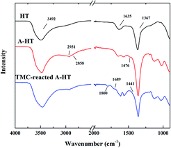
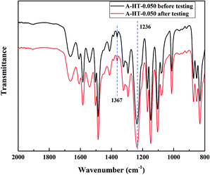
ATR-FTIR was used to confirm the successful surface modification of nanoparticles and the amidation between A-HT and TMC. The ATR-FTIR spectra of original HT, A-HT and TMC-reacted A-HT are shown in Fig. 1. The intense peaks at 3492 cm−1 are assigned to the vibrational absorption of O–H, which can be attributed to the interlayer water molecules and the hydroxyl groups in the brucite-like layers. The weak peak at 1635 cm−1 is assigned to the vibrational absorption from the interlayer water. The strong peak at 1367 cm−1 is assigned to the asymmetric stretching of the carbonate. The spectra suggest the successful synthesis of HT.24 New peaks at 2931, 2858 and 1476 cm−1 emerged in the A-HT. The peaks at 2931 and 2858 cm−1 can be ascribed to C–H asymmetric stretching and C–H symmetric stretching absorption, respectively.25 The peak at 1464 cm−1 can be attributed to the N–H stretching absorption of the aminopropyl groups.26 The new peaks confirmed the presence of APTES on A-HT, which indicated the successful modification of nanoparticles. For the TMC-reacted A-HT, the new peaks at 1800 cm−1 and 1441 cm−1 could be assigned to the C![[double bond, length as m-dash]](https://www.rsc.org/images/entities/char_e001.gif) O stretching absorption and O–H deformation of carboxylic acid group, which came from the hydrolysis of the unreacted acyl chloride unit.27 The peak at 1689 cm−1 can be ascribed to C
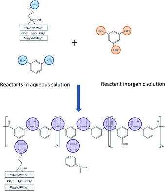
O stretching absorption and O–H deformation of carboxylic acid group, which came from the hydrolysis of the unreacted acyl chloride unit.27 The peak at 1689 cm−1 can be ascribed to C![[double bond, length as m-dash]](https://www.rsc.org/images/entities/char_e001.gif) O stretching of amide derived from the reaction of A-HT and TMC, which indicates that amidation has proceeded between amine-terminated A-HT and TMC.28 Hence, the reaction shown in Fig. 2 supposed to occur during the whole membrane fabrication.
O stretching of amide derived from the reaction of A-HT and TMC, which indicates that amidation has proceeded between amine-terminated A-HT and TMC.28 Hence, the reaction shown in Fig. 2 supposed to occur during the whole membrane fabrication.
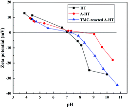
As the surface functional groups could influence surface charge character of nanoparticle, zeta potential and isoelectric point measurement is an approach to investigate the grafting reaction of HT and the amidation between A-HT and TMC.29 Fig. 2 shows the zeta potentials of HT, A-HT and TMC-reacted A-HT over a pH 3–10 range at 25 °C. As can be seen from Fig. 3, APTES modification results in more positive charges on particle surface, which can be ascribed to the introduction of amine groups as they would be protonated in water.30 After reaction with TMC, the nanoparticles become relatively negative due to the consumption of the amine groups and instruction of carboxylic acid groups which come from the dissociation of acyl chloride groups.28,31 The variation of zeta potentials in Fig. 3 indicates the successful modification of HT by APTES and reaction of A-HT with TMC.
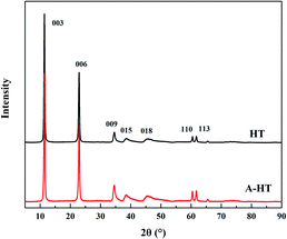
XRD was used to observe the crystal structure of the nanoparticles and investigate the influence of APTES modification on HT. The XRD patterns of original HT and A-HT are shown in Fig. 4. The characteristic peaks of HT at 11.4°, 22.9°, 34.7°, 38.6°, 45.9°, 60.5° and 61.8° corresponding to Miller indices (003), (006), (009), (015), (018), (110) and (113) can be observed in both original and APTES modified HT.32 The XRD patterns shown in Fig. 3 not only confirm the success synthesis of HT, but also demonstrate that A-HT exhibites the same crystalline structure as original HT. The result implies that APTES-modification does not alter crystalline structure of nanoparticles, which is consistent with the existing researches.33 As the crystalline structure determines the channel size for water, the A-HT possesses the same high water transport channels as HT, which would ensure the high permeability of the TFN RO membranes.14
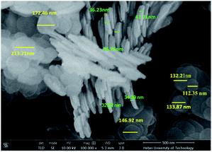
SEM was used to observe the morphology of A-HT, as shown in Fig. 5. The A-HT exhibit thin nanosheet morphology, which is typical for hydrotalcite nanoparticles.32 The nanoparticles with completely-exposed profile and front faces were investigated to obtain the thickness and diameter of the A-HT. It can be seen from Fig. 4 that the thickness and the diameter of the A-HT range from 32 to 42 nm and 110 to 220 nm, respectively. The size of A-HT is roughly similar with the original HT, which implies that the APTES-modification will not alter the morphology feature of the nanoparticles.14
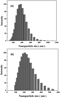
DLS technique was used to study sizes of nanoparticles in aqueous solution. As shown in Fig. 6(a), original HT nanoparticles tend to form nano-clusters with size around 400 nm. The size measured by DLS is obviously larger than that shown in SEM images, which suggests that HT tend to aggregate when dispersed in aqueous solution. After modification, the size of nanoparticles reduces to around 200 nm. The results indicate APTES modification could remarkably prevent aggregation of the particles and increase the affinity of the surface for the solvent.17
3.2 Characteristics of the RO membranes
| RO membrane | Ra (nm) | Rm (nm) |
|---|---|---|
| A-HT-0 | 58.4 | 74.8 |
| A-HT-0.010 | 56.3 | 71.3 |
| A-HT-0.025 | 51.3 | 64.5 |
| A-HT-0.050 | 50.3 | 62.9 |
| A-HT-0.075 | 49.8 | 61.9 |
| A-HT-0.100 | 46.4 | 57.8 |
| A-HT-0.125 | 45.0 | 55.9 |
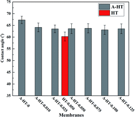
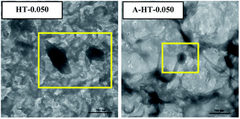
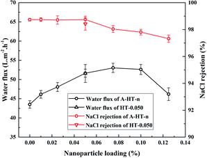
In order to investigate the influence of aminosilane modification of nanoparticles on TFN RO membranes, performance of HT-0.050 was also tested. The water flux of HT-0.05 is 51.5 ± 2.3 L m−2 h−1, which is almost the same as that of A-HT-0.050 (51.6 ± 1.1 L m−2 h−1). Conversely, the aminosilane modification of nanoparticles increased the NaCl rejection from 98.4 ± 0.5% of HT-0.05 to 98.7 ± 0.2% of A-HT-0.050. Although the rejection enhancement is not that much, it would largely influence the economical performance of desalination in practice.2 Moreover, the smaller standard deviation of A-HT-0.050 indicates that the uniformity of membranes enhanced. The variation of selectivity could be ascribed to the improvement of compatibility between nanoparticles and polyamide matrix. Aminosilane modification suppresses the aggregation and the nanoparticle size decreases, as shown in Fig. 6 and 9. Moreover, the reaction between amino groups of APTES and TMC (see Fig. 1) links nanoparticles and polyamide matrix together. Dispersion improvement and reaction suppress the formation of voids without separation property between nanoparticles and the matrix. Hence, the selectivity of the membrane is enhanced.
The performance of A-HT incorporated RO membranes obtained in this work and typical TFN RO membranes reported by references have been summarized in Table 2. Many TFN RO membranes show high water flux and salt rejection. The membranes incorporated with 0.050% wt% A-HT in our work is superior in either water flux or salt rejection compared with membranes in Table 2 except for that incorporated with NaY zeolite. Considering both of water flux and salt rejection, the membranes obtained in this work are competitive among the state-of-the-art TFN RO membranes, indicating that incorporating A-HT in polyamide layer is an effective approach to fabricate RO membranes with excellent permeability and selectivity.
| Nanoparticles in RO membranes | NaCl (ppm) | Pressure (MPa) | Water flux (L m−2 h−1) | Rejection (%) | References |
|---|---|---|---|---|---|
| NaA zeolite | 2000 | 1.24 | — | 93.9 | 5 |
| NaY zeolite | 2000 | 1.55 | 74.2 | 98.8 | 6 |
| Silicate-1 zeolite | 2000 | 1.6 | 66.6 | 96.4 | 45 |
| ZIF-8 | 2000 | 1.5 | 34.5 | 99.4 | 46 |
| Zwitterion functionalized CNT | 2000 | 2.41 | 34.7 | 98.5 | 47 |
| PAAm grafted MWCNTs | 2000 | 1.55 | 48.4 | 98.9 | 4 |
| PMSA-g-GO | 1000 | 1.2 | 17.5 | 94.8 | 48 |
| GO | 2000 | 1.55 | 16.6 | 99.4 | 49 |
| SiO2 | 2000 | 1.5 | 123 | 98.0 | 9 |
| PEI modified SiO2 | 2000 | 1.5 | 17.4 | 96.0 | 18 |
| LDH | 2000 | 1.6 | 41.7 | 99.3 | 40 |
| APTES modified HT | 2000 | 1.55 | 51.5 | 98.7 | This work |
4. Conclusions
In this work, APTES modified HT, denoted as A-HT, was used to fabricate TFN RO membranes with satisfactory permeability and selectivity. Both FTIR and zeta potential characterizations certified the successful modification. By introducing amino-terminated aminosilane to HT surface, nanoparticles exhibited better dispersibility in aqueous solution with smaller particle size, which was beneficial to the homogenously distribution of nanoparticles in obtained membranes. In addition, amino on A-HT reacted with acyl chloride of TMC, which provided firm bonds between nanoparticles and polyamide matrix. Those two features improved the compatibility between nanoparticles and polyamide, suppressing the formation of defects inside skin layer, which guaranteed excellent permselectivity of membranes. When the addition content was 0.050 wt%, water flux of the TFN RO membrane was increased by 18.6% without NaCl rejection loss. Nanoparticles provided high-speed channels for water, and simultaneously, good compatibility between A-HT and polyamide guaranteed rejection. Moreover, the selectivity of A-HT-0.050 was superior to that of HT-0.050, which proved that aminosilane modification of hydrotalcite was beneficial to high membrane performance especially to selectivity. As preparation performance of RO membranes affects the cost of desalination process, incorporation of aminosilane-modified nanoparticles is an effective approach to enhance the economical performance of sea water and brackish water desalination.Conflicts of interest
There are no conflicts to declare.Acknowledgements
This research was supported by the National Key Research and Development Program of China (grant number 2018YFC0408002), the Basic Scientific Research Funds for the State-Level Scientific Research Institute (grant numbers K-JBYWF-2019-T04, K-JBYWF-2018-HZ01).References
- M. A. Shannon, P. W. Bohn, M. Elimelech, J. G. Georgiadis, B. J. Marinas and A. M. Mayes, Nature, 2008, 452, 301–310 CrossRef CAS PubMed.
- J. R. Werber, C. O. Osuji and M. Elimelech, Nat. Rev. Mater., 2016, 1, 16018 CrossRef CAS.
- S.-M. Xue, C.-H. Ji, Z.-L. Xu, Y.-J. Tang, R.-H. Li and S.-M. Xue, J. Membr. Sci., 2018, 545, 185–195 CrossRef CAS.
- M. Zhao, S. Fu, H. Zhang, H. Huang, Y. Wei and Y. Zhang, RSC Adv., 2017, 7, 46969–46979 RSC.
- B.-H. Jeong, E. M. V. Hoek, Y. Yan, A. Subramani, X. Huang, G. Hurwitz, A. K. Ghosh and A. Jawor, J. Membr. Sci., 2007, 294, 1–7 CrossRef CAS.
- H. Dong, L. Zhao, L. Zhang, H. Chen, C. Gao and W. S. W. Ho, J. Membr. Sci., 2015, 476, 373–383 CrossRef CAS.
- R. Bi, Q. Zhang, R. Zhang, Y. Su and Z. Jiang, J. Membr. Sci., 2018, 553, 17–24 CrossRef CAS.
- J. Zheng, M. Li, K. Yu, J. Hu, X. Zhang and L. Wang, J. Membr. Sci., 2017, 524, 344–353 CrossRef CAS.
- H. Shen, S. Wang, H. Xu, Y. Zhou and C. Gao, J. Membr. Sci., 2018, 565, 145–156 CrossRef CAS.
- H. S. Lee, S. J. Im, J. H. Kim, H. J. Kim, J. P. Kim and P. M. Jong, Desalination, 2008, 219, 48–56 CrossRef CAS.
- E.-S. Kim, G. Hwang, M. G. El-Din and Y. Liu, J. Membr. Sci., 2012, 394, 37–48 CrossRef.
- C. V. Goethem, R. Verbeke, M. Pfanmöller, T. Koschine, M. Dickmann, T. Timpel-Lindner, W. Eggerf, S. Balsb and I. F. J. Vankelecom, J. Membr. Sci., 2018, 563, 938–948 CrossRef.
- T. H. Lee, J. Y. Oh, S. P. Hong, J. M. Lee, S. M. Roh, S. H. Kim and H. B. Park, J. Membr. Sci., 2019, 570–571, 23–33 CrossRef CAS.
- X. Tian, J. Wang, H. Zhang, Z. Cao, M. Zhao, Y. Guan and Y. Zhang, RSC Adv., 2018, 8, 12439–12448 RSC.
- C. V. Goethem, V. S. Hermans, R. Bernsteinb and I. F. J. Vankelecoma, J. Mater. Chem. A, 2016, 4, 16368–16376 RSC.
- S. A. Aani, C. J. Wright, M. A. Atiehc and N. Hilal, Desalination, 2017, 401, 1–15 CrossRef.
- S. Kango, S. Kalia, A. Celli, J. Njuguna, Y. Habibi and R. Kumar, Prog. Polym. Sci., 2013, 38, 1232–1261 CrossRef CAS.
- M. Zargar, Y. Hartanto, B. Jin and S. Dai, J. Membr. Sci., 2017, 541, 19–28 CrossRef CAS.
- M. Zargar, Y. Hartanto, B. Jin and S. Dai, J. Membr. Sci., 2017, 521, 53–64 CrossRef CAS.
- S. Li, Z. Chen, Y. Yang, Z. Si, P. Li, P. Qin and T. Tan, Sep. Purif. Technol., 2019, 215, 163–172 CrossRef CAS.
- M. Laghaei, M. Sadeghi, B. Ghalei and M. Shahrooz, J. Membr. Sci., 2016, 513, 20–32 CrossRef CAS.
- S. Yi, B. Qi, Y. Su and Y. Wan, Chem. Eng. J., 2015, 279, 547–554 CrossRef CAS.
- N. Wang, J. Liu, J. Li, J. Gao, S. Ji and R. Li, Microporous Mesoporous Mater., 2015, 201, 35–42 CrossRef CAS.
- F. Millange, R. I. Walton and D. O'Hare, J. Mater. Chem., 2000, 10, 1713–1720 RSC.
- D. K. Bhowmick, S. Linden, A. Devaux and L. D. Cola, Small, 2012, 8, 592–601 CrossRef CAS PubMed , 619.
- A. Z. Siavashani, M. H. Nazarpak, F. Fayyazbakhsh, T. Toliyat, S. J. P. McInnes and M. Solati-Hashjin, J. Mater. Sci., 2016, 51, 10897–10909 CrossRef.
- S. Zhu, S. Zhao, Z. Wang, X. Tian, M. Shi, J. Wang and S. Wang, J. Membr. Sci., 2015, 493, 263–274 CrossRef CAS.
- J. Xu, Z. Wang, L. Yu, J. Wang and S. Wang, J. Membr. Sci., 2013, 435, 80–91 CrossRef CAS.
- H. Kang, D. J. Long and C. L. Haynes, Langmuir, 2019, 35, 7985–7994 CrossRef CAS PubMed.
- J. Xu, Z. Wang, J. Wang and S. Wang, Desalination, 2015, 365, 398–406 CrossRef CAS.
- Y. Wang, Z. Wang and J. Wang, J. Membr. Sci., 2018, 554, 221–231 CrossRef CAS.
- J. Liao, Z. Wang, C. Gao, M. Wang, K. Yan, X. Xie, S. Zhao, J. Wang and S. Wang, J. Mater. Chem. A, 2015, 3, 16746–16761 RSC.
- X. Zhuang, X. Chen, Y. Su, J. Luo, S. Feng, H. Zhou and Y. Wan, J. Membr. Sci., 2016, 499, 386–395 CrossRef CAS.
- R. Dingreville, J. Qu and C. Mohammed, J. Mech. Phys. Solids, 2005, 53, 1827–1854 CrossRef CAS.
- H. Huang, H. Zhang, Y. Wei, M. Zhao and Y. Zhang, Desalin. Water Treat., 20, 106, 21–31 CrossRef.
- Z. Fan, Z. Wang, M. Duan, J. Wang and S. Wang, J. Membr. Sci., 2008, 310, 402–408 CrossRef CAS.
- A. K. Ghosh, B. H. Jeong, X. Huang and E. M. V. Hoek, J. Membr. Sci., 2008, 311, 34–45 CrossRef CAS.
- A. V. Berezkin and A. R. Khokhlov, Mathematical modeling of interfacial polycondensation, J. Polym. Sci., Part B: Polym. Phys., 2006, 44, 2698–2724 CrossRef CAS.
- S. Li, Z. Wang, C. Zhang, M. Wang, F. Yuan, J. Wang and S. Wang, J. Membr. Sci., 2013, 436, 121–131 CrossRef CAS.
- H. Dong, L. Zhao, L. Zhang, H. Chen, C. Gao and W. S. W. Ho, J. Membr. Sci., 2015, 476, 373–383 CrossRef CAS.
- P. Wei, X. Qu, H. Dong, L. Zhang, H. Chen and C. Gao, J. Appl. Polym. Sci., 2013, 128, 3390–3397 CrossRef CAS.
- A. E. Amooghin, M. Omidkhah and A. Kargari, J. Membr. Sci., 2015, 490, 364–379 CrossRef.
- C. L. Li, S. H. Huang, D. J. Liaw, K. R. Lee and J. Y. Lai, Sep. Purif. Technol., 2008, 62, 694–701 CrossRef CAS.
- M. Duan, Z. Wang, J. Xu, J. Wang and S. Wang, Sep. Purif. Technol., 2010, 75, 145–155 CrossRef CAS.
- H. Huang, X. Qu, X. Ji, X. Gao, L. Zhang, H. Chen and L. Hou, J. Mater. Chem. A, 2013, 1, 11343–11349 RSC.
- I. H. Aljundi, Desalination, 2017, 420, 12–20 CrossRef CAS.
- W.-F. Chan, E. Marand and S. M. Martin, J. Membr. Sci., 2016, 509, 125–137 CrossRef CAS.
- H. Mahdavi and A. Rahimi, Desalination, 2018, 433, 94–107 CrossRef CAS.
- H. R. Chae, J. Lee, C. H. Lee, I. C. Kim and P. K. Park, J. Membr. Sci., 2015, 483, 128–135 CrossRef CAS.
- J. Wang, Q. Wang, X. Gao, X. Tian, Y. Wei, Z. Cao, C. Guo, H. Zhang, Z. Ma and Y. Zhang, Front. Environ. Sci. Eng., 2020, 14, 6 CrossRef CAS.
| This journal is © The Royal Society of Chemistry 2020 |


