 Open Access Article
Surface double coating of a LiNiaCobAl1−a−bO2 (a > 0.85) cathode with TiOx and Li2CO3 to apply a water-based hybrid polymer binder to Li-ion batteries†
Tatsuya Watanabea,
Kouji Hiraia,
Fuma Andoa,
Shoudai Kurosumib,
Shinsaku Ugawab,
Hojin Leeb,
Yuta Iriic,
Fumihiko Makic,
Takao Gunji a,
Jianfei Wu
 d,
Takao Ohsakae and
Futoshi Matsumoto
 *a
*a
aDepartment of Materials and Life Chemistry, Kanagawa University, 3-27-1, Rokkakubashi, Kanagawa-ku, Yokohama, Kanagawa 221-8686, Japan. E-mail: fmatsumoto@kanagawa-u.ac.jp
bJSR Corporation, 100 Kawajiri-cho, Yokkaichi, Mie 510-8552, Japan
cNihon Kagaku Sangyo Co., Ltd., 1-28-13 Nakane, Soka, Saitama 340-0005, Japan
dQingdao Industrial Energy Storage Research Institute, Qingdao Institute of Bioenergy and Bioprocess Technology, Chinese Academy of Sciences, No. 189 Songling Road, 266101 Qingdao, China
eResearch Institute for Engineering, Kanagawa University, 3-27-1, Rokkakubashi, Kanagawa-ku, Yokohama, Kanagawa 221-8686, Japan
First published on 3rd April 2020
Abstract
Recently a water-based polymer binder has been getting much attention because it simplifies the production process of lithium ion batteries (LIBs) and reduce their cost. The surface of LiNiaCobAl1−a−bO2 (a > 0.85, NCA) cathode with a high voltage and high capacity was coated doubly with water-insoluble titanium oxide (TiOx) and Li2CO3 layers to protect the NCA surface from the damage caused by contacting with water during its production process. The TiOx layer was at first coated on the NCA particle surface with a tumbling fluidized-bed granulating/coating machine for producing TiOx-coated NCA. However, the TiOx layer could not coat the NCA surface completely. In the next place, the coating of the TiOx-uncoated NCA surface with Li2CO3 layer was conducted by bubbling CO2 gas in the TiOx-coated NCA aqueous slurry on the grounds that Li2CO3 is formed through the reaction between CO32− ions and residual LiOH on the TiOx-uncoated NCA surface, resulting in the doubly coated NCA particles (TiOx/Li2CO3-coated NCA particles). The Li2CO3 coating is considered to take place on the TiOx layer as well as the TiOx-uncoated NCA surface. The results demonstrate that the double coating of the NCA surface with TiOx and Li2CO3 allows for a high water-resistance of the NCA surface and consequently the TiOx/Li2CO3-coated NCA particle cathode prepared with a water-based binder possesses the same charge/discharge performance as that obtained with a “water-uncontacted” NCA particle cathode prepared using the conventional organic solvent-based polyvinylidene difluoride binder.
1. Introduction
In recent years, water-soluble and aqueous polymer binders, i.e., water-based polymer binders, have become of great interest as alternatives to the poly(vinylidene difluoride) (PVdF) binder dissolved in N-methyl-2-pyrrolidone (NMP) for the cathodes of lithium ion batteries (LIBs) from the viewpoints of environmentally friendly electrode fabrication processes and reducing the cost of LIBs.1–13 However, cathode materials such as LiNi0.5Mn1.5O4,11 LiNiaCobAl1−a−bO2 (NCA)12 and Li-rich solid-solution layered cathodes,13 which are promising candidates as next generation positive-electrode active materials with high energy density for LIBs, are not stable in water-based slurry solutions because they contain a small amount of alkaline species such as LiOH as aresidue in their production process14 and when they are dispersed in a water-based coating slurry, their surfaces are dissolved and its pH is increased, resulting in the corrosion of the Al foil current collectors and the falling off of active cathode materials from the current collector surfaces.12 To prevent such a damage of cathode materials some ways have been proposed including the use of buffer agents to inhibit the increase in pH in the water-based slurry15 and a stainless steel foil current collector16 and the surface coating of cathode materials by carbon,11 metal oxides12 and Li2CO3.17,18In a series of our studies on surface coating of cathode materials,11,12,19 we have found that Li+ ions can relatively smoothly pass through the thin layers of carbon, Al2O3 and TiOx on NCA particles and the thin layer coating of NCA particles by TiOx significantly suppresses, though not completely, the degradation in charge/discharge cyclability which is caused by contacting their surfaces with water, i.e., TiOx-coated NCA cathode particles possess a water-resistant property when kept in the water-based slurry. The TiOx coating process in this case is a so-called batch process and thus it is not suitable for the mass production of TiOx-coated cathode materials.
Recently, Yanagida et al.17,18 have developed a simple continuous method to decrease the pH value of the NCA cathode aqueous slurry with CO2 gas treatment using a cavitation effect in which the NCA particle surfaces are covered with the Li2CO3 layer formed by reacting the LiOH dissolved in the cathode slurry with the CO2 gas introduced into it and the Li2CO3 layer prevents the electrolyte decomposition and reaction of the NCA particle surfaces with the electrolyte, resulting in improvement of the cyclability, coulombic efficiency and high-capacity retention rate of the Li2CO3-coated NCA cathode. They have claimed that their CO2 gas treatment can be a continuous process for mass production. The CO2 gas treatment of cathode particles is thus effective to protect their surface against water17,20,21 and could be scaled up to the mass production of Li2CO3-coated cathode materials. However, it should be also noted that Li2CO3 is electrochemically insulating which may block the electronic transport of the Li2CO3-coated cathode materials and consequently leads to the capacity degradation due to the accumulation of Li2CO3 in the interface between the cathode particle surface and electrolyte.22,23 Thus, a suitable Li2CO3 layer coating is desirable. In addition, as mentioned later based on our examination on the water-resistance of NCA cathode particles coated with Li2CO3 layer by the CO2 gas treatment, CO2 gas-treated NCA samples could not exhibit full charge/discharge capacities because they suffered from a small surface damage (surface dissolution) by contacting with water owing to the uncomplete coating of the whole surface of NCA particles by the Li2CO3 layer, i.e., the NCA surface coating only by the Li2CO3 layer was not adequate for the present purpose.
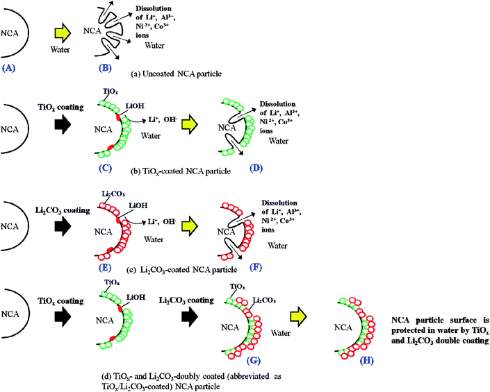
In order to protect the NCA surfaces from the damage caused by contacting them with water during their production process using water-based binder, in this study, we aimed at doubly coating the NCA particle surfaces with TiOx and Li2CO3 layers, by using a surface coating procedure which may be applicable for the mass production of surface-coated NCA particles for commercially available LIBs, i.e., by at first coating the NCA surface with TiOx layer using a tumbling fluidized-bed granulating/coating machine, which is used to form coating layers in a wide range of industries including pharmaceuticals, foods and battery materials,24 (producing TiOx-coated NCA particles which are not coated completely by the TiOx layer) and then by coating the TiOx-coated as well as TiOx-uncoated NCA surfaces with Li2CO3 layer by bubbling CO2 gas in the TiOx-coated NCA aqueous slurry (finally producing the doubly coated NCA particles, abbreviated as TiOx/Li2CO3-coated NCA particles), as schematically shown in Fig. 1. We found that the TiOx layer does not coat the NCA surface completely and thus there are some TiOx-uncoated parts, but such TiOx-uncoated surfaces are covered with the subsequent Li2CO3 layer coating and consequently the TiOx/Li2CO3-coated NCA particles have a high water-resistance and that the charge/discharge performance of the TiOx/Li2CO3-coated NCA cathode prepared with a water-based binder is significantly superior to those of the TiOx- or Li2CO3-coated cathodes and almost comparable to that obtained with “water-uncontacted” NCA cathode prepared using the conventional organic solvent (NMP)-based PVdF binder. The samples of un-, TiOx-, Li2CO3- and TiOx/Li2CO3-coated NCA particles that are prepared and treated with water after the preparation will hereinafter be denoted using the upper-case alphabetic characters of A–H, as shown Fig. 1.
2. Experimental
2.1 Preparation of TiOx-coated NCA cathode material and NCA cathode electrodes
NCA particles (NC-02, LiNiaCobAl1−a−bO2 (a > 0.85)) were provided by Nihon Kagaku Sangyo Co., Ltd., Japan and used without any purification. In order to coat the surface of NCA with TiOx layer, a tumbling fluidized-bed granulating/coating machine (MP-micro, Powrex Corporation, Japan) was used (Fig. 2). The temperature in the chamber was set at 80 °C. During the operation, NCA particles were floated in the chamber with air and a TiOx-precursor solution in which titanium tetraisopropoxide (TTIP, 95%, Wako Pure Chemicals Co. Ltd. (Wako), Japan) was dissolved in 2-propanol (99.7%, Wako) was sprayed in the chamber. After a very small amount of droplets of the solution was deposited on the surface of NCA particles, the solvent of the droplets was evaporated and then the TiOx precursor was coated on the NCA surfaces. The optimum spray conditions were examined by changing the concentration of TTIP, the spray speed and the total amount of the solution sprayed. After coating the TiOx precursor, the NCA particles were sintered at 450 °C for 2 h under argon atmosphere to form the TiOx layer on their surface, resulting in TiOx-coated NCA particles. TiOx-coated NCA samples C-1–C-5 were prepared at different spray conditions as summarized in Table 1.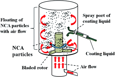 | ||
| Fig. 2 Schematic drawing of a tumbling fluidized-bed granulating/coating machine to prepare TiOx-coated NCA particles. | ||
| Sample number | C-1 | C-2 | C-3 | C-4 | C-5 |
|---|---|---|---|---|---|
| Concentration of TTIP (wt%) | 5.3 | 36 | 36 | 36 | 36 |
| Spray speed (g min−1) | 20 | 20 | 2.0 | 2.0 | 20 |
| Total amount of the solution sprayed (g) | 0.50 | 0.50 | 0.50 | 0.25 | 0.25 |
TiOx-coated NCA cathode was prepared as follows: 910 mg of accurately weighed TiOx-coated NCA particles and 50 mg of acetylene black (AB, Denka Black, Denki Kagaku Gogyo, Japan) were mixed on a mortar with a pestle, and 10 mg of carboxymethyl cellulose (CMC, Polyscience Inc, cat.#6139) and 30 mg of water-based hybrid polymer binder (TRD202A, JSR, Japan) were mixed in Milli-Pore water (1.1 g, >18 MΩ). Then, the mixture of TiOx-coated NCA particles and AB was added to the CMC/TRD202A-mixed aqueous solution. The resulting mixed solution containing TiOx-coated NCA particles, TRD202A, AB and CMC was further mixed with a planetary mixing equipment (Mazerustar, KK-250S, KURABO, Japan) until it became a homogenous slurry. The weight% of TiOx-coated NCA powder![[thin space (1/6-em)]](https://www.rsc.org/images/entities/char_2009.gif) :
:![[thin space (1/6-em)]](https://www.rsc.org/images/entities/char_2009.gif) TRD202A
TRD202A![[thin space (1/6-em)]](https://www.rsc.org/images/entities/char_2009.gif) :
:![[thin space (1/6-em)]](https://www.rsc.org/images/entities/char_2009.gif) AB
AB![[thin space (1/6-em)]](https://www.rsc.org/images/entities/char_2009.gif) :
:![[thin space (1/6-em)]](https://www.rsc.org/images/entities/char_2009.gif) CMC in the slurry was 91
CMC in the slurry was 91![[thin space (1/6-em)]](https://www.rsc.org/images/entities/char_2009.gif) :
:![[thin space (1/6-em)]](https://www.rsc.org/images/entities/char_2009.gif) 3
3![[thin space (1/6-em)]](https://www.rsc.org/images/entities/char_2009.gif) :
:![[thin space (1/6-em)]](https://www.rsc.org/images/entities/char_2009.gif) 5
5![[thin space (1/6-em)]](https://www.rsc.org/images/entities/char_2009.gif) :
:![[thin space (1/6-em)]](https://www.rsc.org/images/entities/char_2009.gif) 1. The homogenous slurry was casted on Al current collector (thickness: 20 μm) with a doctor-blade having the gap of 100 μm. The slurry layer on the Al current collector was dried by evaporating water at 130 °C for 5 h in a vacuum drying oven. For comparison, polyvinylidene difluoride (PVdF, KF9130, Kureha, Japan) was also used as a binder. The weight% of the cathode films was kept as pristine NCA
1. The homogenous slurry was casted on Al current collector (thickness: 20 μm) with a doctor-blade having the gap of 100 μm. The slurry layer on the Al current collector was dried by evaporating water at 130 °C for 5 h in a vacuum drying oven. For comparison, polyvinylidene difluoride (PVdF, KF9130, Kureha, Japan) was also used as a binder. The weight% of the cathode films was kept as pristine NCA![[thin space (1/6-em)]](https://www.rsc.org/images/entities/char_2009.gif) :
:![[thin space (1/6-em)]](https://www.rsc.org/images/entities/char_2009.gif) PVdF
PVdF![[thin space (1/6-em)]](https://www.rsc.org/images/entities/char_2009.gif) :
:![[thin space (1/6-em)]](https://www.rsc.org/images/entities/char_2009.gif) AB = 91
AB = 91![[thin space (1/6-em)]](https://www.rsc.org/images/entities/char_2009.gif) :
:![[thin space (1/6-em)]](https://www.rsc.org/images/entities/char_2009.gif) 4
4![[thin space (1/6-em)]](https://www.rsc.org/images/entities/char_2009.gif) :
:![[thin space (1/6-em)]](https://www.rsc.org/images/entities/char_2009.gif) 5. In every case, the loading amount of the cathode material on the Al current collector was 3.0–3.4 mg cm−2.
5. In every case, the loading amount of the cathode material on the Al current collector was 3.0–3.4 mg cm−2.
2.2 Preparation of Li2CO3- and TiOx/Li2CO3-coated NCA cathode electrodes
Li2CO3-coated NCA cathode electrode was prepared using the homogeneous aqueous slurry containing NCA particles, TRD202A, AB and CMC with the same weight% as in the preparation of TiOx-coated NCA cathode, by bubbling CO2 gas into the slurry for 3 min and then flowing CO2 gas over the slurry for a specified time of 1 h or 7 days. The samples of Li2CO3-coated NCA particles prepared by flowing CO2 gas for the specified time of 1 h, 1 day, 3 days and 7 days will be named E-1, E-2, E-3 and E-4, respectively. Immediately after stopping the CO2 gas flow, the slurry was casted on an Al current collector with a doctor blade and was dried at 130 °C for 5 h in a vacuum drying oven.In the case of the preparation of TiOx/Li2CO3-coated NCA cathode electrodes, at first, the slurry composed of TiOx-coated NCA particles, TRD202A, AB and CMC was prepared at the same mixing percentages of NCA, TRD202A, AB and CMC as in the preparation of TiOx- and Li2CO3-coated NCA cathodes and then CO2 gas was bubbled into the slurry as in the preparation of Li2CO3-coated NCA cathode electrode. When TiOx/Li2CO3-coated NCA samples, G-1 and G-2, were prepared by bubbling CO2 gas into the slurry for 1 h and 7 days, respectively. The casting of the slurry on an Al current collector and the subsequent drying process were conducted in a similar way as above.
2.3 Characterization of TiOx-, Li2CO3-, and TiOx/Li2CO3-coated NCA cathode materials
The atomic percentages of Ti atom on TiOx-coated NCA particle samples were determined by X-ray fluorescence (XRF, ZSX Primus IV, Rigaku). Particle size and surface morphology of the TiOx-coated NCA particles and the distribution of Co, Ni, Al and Ti atoms on the particles were observed with a field-emission scanning electron microscope (FE-SEM, S-4000, Hitachi) equipped with an energy dispersive X-ray spectrometer (EMAXEvolution (X-Max80), HORIBA). The crystal structures of TiOx and Li2CO3 layers and NCA were characterized with powder X-ray diffraction (pXRD, RINT-Ultima III diffractometer). As an X-ray source, CuKα (λ = 0.1548 nm) was used. The equipments for STEM, STEM-EELS and STEM-EDX measurements and their measurement conditions are mentioned in the Experimental section of ESI.†The amounts of Li2CO3 formed on the Li2CO3- and TiOx/Li2CO3-coated NCA electrodes were determined by a Warder titration,25 i.e., the amounts of both hydroxide and carbonate ions in a given titration solution were determined. 2.0 g of Li2CO3- and TiOx/Li2CO3-coated NCA particles were dispersed in 50 mL water for 60 min to dissolve the Li2CO3 layer. The concentration of CO32− ions dissolved in it was quantified by a titration with hydrochloric acid using phenolphthalein and methyl orange pH indicators. Phenolphthalein and methyl orange indicate the ends of the following reactions, i.e., eqn (1)–(3), respectively. Hydroxide ions originate from LiOH residua on the NCA particles' surface.14,26
| OH− + HCl → Cl− + H2O | (1) |
| CO32− + HCl → Cl− + HCO3− | (2) |
| HCO3− + HCl → Cl− + H2O + CO2 | (3) |
The concentration of CO32− ion was determined from the volume of HCl titrant used to complete the reaction (3). The amounts of Li2CO3 on Li2CO3- and TiOx/Li2CO3-coated NCA particles (2.0 g) were calculated using the thus-determined concentration of CO32− ion. Finally, the amount of Li2CO3 in each case was expressed as the surface concentration (mg cm−2) using the Brunauer–Emmett–Teller (BET) surface area of NCA particles evaluated with a TriStar 3000 (Micromeritic Instrument Corporation).
2.4 Cell preparation and electrochemical tests
Charging/discharging cycle and rate performance tests of the cathode materials prepared were performed using a CR2032 coin-type cell. In the test cell, each cathode was paired with a lithium metal anode and both electrodes were separated by a porous polypropylene film (Celgard 3401). The electrolyte solution containing 1 M LiPF6 in the mixture of ethylene carbonate (EC)/dimethyl carbonate (DMC) (1/2 volume ratio) (Ube Chemicals, Japan) was impregnated into the separator. The charge/discharge cycle and rate performance tests were carried out using a multi-channel battery tester (HJ1001SD8, Hokuto Denko Corporation, Japan) in thermostatic oven at room temperature (25 ± 1 °C). A constant-current/constant-voltage (CC–CV) mode was used for the charging/discharging cycle processes. The upper and lower voltage limits for the charging/discharging cycle processes were 4.25 and 2.5 V (vs. Li/Li+), respectively. The charge/discharge capacities (mA h g−1) were calculated using the weight of NCA particles loaded on the Al current collector in which the weight of the TiOx and Li2CO3 coating was neglected. The charging/discharging cycle tests were done with 0.1C-rate for 3 cycles and then 0.5C-rate for 30 cycles, and finally the charging/discharging performance was checked at 0.1C-rate. The C rate was calculated using the specific capacity of 200 mA h g−1 which was obtained with the cathode prepared from pristine (i.e., uncoated) NCA, PVdF binder and AB at a low C-rate of 0.1C. In the case of high C-rate performance tests, discharge capacity retentions were evaluated assuming that the discharge capacity obtained at 0.1C corresponds to 100% of discharge capacity retention.3. Results and discussion
3.1 Characterization of TiOx-, Li2CO3- and TiOx/Li2CO3-coated NCA materials
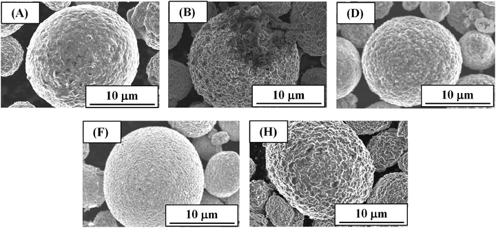
Fig. 3 shows the SEM images of (A) pristine NCA particles and (B, D, F and H) NCA particles exposed to water (in each case NCA particles (50 mg) were exposed to 5 mL water for 1 h and then dried at 130 °C for 1 h in a vacuum drying oven). The image B was obtained for the uncoated NCA particles, while the images D, F and H for TiOx-, Li2CO3- and TiOx/Li2CO3-coated NCA particles, respectively. When compared with SEM images of NCA particles prior to water treatment (Fig. S1†), we can see that the uncoated NCA (B) is damaged significantly due to the dissolution of the surface into water. The TEM image of the damaged NCA surface has been reported in our previous paper.12 On the damaged NCA surfaces, a Li-poor layer (2–3 nm in thickness) could be observed. On the other hand, the coated ones (D, F and H) seem not to be damaged. Fig. S1† shows SEM images of NCA particles prior to water treatment. The Li2CO3 coating (Fig. S1(E)†) smooths the NCA surface, while the surface coating by TiOx (Fig. S1(C)†) produces the rough surface. Also in the TiOx/Li2CO3 coating (Fig. S1(G)†), the NCA surface is rough probably reflecting TiOx coating and interesting the roughness is larger than in the case of TiOx coating.The TEM-EDX elemental mapping images of TiOx-coated NCA samples C-1–C-5 prepared at different spray conditions (Table 1) are shown in Fig. S2† where blue, red and green colors show the distribution of Co, Ni and Ti atoms, respectively, in the NCA particles. The overlapped elemental mapping images of Co, Ni and Ti indicate that NCA particle surfaces are Ti-riched and the degree of the Ti-coating is different depending on the spray conditions. Clearly, samples C-2 and C-5 have thicker TiOx layers on NCA particle surfaces. From the XRF experiments (Fig. S3†), samples C-2 and C-5 were found to have higher atomic ratios of Ti to Ni when compared with samples C-1, C-3 and C-4, suggesting that the former samples are coated with higher amount of TiOx. The thickness of TiOx coating on NCA particle surfaces is controlled by the concentration and spray speed of TTIP solution, i.e., the high concentration and spray speed of TTIP solution resulted in the increased thickness of TiOx. In addition, in order to confirm a thin and uniform coating of the NCA particles with TiOx layer, SEM-EDX images for typical particles of samples C-3 and C-4 which showed better cathode performance among the TiOx-coated NCA samples tested as described below were also obtained (Fig. S4†). They indicated that NCA particles are uniformly covered with TiOx layer even at the low coating amount of TiOx.
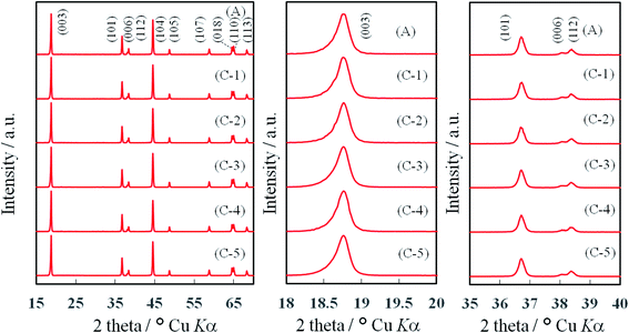
In order to identify the crystal structures of TiOx-coated layer and NCA, powder X-ray diffraction (pXRD) patterns of TiOx-coated NCA samples C-1∼C-5 were measured and the results are shown in Fig. 4. The pXRD profiles obtained matched that of a layered α-NaFeO2-type structure with the space group R![[3 with combining macron]](https://www.rsc.org/images/entities/char_0033_0304.gif) m,26 in which the Na sites are occupied by Li+ ions and the Fe sites by transition metal (Ni, Co and Al) ions. It was found that the pXRD peaks corresponding to the layered α-NaFeO2-type structure do not shift even at high degree of TiOx coating (e.g., samples C-2 and C-5), indicating that the TiOx layers formed on the NCA surfaces do not affect the crystal structure of the NCA particles themselves. On the other hand, the pXRD peaks for TiOx layer could not be observed in the pXRD patterns of NCA samples C-1–C-5 as found in recent studies12,19 in which the TiOx crystal structure is considered to grow “epitaxially” on the NCA particle surface based on the high angle annular-dark-field (HAADF)-scanning transmission electron microscopic (STEM) measurements.
m,26 in which the Na sites are occupied by Li+ ions and the Fe sites by transition metal (Ni, Co and Al) ions. It was found that the pXRD peaks corresponding to the layered α-NaFeO2-type structure do not shift even at high degree of TiOx coating (e.g., samples C-2 and C-5), indicating that the TiOx layers formed on the NCA surfaces do not affect the crystal structure of the NCA particles themselves. On the other hand, the pXRD peaks for TiOx layer could not be observed in the pXRD patterns of NCA samples C-1–C-5 as found in recent studies12,19 in which the TiOx crystal structure is considered to grow “epitaxially” on the NCA particle surface based on the high angle annular-dark-field (HAADF)-scanning transmission electron microscopic (STEM) measurements.
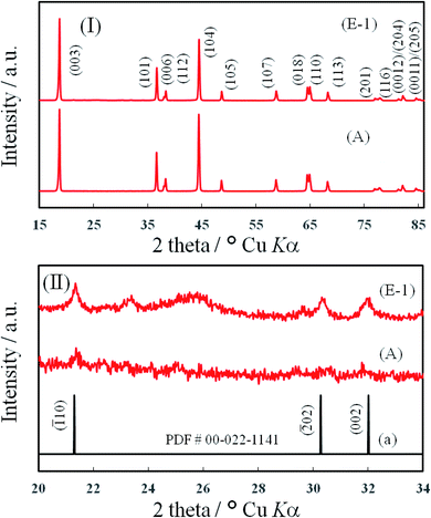
Fig. 5 (I) shows the pXRD patterns of Li2CO3-coated (E-1) and pristine (A) NCA samples. As mentioned above, the pXRD peaks for NCA particles could be observed, but there was no difference in pXRD peaks of both samples. In the expanded pXRD profile ((E-1) in (II)), as expected, three peaks for Li2CO3 could be observed clearly at 21.5, 30.1 and 32.0°. On the other hand, also in the pristine NCA, the peaks for Li2CO3 could be observed ((A) in (II)) probably because a small amount of Li2CO3 was formed by exposing the pristine NCA sample to air.
The pristine and Li2CO3-coated NCA samples had the Brunauer–Emmett–Teller (BET) surface areas of 0.11–0.12 m2 g−1, i.e., the NCA surface areas are almost the same in both samples. In order to calculate the surface coating (in a unit of mg cm−2) and layer thickness of Li2CO3, 0.155 m2 g−1 and 2.11 g cm−3 were used as a surface area of NCA particles and a density of Li2CO3 layer, respectively.27 From the Warder titration experiments, the Li2CO3-coated NCA samples prepared by bubbling CO2 gas for 1 h (E-1) and 7 days (E-4) were found to have the average Li2CO3 thicknesses of 16 and 22 nm, respectively. As can be seen from this, the thickness of Li2CO3 coating layer could be controlled by the period of bubbling of CO2 gas into the sample solutions. The Li2CO3 coating layer grew slowly over several hours.
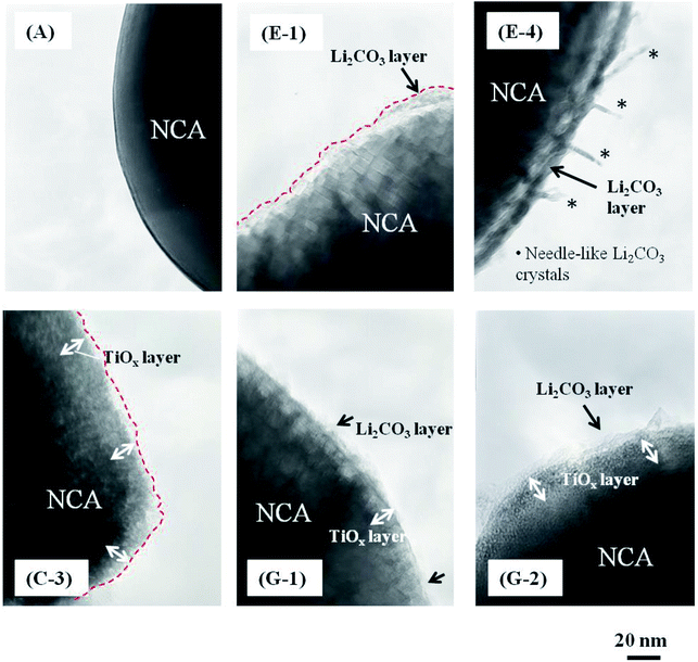
Fig. 6 shows the typical TEM images of (A) pristine, (E-1 and E-2) Li2CO3-coated, (C-3) TiOx-coated and (G-1 and G-2) TiOx/Li2CO3-coated NCA samples. The water-based Li2CO3-coated and TiOx/Li2CO3-coated NCA slurries were kept under CO2 atmosphere for 1 h (E-1 and G-1) and 7 days (E-4 and G-2). When the slurry solution of NCA particles was kept under CO2 atmosphere for 1 h (E-1 and G-1) and 7 days (E-4 and G-2), the Li2CO3 layer could be observed clearly on their surfaces as can be seen from the comparison with the TEM image of pristine NCA (A), i.e., the average thicknesses of the Li2CO3 layer were 13.5 (E-1) and 15.8 (E-4) nm. In addition, needle-like crystals were found to be formed when kept under CO2 atmosphere for 7 days (E-4) in the case of the water-based Li2CO3-coated NCA slurry. In this case, it is though that water invades into the coarse Li2CO3 layer and Li+ ions extracted from the NCA surfaces react with CO32− ions to form needle-like crystals of Li2CO3 on the Li2CO3 layer. The whole surface of NCA particles seems to be coated with the TiOx layer (Fig. 6 (C-3)). When the slurry composed of TiOx-coated NCA particles, water-based hybrid polymer binder (TRD202A), AB and CMC was kept under CO2 atmosphere for 1 h or 7 days, Li2CO3 layer may be formed on the TiOx layer (as it is not dense) as well as the TiOx-uncoated part in which LiOH as a residue on the NCA surface is the source of Li+ ions for the formation of Li2CO3. The average thicknesses of the Li2CO3 layer prepared on TiOx-coated NCA particles under CO2 atmosphere for 1 h (G-1) and 7 days (G-2) were 12.5 and 13.2 nm, respectively. However, needle-like crystals could not be observed being distinct from the case (E-4).
In order to confirm the formation of Li2CO3 layer on the NCA surface and TiOx layer, the STEM-EELS images of Li2CO3- and TiOx/Li2CO3-coated NCA samples were measured and the typical results are shown in Fig. 7–9. In the case of Li2CO3-coated NCA sample (E-1, Fig. 7), the signals corresponding to Li, O and C elements could be observed over the whole surface, indicating that the NCA surface is on a whole coated by the Li2CO3 layer. The average thickness of the Li2CO3 layer evaluated from the TEM image was ca. 15.7 nm, which was comparable to that calculated from the amount of Li2CO3 layer on the NCA surface estimated with a Wader titration using the density of Li2CO3 (d = 2.11 g cm−3).27 The STEM-EELS images of TiOx/Li2CO3-coated NCA particle (G-1, Fig. 8) confirmed Fig. 6 (G-1), i.e., the Li2CO3 layer is formed on the TiOx layer the average thickness of which was evaluated to be ca. 12.4 nm. From Fig. 9, it was further speculated that the needle-like crystals (shown in Fig. 6 (E-4)) observed after keeping the slurry solution containing pristine NCA particles under CO2 atmosphere for 7 days correspond to NiCO3 and Li2CO3. This fact suggests that the Li2CO3 layer formed on NCA particle surfaces is insufficient as a water-proof layer and as a result Ni2+ ions of NCA dissolve to form NiCO3. On the contrary, the TiOx layer on NCA particle surfaces inhibited the formation of the needle-like crystals under the same exposure to the CO2 atmosphere, indicating that the double coating of NCA surface by TiOx layer and then Li2CO3 layer is effective for giving a water-resistance to it.
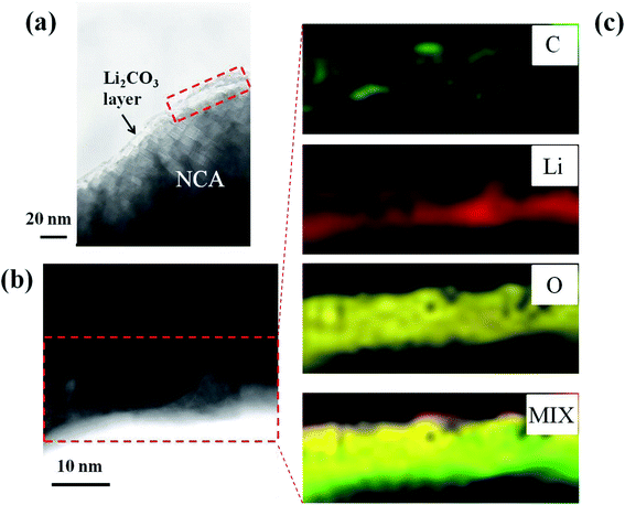 | ||
| Fig. 7 (a and b) Typical TEM images of Li2CO3 (CO2 bubbling for 1 h)-coated NCA (E-1) and (c) STEM-EELS mapping of C, Li and O elements and their mixed mapping. | ||
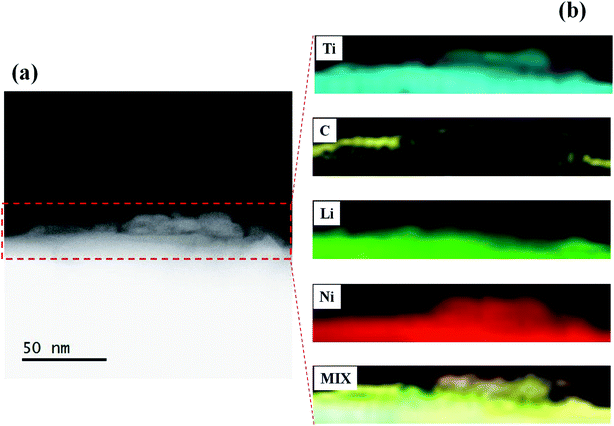 | ||
| Fig. 8 (a) Typical TEM image of TiOx/Li2CO3 (CO2 bubbling for 1 h)-coated NCA (G-1) and (b) STEM-EELS mapping of Ti, C and Li elements and their mixed mapping. | ||
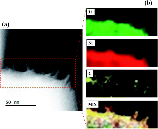 | ||
| Fig. 9 (a) Typical TEM image of Li2CO3 (CO2 bubbling for 7 days)-coated NCA (E-4) and (b) STEM-EELS mapping of Li, Ni and C elements and their mixed mapping. | ||
3.2 Charging/discharging performance tests with TiOx-, Li2CO3- and TiOx/Li2CO3-coated NCA materials
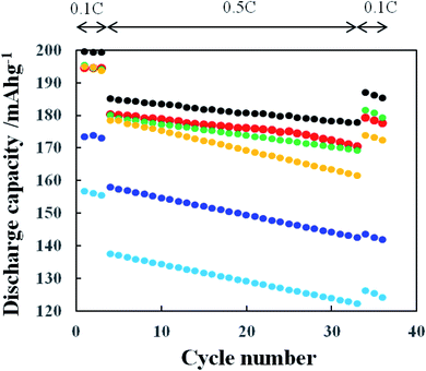
Fig. 10 shows the charging/discharging cycle performance obtained with the cathodes prepared from pristine NCA and TiOx-coated NCA samples C-1–C-5. The charge/discharge was conducted with the 0.1C-rate for first 3 cycles and then with 0.5C-rate for 30 cycles and again with 0.1C-rate for 3 cycles to confirm the initial charge/discharge performance. Clearly, the pristine NCA (A) cathode prepared with PVdF binder exhibited the highest discharge performance among the NCA samples tested. The cycle performance is in the order of pristine > sample C-1 = sample C-3 > sample C-4 > sample C-2 > sample C-5. The performance order of the TiOx-coated samples is similar to the order of atomic ratio of Ti to Ni (Fig. S3†), indicating that an excessive TiOx coating reduces the discharge capacity because the TiOx retards the intercalation/deintercalation of Li+ ion to/from the NCA cathode active material. The samples C-1 and C-3 exhibited the highest discharge performance among the TiOx-coated NCA samples, but their performance was a little inferior to that obtained with the pristine NCA. This small decrease in the discharge capacity of samples C-1 and C-3 is considered to reflect that they are damaged by contact with water in the course of their preparation. The NCA particle surfaces of samples C-1 and C-3 might be partly uncoated with the TiOx layer and/or coated with the coarse TiOx layer and consequently the NCA surface might partially suffer from the damage by contact with water. From the discharge capacities obtained at 0.1C-rate after 30 cycles at 0.5C-rate, the discharge capacity retentions (%) which are defined as (discharge capacity at the 34th cycle)/(discharge capacity at the 3rd cycle) × 100 of the pristine and TiOx-coated NCA samples C-1–C-5 were calculated to be 93, 92, 83, 94, 89 and 78%, respectively. The samples C-2 and C-5 coated with larger amount of TiOx are considered to suffer from larger damage by the discharge at 0.5C-rate because thicker TiOx layers of these samples more significantly retard the intercalation/deintercalation of Li+ ions. In addition, the high rate performance of TiOx-coated NCA samples was examined with the C-rate of 0.1, 0.2, 0.5, 1, 2, 3 and 5C (Fig. S5†). The samples C-1, C-3 and C-4 exhibited nearly the same performance as that obtained with the pristine NCA sample, while the samples C-2 and C-5 indicated significantly lower performance especially at higher C-rates. These results are similar to those obtained at the charging/discharging cycle tests at 0.1 and 0.5C (mentioned above). That is, the thick TiOx layer retarded actually the transfer of Li+ ions from/to cathode particle surfaces and consequently degraded the cathode performance. The samples C-1, C-3 and C-4 exhibited the charging/discharging cycle performance and high rate performance comparable to that obtained with the TiOx-coated NCA samples prepared by reacting TiOx-precursor with NCA surface in beaker,12,19 indicating that the present TiOx coating using a tumbling fluidized-bed granulating/coating machine enables to prepare the NCA particles coated with TiOx layer which rarely inhibit the transfer of Li+ ions from/to NCA particle surfaces by suitably adjusting the concentration of TiOx precursor solution which is sprayed in the reaction camber.The effect of Li2CO3 coating on NCA cathodes on their cycle performance was examined and the results are shown in Fig. 11, in which the slurry solution containing pristine NCA particles, TRD202A binder, CMC and conductive additive (AB) was kept under CO2 atmosphere for 1 h (E-1), 1 (E-2), 3 (E-3) and 7 (E-4) days. The reason why the CO2 treatment of 1 h to 7 days was examined in this study is that slurry solutions of electrode active materials are used, once prepared, typically for 7 days in the production line of commercially available LIBs. The discharge capacity decreased largely with increasing the CO2 treatment period. As mentioned above, longer CO2 treatment may produce thicker Li2CO3 and consequently leads to lower discharge capacity. Here we should also consider the damage of NCA particles by contact with water during the CO2 treatment for the Li2CO3 formation in the CO2-saturated aqueous slurry solution containing NCA particles. Interestingly, the NCA samples CO2-treated for 1 h (E-1) and 1 day (E-2) gave almost the same charge/discharge performance, although it is thought that the NCA sample CO2-treated for 1 h is less damaged by contact with water and the Li2CO3 layer formed is thinner compared with the 1 day CO2-treated one. Thus, under the present CO2 treatment condition the CO2 treatment of 1 h is enough to form the Li2CO3 layer.
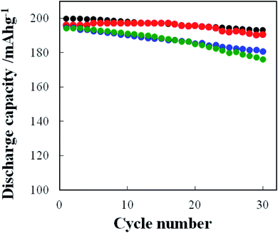
Fig. 12 shows the charge/discharge performance obtained with the cathodes prepared from the slurry containing pristine NCA, PVdF and AB as well as the water-based slurries containing TiOx-(C-3), Li2CO3(E-1)- or TiOx/Li2CO3(G-2)-coated NCA, TRD202A, CMC and AB. The pristine NCA (A) cathode prepared with PVdF binder exhibited the discharge capacities of 199 and 186 mA h g−1 at the 1st and 30th cycles, respectively and the discharge capacity retention was 93% at the 30th cycle. On the other hand, the discharge capacities of the TiOx-coated (Li2CO3-coated) NCA cathodes at the 1st and 30th cycles are 195 (196) and 177 (177) mA h g−1, respectively. The discharge capacity retentions for TiOx- and Li2CO3-coated NCA samples were 91 and 88% at the 30th cycles, respectively. The TiOx/Li2CO3-coated NCA cathode, which was prepared by keeping the water-based slurry for 7 days under CO2 atmosphere which means that the cathode was actually exposed to water for 7 days, exhibited the discharge capacities of 196 and 187 mA h g−1 at the 1st and 30th cycles, respectively and the discharge capacity retention of 95% at the 30th cycle. Thus, it is obvious that the TiOx/Li2CO3-coated NCA cathode is superior in both the discharge capacity and capacity retention to TiOx- and Li2CO3-coated NCA cathodes and the discharge capacity retention of the former is comparable to that of the pristine NCA cathode prepared with PVdF binder. The TiOx/Li2CO3-coated NCA cathodes gave, even though the NCA particles were exposed as the water-based slurry to water for 7 days, high charge/discharge capacities as a result of the surface double coating with TiOx and Li2CO3. In Fig. S6,† the SEM images of NCA particles on cathodes after the charging/discharging cycles of 30 times (done in Fig. 12) are shown. In this case, the NCA particles are covered with PVdF and AB or TRD202A, CMC and AB and thus their surfaces look rough due to the adsorption of PVdF and AB or TRD202A, CMC and AB. The difference of surface morphology could not be observed among the four samples examined. Also in the comparison of the SEM images of the four samples before and after the charging/discharging cycles of 30 times (the SEM images obtained after the cycles are not shown in this paper), the surface morphology change could not be observed. Moisture contents of the cathode electrodes after drying NMP or water solvent were measured with thermogravimetry (TG) (Experimental in ESI and Fig. S7†). The cathode (a) composed of pristine NCA, PVdF and AB did not exhibit the change in weight of its scratched layer, indicating that the water content is almost zero. The TiOx/Li2CO3-coated NCA (G-2) particles just after synthesis of the coated powder was showed a significantly large weight loss in the temperature region from 100 to 200 °C. However, the sample powder obtained from the cathode prepared with the TiOx/Li2CO3-coated NCA (G-2) particles exhibited only a very small loss, i.e., the weight loss was 0.23 wt% because the TiOx/Li2CO3-coated NCA particles on the cathode was dried well in the fabrication processes of cathodes. It can be considered that such a low content of water in the TiOx/Li2CO3-coated NCA cathode do not influence the cathode performance. The charge/discharge voltage–capacity curves of pristine (A), TiOx- (C-3), Li2CO3 (E-1)- and TiOx/Li2CO3 (G-2) -coated NCA cathodes are shown in Fig. S8.† These curves are, though there is a small difference in the charge/discharge capacity, typical for the NCA and show several small shoulders corresponding to the redox reaction of Co and Ni ions in NCA,27 indicating that the samples tested have the essentially same charge/discharge property except for the individual capacities.
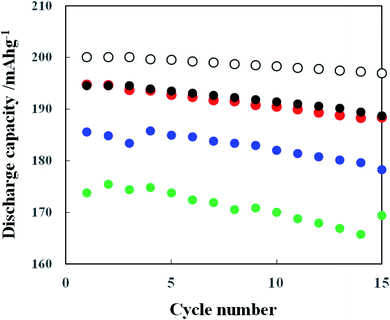
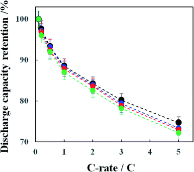
The rate performance of the above-mentioned cathodes of typical four types was examined and the results are shown in Fig. 13. As predicted, the pristine NCA (A) without a coating layer exhibited the highest C-rate performance. The rate performance of the coated NCA cathodes was in the order of the TiOx- (C-3), TiOx/Li2CO3- (G-2) and Li2CO3-coated (E-1) ones. These results are considered to reflect the different degree of the inhibition of Li+ ion transfer in the intercalation/deintercalation processes by the individual coatings. In order to check the conductivity change after the coating of NCA particles, the direct current internal resistance (DC-IR) drop which can be seen in the early stage of the discharging process was compared. Fig. S9-(a)† shows the discharge voltage-discharge capacity curves of pristine (A), TiOx- (C-3), Li2CO3 (E-1)- and TiOx/Li2CO3 (G-2)-coated NCA cathodes obtained at 5C-rate in the rate performance test of Fig. 13. The DC-IR drop can be related to the conductivity of coated NCA particles. In the enlarged discharge voltage-discharge capacity curves shown in Fig. S9-(b),† no difference in the DC-IR drop could be observed. Thus, the change of conductivity before and after the coating with TiOx, Li2CO3 and TiOx/Li2CO3 was not seen in the samples used in the rate performance test in Fig. 13. As mentioned in our previous paper,12 it is found that when thin TiOx coating layers are formed on NCA surface, they scarcely block the Li+ transportation through them. Certainly, also in Fig. 13, the rate performance of TiOx-coated NCA particles is almost the same as that of the pristine NCA particles within the experimental error. Li2CO3 coating, on the contrary, blocks somewhat the Li+ transportation through its layer because the discharge capacity retention obtained at the TiOx/Li2CO3-coated NCA cathode is lower than that obtained at the pristine and TiOx-coated ones. Therefore, we think that un-coated the gaps left by incomplete TiOx coating are infilled by Li2CO3 coating and thus the TiOx/Li2CO3-coated NCA cathode is inferior in the rate performance to the TiOx-coated NCA ones.
4. Conclusions
In this study, we originally proposed the surface double coating of NCA cathode with water-stable TiOx and Li2CO3 layers with a view of applying water-based binders to the preparation of the cathodes for LIBs because the use of water-based binders simplifies their production process and reduces their cost. NCA cathodes possess a high voltage and high charge/discharge capacity, but they are heavily damaged when contacted to water during their preparation processes. The NCA surface was coated firstly with TiOx layer by spraying TiOx precursor slurry using a tumbling fluidized-bed granulating/coating machine followed by sintering at 450 °C under argon atmosphere (producing TiOx-coated NCA particles) and then with Li2CO3 layer by bubbling CO2 gas in the TiOx-coated NCA aqueous slurry and consequently the NCA particles coated doubly with TiOx and Li2CO3 layers (TiOx/Li2CO3-coated NCA particles) were prepared. The TEM and STEM-EELS measurements confirmed that the whole surface of NCA particles is actually coated doubly with TiOx and Li2CO3 layers. The TiOx/Li2CO3-coated NCA cathode possessed a significantly higher charge/discharge performance compared with the TiOx- or Li2CO3-coated NCA cathodes and almost the same charge/discharge capacities as obtained at the NCA cathode prepared using the conventional organic solvent-based PVdF binder although the high rate discharge performance was a little inferior to the latter due to a small resistance of Li+ ion transfer through the coated layers. In addition, it should be noted that the present double coating procedure using a tumbling fluidized-bed granulating/coating machine and CO2 gas bubbling is promising at a viewpoint of the mass production of surface-coated cathode materials for LIBs using water-based binders. Further study along with this line is progress.Author contribution
T. W. and K. H. performed charge/discharge test and preparation of coated cathode materials. F. A. and T. G. characterized the synthesized materials with STEM, EELS and EDS. S. K., S. U. and H. L performed coating treatment of cathode materials with coating machine. Y. I. and F. M. (Nihon Kagaku Sangyo) performed a preparation of bare cathode material. J. W., T. O. and F. M. (Kanagawa University) wrote the manuscript, summarized the work.Conflicts of interest
The authors declare no competing financial interest.Acknowledgements
This work was financially supported by the Kato Foundation for Promotion of Science, Japan (T. Watanabe). This work was supported by NIMS microstructural characterization platform as a program of “Nanotechnology Platform” of the Ministry of Education, Culture, Sports, Science and Technology (MEXT), Japan.References
- M. Li, J. Lu, Z. Chen and K. Amine, 30 Years of Lithium-Ion Batteries, Adv. Mater., 2018, 30, 1800561 CrossRef PubMed.
- H. Lu, M. Behm, S. Leijonmarck, G. Lindbergh and A. Cornell, Flexible paper electrodes for Li-ion batteries using low amount of TEMPO-oxidized cellulose nanofibrils as binder, ACS Appl. Mater. Interfaces, 2016, 8, 18097–18106. CrossRef CAS PubMed.
- J. Xiea and Q. Zhang, Recent progress in rechargeable lithium batteries with organic materials as promising electrodes, J. Mater. Chem. A, 2016, 4, 7091–7106 RSC.
- M. Secchiaroli, S. Calcaterra, H. Y. Tran, S. J. Rezvani, F. Nobili, R. Marassi, M. W. Mehrens and S. Dsoke, Development of non-fluorinated cathodes based on Li3V1.95Ni0.05(PO4)3/C with prolonged cycle life: a comparison among Na-alginate, Na-carboxymethyl cellulose and poly(acrylic acid) binders, J. Electrochem. Soc., 2017, 164, A672–A683 CrossRef CAS.
- M. Kuenzel, D. Bresser, T. Diemant, D. V. Carvalho, G.-T. Kim, R. J. Behm and S. Passerini, Complementary strategies toward the aqueous processing of high-voltage LiNi0.5Mn1.5O4 lithium-ion cathodes, ChemSusChem, 2018, 11, 562–573 CrossRef CAS PubMed.
- T.-W. Kwon, J. W. Choi and A. Coskun, The emerging era of supramolecular polymeric binders in silicon anodes, Chem. Soc. Rev., 2018, 47, 2145–2164 RSC.
- Y. Shi, X. Zhou and G. Yu, Material and structural design of novel binder systems for high-energy, high-power lithium-ion batteries, Acc. Chem. Res., 2017, 50, 2642–2652 CrossRef CAS PubMed.
- J.-T. Li, Z.-Y. Wu, Y.-Q. Lu, Y. Zhou, Q.-S. Huang, L. Huang and S.-G. Sun, Water soluble binder, an electrochemical performance booster for electrode materials with high energy density, Adv. Energy Mater., 2017, 7, 1701185 CrossRef.
- D. L. Wood III, J. Li and C. Daniel, Prospects for reducing the processing cost of lithium ion batteries, J. Power Sources, 2015, 275, 234–242 CrossRef.
- Z. Chena, G.-T. Kim, D. Chao, N. Loeffler, M. Copley, J. Lin, Z. Shen and S. Passerini, Toward greener lithium-ion batteries: aqueous binder-based LiNi0.4Co0.2Mn0.4O2 cathode material with superior electrochemical performance, J. Power Sources, 2017, 372, 180–187 CrossRef.
- T. Tanabe, T. Gunji, Y. Honma, K. Miyamoto, T. Tsuda, Y. Mochizuki, S. Kaneko, S. Ugawa, H. Lee, T. Ohsaka and F. Matsumoto, Preparation of water-resistant surface coated high-voltage LiNi0.5Mn1.5O4 cathode and its cathode performance to apply a water-based hybrid polymer binder to Li-ion batteries, Electrochim. Acta, 2017, 224, 429–438 CrossRef CAS.
- T. Tanabe, Y. B. Liu, K. Miyamoto, Y. Irii, F. Maki, F. Maki, T. Gunji, S. Kaneko, S. Ugawa, H. Lee, T. Ohsaka and F. Matsumoto, Synthesis of water-resistant thin TiOx layer-coated high-voltage and high-capacity LiNiaCobAl1−a−bO2 (a > 0.85) cathode and its cathode performance to apply a water-based hybrid polymer binder to Li-ion batteries, Electrochim. Acta, 2017, 258, 1348–1355 CrossRef CAS.
- K. Notake, T. Gunji, S. Kosemura, Y. Mochizuki, T. Tanabe, S. Kaneko, S. Ugawa, H. Lee and F. Matsumoto, The application of a water-based hybrid polymer binder to a high-voltage and high-capacity Li-rich solid-solution cathode and its performance in Li-ion batteries, J. Appl. Electrochem., 2016, 46, 267–278 CrossRef CAS.
- J. Paulsen and J. H. Kim, High Nickel Content Cathode Material Having Low Soluble Base Content, US Pat., US2014/0054495A1, 2013 Search PubMed.
- K. Soeda, M. Yamagata and M. Ishikawa, Alginic Acid as a New Aqueous Slurry-Based Binder for Cathode Materials of LIB, ECS Trans., 2015, 64, 13–22 CrossRef CAS.
- M. Morishita, T. Mukai, T. Sakamoto, M. Yanagida and T. Sakai, Improvement of Cycling Stability at 80 °C for 4 V-Class Lithium-Ion Batteries and Safety Evaluation, J. Electrochem. Soc., 2013, 160(8), A1311–A1318 CrossRef CAS.
- K. Kimura, T. Sakamoto, T. Mukai, Y. Ikeuchi, N. Yamashita, K. Onishi, K. Asami and M. Yanagida, Improvement of the cyclability and coulombic efficiency of Li-ion batteries using Li[Ni0.8Co0.15Al0.05]O2 cathode containing an aqueous binder with pressurized CO2 gas treatment, J. Electrochem. Soc., 2018, 165, A16–A20 CrossRef CAS.
- K. Kimura, K. Onishi, T. Sakamoto, K. Asami and M. Yanagida, Achievement of the high-capacity retention rate for the Li[Ni0.8Co0.15Al0.05]O2 (NCA) cathode containing an aqueous binder with CO2 gas treatment using the cavitation effect (CTCE), J. Electrochem. Soc., 2019, 166, A5313–A5317 CrossRef CAS.
- Y. Liu, T. Tanabe, Y. Irii, F. Maki, T. Tsuda, T. Gunji, S. Ugawa, Y. Asai, H. Lee, T. Ohsaka and F. Matsumoto, Optimization of Synthesis Condition of Water-Resistant and Thin Titanium Oxide Layer-Coated Ni-rich Layered Cathode Materials and Their Cathode Performance, J. Appl. Electrochem., 2019, 49, 99–110 CrossRef CAS.
- W. S. Kim, K. I. Chung, J. H. Cho, D. W. Park, C. Y. Kim and Y. K. Choi, Studies of a solid electrolyte interface coated with Li2CO3 on the carbon electrode in Li-ion batteries, J. Ind. Eng. Chem., 2003, 9, 699–703 CAS.
- X. Dai, A. Zhou, J. Xu, Y. Lu, L. Wang, C. Fan and J. Li, Extending the high-voltage capacity of LiCoO2 cathode by direct coating of the composite electrode with Li2CO3 via magnetron sputtering, J. Phys. Chem. C, 2016, 120, 422–430 CrossRef CAS.
- Z. Chen, C. Liu, G. Sun, X. Kong, S. Lai, J. Li, R. Zhou, J. Wang and J. Zhao, Electrochemical degradation mechanism and thermal behaviors of the stored LiNi0.5Co0.2Mn0.3O2 cathode materials, ACS Appl. Mater. Interfaces, 2018, 10, 25454–25464 CrossRef CAS PubMed.
- T. Hayashi, J. Okada, E. Toda, R. Kuzuo, N. Oshimura, N. Kuwata and J. Kawamura, Degradation Mechanism of LiNi0.82Co0.15Al0.03O2 positive electrodes of a lithium-ion battery by long-term cycling test, J. Electrochem. Soc., 2014, 161, A1007–A1011 CrossRef CAS.
- https://www.powrex.co.jp/mp-series-en.
- R. de Levie, Aqueous Acid-base Equilibria and Titrations, Oxford University Press, 1st edn, 1999 Search PubMed.
- M. Bichon, D. Sotta, N. Dupré, E. D. Vito, A. Boulineau, W. Porcher and B. Lestriez, Study of immersion of LiNi0.5Mn0.3Co0.2O2 material in water for aqueous processing of positive electrode for Li-ion batteries, ACS Appl. Mater. Interfaces, 2019, 11, 18331–18341 CrossRef CAS PubMed.
- R. Robert and P. Novák, Switch of the charge storage mechanism of LixNi0.80Co0.15Al0.05O2 at overdischarge conditions, Chem. Mater., 2018, 30, 1907–1911 CrossRef CAS.
Footnote |
| † Electronic supplementary information (ESI) available. See DOI: 10.1039/d0ra00197j |
| This journal is © The Royal Society of Chemistry 2020 |

