 Open Access Article
A highly stretchable strain sensor based on CNT/graphene/fullerene-SEBS
Shirui Pan,
Zhen Pei,
Zhu Jing,
Jianqiao Song,
Wendong Zhang,
Qiang Zhang* and
Shengbo Sang *
*
MicroNano System Research Center, College of Information and Computer & Key Laboratory of Advanced Transducers and Intelligent Control System of Ministry of Education and Shanxi Province, Taiyuan University of Technology, Taiyuan, 030024, China. E-mail: zhangqiang01@tyut.edu.cn; sunboa-sang@tyut.edu.cn
First published on 18th March 2020
Abstract
Recently, highly stretchable strain sensors have attracted considerable attention. Identifying alternatives to sensitive unit materials and flexible substrates is critical in the fabrication of sensors. Herein, a trinary hybrid carbon material consisting of carbon nanotubes (CNTs), graphene, and fullerene was chosen due to its dense interconnections and robust mechanism. Additionally, the cost-effective fabrication of styrene ethylene butylene styrene (SEBS) provides a platform for the strong adhesion of substrates, which contributes to the strong interaction between the substrates and the sensitive unit materials. Furthermore, the intrinsically high elasticity of SEBS allows the sensors to endure large stretching ranges. Owing to the above-mentioned merits, the fabricated sensor based on CNT/graphene/fullerene-SEBS has a high conductivity of 5.179 S m−1, a moderate gauge factor (GF) of 15, an optimum stretching range of 203%, a linearity of 136% (R2 = 0.998), and adaptive-rate repeatability, which reveals its potential in the fields of human motion monitoring and scalable applications.
1 Introduction
With the development of smart technology, flexible electronic devices have been applied in various fields, including health monitoring,1 human motion,2 flexible photoelectrics,3 artificial muscle design,4 and intelligent weaving.5 Due to better stretchability,6,7 flexibility,8,9 skin adaptability and sensitivity of flexible electronic devices,10–13 much attention has been given to the potential applications of highly stretchable, linear,14,15 and electrically conductive strain sensors. In particular, flexible substrates with wide stretching ranges16–18 and hybrid sensitive unit nanomaterials are still hot topics in scientific research.In general, flexible sensors are mainly composed of two parts, sensitive unit materials and flexible substrates. Traditionally, carbon/metal nanomaterials and polydimethylsiloxane (PDMS), as common sensitive unit materials and flexible substrates, respectively, have been widely applied in flexible strain sensors. Metal nanomaterials were extensively studied due to their excellent electrical conductivity and gauge factor (GF).19–22 Amjadi et al. reported a highly stretchable and sensitive strain sensor based on Ag nanowire (AgNW)/PDMS with a stretchability of around 70% and a GF of ≈14.23 Kim et al. introduced a type of highly sensitive stretchable strain sensor based on Ag flakes/Ag nanoparticles (AgNPs), which reached a strain range of 80% and a GF of 7.1.24 Additionally, carbon nanomaterials were highly reported because of their outstanding consistency, excellent mechanical properties, and good electrical conductivity.25–28 CNT, a typical delegate of the 1-dimensional (1-D) carbon nanomaterial family, can withstand a wide range of stretching without causing fracture of the interconnections due to its high aspect ratio. Due to this characteristic, 1-D carbon nanomaterials also show a low relative resistance when stretched. Graphene, a 2-dimensional (2-D) carbon material, has a low aspect ratio, so it also performed a relatively large relative resistance and easy disconnection. Because of this, there has always been a contradiction between stretchability and gauge factor (GF) in CNT–PDMS and graphene–PDMS based sensors. For example, Yamada et al. studied a stretchable strain sensor based on CNTs, which exhibited high consistency and endured a 280% strain range with a dramatically low GF of around 0.82.29 Jeong et al. reported highly stretchable and sensitive strain sensors based on graphene with a moderate stretchability of 70% and a high GF of up to 29.30 To balance the characteristics of the two material systems, it was feasible to combine CNTs with graphene to resolve the contradiction between stretchability and GF. Cai et al. reported that under the synergistic mechanism of CNTs and graphene foam, experimental results indicated that the sensor had a large stretching range (85%) and high gauge factor (GF ≈ 20.5).31 In order to further defer the crack propagation of the sensitive unit materials and ensure the normal operation of the sensor under huge enforced strain, fullerene, as a 0-dimensional (0-D) carbon material, was used to efficiently hinder the breakage and lubricate the adjacent sliding of the 2-D graphene layers.32 This inspired us to offset the insufficient stretching range. Due to the moderate stretching ranges of PDMS, much effort was focused on adopting other substrates including thermoplastic urethane (TPU) and natural rubber.33,34 However, complex preparation processes involving chemical reagents are in opposition to environmentally friendly considerations. Thus, tolerable-strain merits and easy preparation protocols are needed to meet the demand for substrates. Zunfeng et al. took advantage of the high elasticity of SEBS to fabricate superelastic electronic sensors,35 which provided us with research ideas for manufacturing highly stretchable sensors (Table 1).
| Sensitive unit materials | Substrate | Strain | Max linearity | GF | Reference |
|---|---|---|---|---|---|
| AgNW | PDMS | 70% | Up to 50% | 2–14 | 23 |
| Ag fakes/AgNPs | PDMS | 80% | N/A | 7.1 | 24 |
| CNT | PDMS | 280% | Up to 140% | 0.82 | 29 |
| Graphene | PDMS | 70% | N/A | 15–29 | 30 |
| CNT/graphene | PDMS | 85% | N/A | 20.5 | 31 |
| AgNW/graphene/fullerene | Polyurethane | 62% | 32% | 2392.9 | 32 |
| Graphene | TPU | 30% | N/A | 0.78–17.7 | 33 |
| CNT | Natural rubber | 100% | N/A | 43.5 | 34 |
| CNT | SEBS | 700–1320% | N/A | 0.005 | 35 |
| CNT/graphene/fullerene | SEBS | 203% | Up to 136% | 15 | This work |
Herein, based on the excellent consistency of CNTs, good conductivity of graphene, and the spherical lubrication of fullerene, trinary hybrid carbon nanomaterials CNT/graphene/fullerene were selected as sensitive unit materials in order to provide excellent conductivity and large strain ranges. SEBS-based flexible substrates were fabricated by mixing and heating liquid paraffin with fixed quantities of SEBS powder, which proved to be an easy and cost-effective fabrication method. The substrate fabricated from the hybrid SEBS powder and liquid paraffin possessed strong adhesion properties, which gave rise to a strong interaction with sensitive unit materials. As a result, inherent adhesive merit was proved by sticking to various materials and tape testing. By comparing the electrical performance of single CNT-SEBS based sensors, binary CNT/graphene-SEBS based sensors and the trinary CNT/graphene/fullerene-SEBS based sensor, we concluded that the trinary CNT/graphene/fullerene-SEBS based sensor had the highest conductivity and stretching and linearity ranges but a relatively moderate gauge factor (GF). Moreover, cyclic tests with different rates and stretching ranges were performed to demonstrate stable repeatability and reproduction. Finally, human monitoring measurements could be performed in real time while blowing and bending wrists and fingers, indicating the potential for future applications.
2 Experiment
2.1 Fabrication of flexible strain sensors
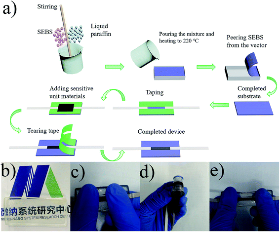
A schematic of the sensor is shown in Fig. 1(a). First, the SEBS (TSRC Nantong Industries Co., Ltd.) powder and liquid paraffin (Shangqiu Liangfeng Health Products Co., Ltd.) were mixed in a certain mass ratio (1![[thin space (1/6-em)]](https://www.rsc.org/images/entities/char_2009.gif) :
:![[thin space (1/6-em)]](https://www.rsc.org/images/entities/char_2009.gif) 3 in this experiment) and stirred in a beaker to obtain a uniform mixture. A certain amount of the mixture was placed into a vector with a length, width, and height of 60 × 30 × 20 mm3, respectively. The ark vector was placed in a high temperature resistance furnace (Shanghai Boxun Industrial Co., Ltd. Medical Equipment Factory) and heated to 220 °C for 30 minutes. Finally, it was placed at room temperature until the molten SEBS cooled, solidified, and peeled off from the porcelain ark vector. Different proportions of the sensitive unit materials (1
3 in this experiment) and stirred in a beaker to obtain a uniform mixture. A certain amount of the mixture was placed into a vector with a length, width, and height of 60 × 30 × 20 mm3, respectively. The ark vector was placed in a high temperature resistance furnace (Shanghai Boxun Industrial Co., Ltd. Medical Equipment Factory) and heated to 220 °C for 30 minutes. Finally, it was placed at room temperature until the molten SEBS cooled, solidified, and peeled off from the porcelain ark vector. Different proportions of the sensitive unit materials (1![[thin space (1/6-em)]](https://www.rsc.org/images/entities/char_2009.gif) :
:![[thin space (1/6-em)]](https://www.rsc.org/images/entities/char_2009.gif) 1 for CNT/graphene and 1
1 for CNT/graphene and 1![[thin space (1/6-em)]](https://www.rsc.org/images/entities/char_2009.gif) :
:![[thin space (1/6-em)]](https://www.rsc.org/images/entities/char_2009.gif) 1
1![[thin space (1/6-em)]](https://www.rsc.org/images/entities/char_2009.gif) :
:![[thin space (1/6-em)]](https://www.rsc.org/images/entities/char_2009.gif) 0.23 for CNT/graphene/fullerene) dissolved in 30 mL of deionized water were placed in an ultrasonic cell pulverizer (Branson ultrasonic Shanghai Co., Ltd.) for 40 min at 40% power. CNT was purchased from Chengdu Organic Chemistry Co., Ltd., the Chinese Academy of Sciences. Graphene was purchased from Shenzhen Guoheng Technology Co., Ltd and fullerene was purchased from Shanghai Macklin Biochemical Co., Ltd. Eventually, the fabricated materials were evaporated to dryness in air and ground into a powder. The prepared SEBS substrate was spread on a Petri dish and double transparent tape stripes were placed symmetrically on both sides of the long axis of the substrate leaving a width of 5 mm in the middle. Then, two conductive tapes were symmetrically attached along both ends of the long axis with a length of 18 mm reserved in the middle. Next, the sensitive unit materials were homogeneously filled in the middle groove of around 0.25 mm in thickness. Eventually, the sensor fabrication was completed after the transparent tape stripes on both sides were torn off. Fig. 1(b) represents the finished SEBS substrate with an approximate length, width, and height of 60 × 30 × 2 mm3. Fig. 1(c), (d), and (e) represent the state of the sensor under initial, bending, and stretching conditions, respectively.
0.23 for CNT/graphene/fullerene) dissolved in 30 mL of deionized water were placed in an ultrasonic cell pulverizer (Branson ultrasonic Shanghai Co., Ltd.) for 40 min at 40% power. CNT was purchased from Chengdu Organic Chemistry Co., Ltd., the Chinese Academy of Sciences. Graphene was purchased from Shenzhen Guoheng Technology Co., Ltd and fullerene was purchased from Shanghai Macklin Biochemical Co., Ltd. Eventually, the fabricated materials were evaporated to dryness in air and ground into a powder. The prepared SEBS substrate was spread on a Petri dish and double transparent tape stripes were placed symmetrically on both sides of the long axis of the substrate leaving a width of 5 mm in the middle. Then, two conductive tapes were symmetrically attached along both ends of the long axis with a length of 18 mm reserved in the middle. Next, the sensitive unit materials were homogeneously filled in the middle groove of around 0.25 mm in thickness. Eventually, the sensor fabrication was completed after the transparent tape stripes on both sides were torn off. Fig. 1(b) represents the finished SEBS substrate with an approximate length, width, and height of 60 × 30 × 2 mm3. Fig. 1(c), (d), and (e) represent the state of the sensor under initial, bending, and stretching conditions, respectively.
2.2 Characterization and properties testing of sensors
The topography of the sensitive unit materials and substrate were characterized by scanning electron microscopy (SEM Hitachi Corporation, Tokyo, Japan) employed at 15 kV and transmission electron microscopy (TEM JEOL Corporation, Tokyo, Japan) under 200 kV. A tensile test was performed on a flexible substrate prepared by mixing different SEBS powders and paraffin oil. Primarily, a digital display force gauge was separately fixed on a self-assembled optical displacement platform to test the relationship between stress and strain. Then, the probes of a digital source meter (Keithley 2400) were clamped onto the sensor to measure its I–V curve, conductivity, and relative resistance to strain. Additionally, the sensor was mounted on an electric cycle motor for cyclic testing at different stretching lengths and speeds. Finally, blowing, finger bending, and wrist bending detection was tested.3 Results and discussion
3.1 Characterization of the sensor
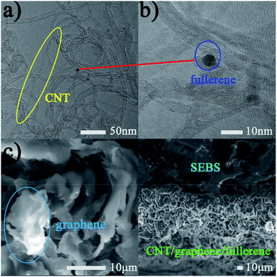
The geometry of the hybrid CNT/graphene/fullerene is exhibited in Fig. 2(a–c). The topography of CNTs and fullerene under TEM could be clearly observed. The size of the tubular CNTs was around 10 μm × 10 nm. The diameter of the spherical fullerene was 5 nm. The blue circle in Fig. 2(c) presents a SEM image (under 2500 times magnification) of the lamellar structure of graphene, where the graphene has a sheet diameter of approximately 12 μm. Fig. 2(d) represents a cross-section of SEBS and the sensitive unit materials. Fig. 2(a–c) demonstrate the composition and geometric topography of the sensitive unit materials. Fig. 2(d) displays a strong interaction between SEBS and the sensitive unit materials, which arises from the inherently adhesive surface of SEBS.3.2 Performance test of the substrate
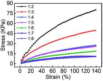
We then explored the effect of different ratios of SEBS powder and liquid paraffin on the mechanical properties of the prepared SEBS substrate. A digital display force gauge was fixed on the self-assembled optical displacement platform to understand the relation between stress and strain in the substrates with different mixing ratios. For a certain proportion of the substrates shown in Fig. 3, as the applied strain increased the stress ascended correspondingly, which revealed a directly proportional relationship. Secondly, under the same strain conditions, the stress gradually decreased as the liquid paraffin mass percentage increased. In summary, the toughness of the substrate produced reduced due to the loss of SEBS powder. In order to endow the substrate with a larger stretching range and better toughness, the 1![[thin space (1/6-em)]](https://www.rsc.org/images/entities/char_2009.gif) :
:![[thin space (1/6-em)]](https://www.rsc.org/images/entities/char_2009.gif) 3 blend ratio of the substrates was chosen for this experiment to ensure both transparency and consistency.
3 blend ratio of the substrates was chosen for this experiment to ensure both transparency and consistency.
The flexible substrate demonstrated good adhesion to different materials. As shown in Fig. 4 (a–d), the substrate could adhere to a plastic centrifuge tube, polylactic acid, an iron long tail clip, and a glass beaker, respectively. Basically, the ideal adhesion properties promoted this combination of sensitive unit materials and flexible substrates. In order to compare the adhesion of the SEBS substrate to a traditional substrate, tape tests were utilized. The adhesion of SEBS and PDMS to sensitive unit materials was studied. SEBS and PDMS with the same length, width, and height of 60 mm, 30 mm, and 2 mm were used as samples in the experiment. The black and red curves in Fig. 4(e) represent the relative resistance at different tear times of the PDMS-based and SEBS-based sensors. It can be observed that tearing removed the sensitive unit materials from PDMS after 3 attempts and the relative resistance suddenly ascended to the open state. Comparatively, stable relative resistance could be maintained after tearing 11 times on SEBS. This is attributed to the excellent adhesive properties of the sensitive unit materials, which could comply with the deformation of the substrates. This great protective mechanism mitigates the impact of external environmental factors for practical applications.
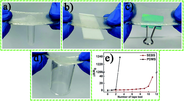 | ||
| Fig. 4 The SEBS substrate film adhered to (a) a plastic centrifuge tube, (b) polylactic acid, (c) an iron long tail clip, and (d) a glass beaker. (e) Tape test results. | ||
3.3 Performance test of sensors
The voltage–current (I–V) characteristics of the conductivity of the sensors based on CNTs, CNT/graphene, and CNT/graphene/fullerene can be observed in Fig. 5(a–c). Within the voltage range of −1000 mV to 1000 mV, current and voltage showed a perfectly linear dependence and favorable resistance characteristics. Conductivity (σ) can be calculated by the formula σ = L/RS, in which L, R, and S represent the length, resistance, and cross-sectional area of the sensitive unit materials, respectively. The conductivities of the sensors in the initial state were calculated from the data to be 1.684 S m−1, 2.932 S m−1 and 5.179 S m−1, as displayed in Fig. 5(d). By comparing the conductivity of the CNT and CNT/graphene-based sensors, we evidently found that the CNT/graphene-based sensor has a higher conductivity than the single CNT-based sensor, which proves that the addition of graphene boosts the conductivity of the materials. Notably, fullerenes, as 0-D spherical materials, have good lubricating properties and contribute to the reduction of crack propagation in sensitive unit materials and act as interlayer lubrication to bridge CNT and graphene units. Hence, fullerene materials were added to the CNT/graphene hybrid materials. It was found that the conductivity of the sensor based on CNT/graphene/fullerene materials was higher than that of the sensor based on CNT/graphene. The results demonstrated that fullerene acting as an electrical bridge endowed CNTs and graphene with better conductive paths, effectively enhancing the conductivity.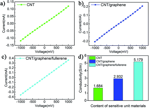 | ||
| Fig. 5 I–V characteristic curve of the (a) CNT-based sensor, (b) CNT/graphene-based sensor, and (c) CNT/graphene/fullerene-based sensor. (d) Histogram of conductivity. | ||
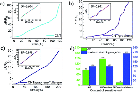
Next, the relative resistance of the three sensors was researched under relative strain ranges. The gauge factor (GF) can be calculated using the equation
The principle of structural transformation of the sensitive unit materials during the stretching process was revealed in Fig. 7. In the initial state, the three sensitive unit materials were closely distributed. In the CNT-based sensor, the conductive cross-links mainly existed in the contact resistance and the tunneling resistance between the CNT units. In the CNT/graphene-based sensor, the connecting resistance between CNT and graphene served as an essential electrical bridge. Similarly, in the sensor based on CNT/graphene/fullerene, the interconnections are primarily present in the bonding of CNTs, graphene, and fullerene. In the case of a strain range of 60%, the cross-links in the CNT-based sensor between the CNT units were partially broken, causing a surge in the resistance. Similarly, the connection resistance between the CNT units and graphene and the layer resistance of the graphene were vulnerable to disruption. Notably, the sheet-like structure of graphene is more susceptible to crack propagation. Therefore, the relative resistance of the CNT/graphene sensor under the same strain conditions was higher than that of the CNT-based sensor. In the end, due to fullerene's inherent lubricity, it was possible to effectively reduce interlaminar friction and crack generation in graphene and ensure a conductive path between CNT and CNT/graphene, resulting in the lowest rate of change than previous sensors. Under the 120% strain condition, the connection resistance between the CNT-based and CNT/graphene-based sensors was almost in the critical state of fracture and the relative resistance reached a maximum. In comparison, the sensor based on CNT/graphene/fullerene possessed a large stretching range and a low resistance change rate because of interlayer lubrication and the anti-cracking mechanism of fullerene.
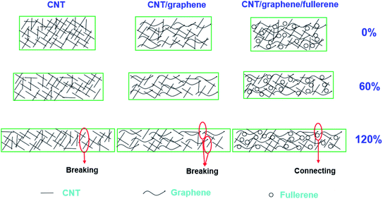 | ||
| Fig. 7 Schematic diagram of the variation principle of the CNT-based sensor, CNT/graphene-based sensor, and the CNT/graphene/fullerene-based sensor under a strain of 0, 60%, and 120%. | ||
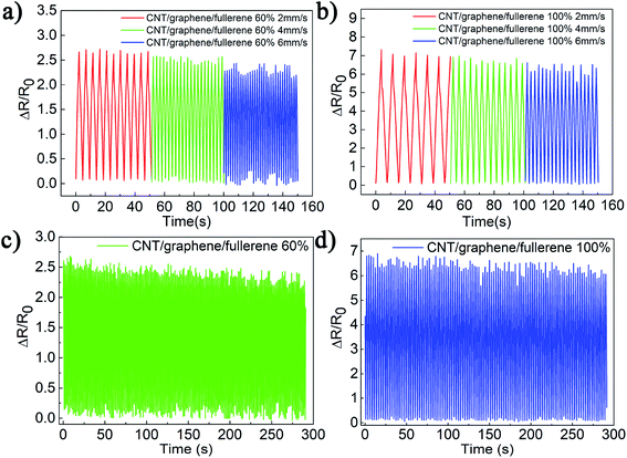
In order to investigate the stability of relative resistance based on the CNT/graphene/fullerene sensor under different strain ranges and tensile rates, the sensors were mounted on an electric cycle motor and the results were displayed in real time on a digital source meter. As shown in Fig. 8(a), the strain range was set to 60% and the sensor was uniformly stretched at a rate of 2 mm s−1, 4 mm s−1, and 6 mm s−1. The results show the resistance changes during the cyclic tensile test at three different rates, and a very stable maximum relative resistance of about 2.5 was recorded. Similarly, the sensor in Fig. 8(b) was tested at a rate of 2 mm s−1, 4 mm s−1, and 6 mm s−1 under 100% strain and the measurements showed that the maximum relative resistance was approximately 7. For long-time cyclic tests, the sensors were subjected to 60% and 100% strain ranges at a 6 mm s−1 stretching rate. As displayed in Fig. 8(c and d), the properties were maintained even after a number of repetitive cycles (187 and 112 within 300 seconds). As can be seen from the results, the maximum relative resistance was basically constant under long-term repetition.
In order to achieve real-time human monitoring of movement with the sensors, we conducted three sets of application tests. Firstly, the two ends of the sensor were fixed on two horizontal displacement platforms and blowing was preformed against the center of the sensor. Due to the bending angle (θa) generated by blowing on the sensor (Fig. 9(a)), the sensitive unit material was slightly deformed and the measured maximum resistance change rate was approximately 1.4. Secondly, due to the increased curvature (θb) produced by the bending of the wrist in Fig. 9(b), many cracks were observed in the sensitive unit materials, resulting in a larger relative resistance of around 12. Finally, a finger bending test was performed since the finger has the most flexible range of motion. As seen in Fig. 9(c), the bending angle (θc) was the largest due to huge crack propagation and the largest relative resistance of approximately 25 was observed. Therefore, it was shown that the sensor based on CNT/graphene/fullerene-SEBS can effectively monitor human movement in real time, which proves the practical value of this research for future strain sensor technologies.
4 Conclusion
In this paper, CNT/graphene/fullerene-based sensors were employed as flexible strain sensors and were fabricated from different sensitive unit materials based on SEBS. First, we performed SEM and TEM characterization of the sensor to observe the micro appearance and geometric architecture of the sensitive unit materials and substrates, which confirmed the composition of the sensitive unit material and the close combination of the sensitive unit materials with the substrate. Then we conducted performance tests on the substrate. The mechanical properties of the flexible substrates were explored by mixing different SEBS powders with liquid paraffin and a ratio of 1![[thin space (1/6-em)]](https://www.rsc.org/images/entities/char_2009.gif) :
:![[thin space (1/6-em)]](https://www.rsc.org/images/entities/char_2009.gif) 3 was selected as the substrate for further experiments. Through the adhesive experiment, the SEBS-based substrate was shown to demonstrate a perfect adhesion effect, which was advantageous for making sensitive unit materials conform to deformation inseparably. Finally, an electrical performance test was performed on the sensor. I–V characteristics and strain-resistance regulation of the sensitive unit materials based on CNTs, CNT/graphene, and CNT/graphene/fullerene were separately discussed to explore the impact of the CNT/graphene/fullerene synergetic mechanism. It was shown that the CNT/graphene/fullerene-SEBS based sensor maintained an ideal conductivity of 5.179 S m−1 and a maximum sensing range of up to 203% with a fitted linearity of 136% (R2 = 0.998). The comparison experiment confirmed that the sensors based on CNT/graphene/fullerene could endure long-term cyclic tests and retain stable rate-independent repeatability and reproduction. In order to realize the practical applications of the sensor, three human monitoring applications causing different bending curvatures were tested separately, which is expected to inspire further research in the field of human motion monitoring.
3 was selected as the substrate for further experiments. Through the adhesive experiment, the SEBS-based substrate was shown to demonstrate a perfect adhesion effect, which was advantageous for making sensitive unit materials conform to deformation inseparably. Finally, an electrical performance test was performed on the sensor. I–V characteristics and strain-resistance regulation of the sensitive unit materials based on CNTs, CNT/graphene, and CNT/graphene/fullerene were separately discussed to explore the impact of the CNT/graphene/fullerene synergetic mechanism. It was shown that the CNT/graphene/fullerene-SEBS based sensor maintained an ideal conductivity of 5.179 S m−1 and a maximum sensing range of up to 203% with a fitted linearity of 136% (R2 = 0.998). The comparison experiment confirmed that the sensors based on CNT/graphene/fullerene could endure long-term cyclic tests and retain stable rate-independent repeatability and reproduction. In order to realize the practical applications of the sensor, three human monitoring applications causing different bending curvatures were tested separately, which is expected to inspire further research in the field of human motion monitoring.
Conflicts of interest
The authors declare there are no conflicts of interest.Acknowledgements
This work is supported in part by the National Key Research and Development Project of China (No. 2019YFB1310200), the National Natural Science Foundation of China (No. 61703298 and 51975400), and the Shanxi University Innovation Project of China (RD1900000640).References
- Q. Hua, J. Sun, H. Liu, R. Bao, R. Yu, J. Zhai, C. Pan and Z. L. Wang, Nat. Commun., 2018, 9, 244 CrossRef PubMed.
- G. Cai, J. Wang, K. Qian, J. Chen, S. Li and P. S. Lee, Adv. Sci., 2017, 4, 1600190 CrossRef PubMed.
- H. Li, D. Yang, T. Zhang, P. Zhang, F. Wang, C. Qin, R. Yang, Z. D. Chen and S. Li, J. Mater. Sci., 2019, 54, 11556–11563 CrossRef CAS.
- D. J. Roach, C. Yuan, X. Kuang, V. C.-F. Li, P. Blake, M. L. Romero, I. Hammel, K. Yu and H. J. Qi, ACS Appl. Mater. Interfaces, 2019, 11, 19514–19521 CrossRef CAS PubMed.
- M. Zhang, C. Wang, H. Wang, M. Jian, X. Hao and Y. Zhang, Adv. Funct. Mater., 2017, 27, 1604795 CrossRef.
- S. Wang, J. Xu, W. Wang, G.-J. N. Wang, R. Rastak, F. Molina-Lopez, J. W. Chung, S. Niu, V. R. Feig and J. Lopez, Nature, 2018, 555, 83 CrossRef CAS PubMed.
- J. Gu, D. Kwon, J. Ahn and I. Park, ACS Appl. Mater. Interfaces, 2020, 12, 10908–10917 CrossRef PubMed.
- Q. Meng, Z. Liu, S. Han, L. Xu, S. Araby, R. Cai, Y. Zhao, S. Lu and T. Liu, J. Mater. Sci., 2019, 54, 10856–10870 CrossRef CAS.
- S. Zhao, J. Li, D. Cao, G. Zhang, J. Li, K. Li, Y. Yang, W. Wang, Y. Jin and R. Sun, ACS Appl. Mater. Interfaces, 2017, 9, 12147–12164 CrossRef CAS PubMed.
- D. Son, J. Kang, O. Vardoulis, Y. Kim, N. Matsuhisa, J. Y. Oh, J. W. To, J. Mun, T. Katsumata and Y. Liu, Nat. Nanotechnol., 2018, 13, 1057 CrossRef CAS PubMed.
- K. Zhao, W. Niu and S. Zhang, J. Mater. Sci., 2020, 55, 2439–2453 CrossRef CAS.
- C. Shao, M. Wang, L. Meng, H. Chang, B. Wang, F. Xu, J. Yang and P. Wan, Chem. Mater., 2018, 30, 3110–3121 CrossRef CAS.
- L. Li, Y. Bai, L. Li, S. Wang and T. Zhang, Adv. Mater., 2017, 29, 1702517 CrossRef PubMed.
- Z. Wang, J. Chen, Y. Cong, H. Zhang, T. Xu, L. Nie and J. Fu, Chem. Mater., 2018, 30, 8062–8069 CrossRef CAS.
- X. Li, H. Hu, T. Hua, B. Xu and S. Jiang, Nano Res., 2018, 11, 5799–5811 CrossRef CAS.
- Y. Zheng, Y. Li, K. Dai, Y. Wang, G. Zheng, C. Liu and C. Shen, Compos. Sci. Technol., 2018, 156, 276–286 CrossRef CAS.
- J. Sun, Y. Zhao, Z. Yang, J. Shen, E. Cabrera, M. J. Lertola, W. Yang, D. Zhang, A. Benatar and J. M. Castro, Nanotechnology, 2018, 29, 355304 CrossRef PubMed.
- L. Wang, J. Luo, Y. Chen, L. Lin, X. Huang, H. Xue and J. Gao, ACS Appl. Mater. Interfaces, 2019, 11, 17774–17783 CrossRef CAS PubMed.
- E. J. Markvicka, M. D. Bartlett, X. Huang and C. Majidi, Nat. Mater., 2018, 17, 618 CrossRef CAS PubMed.
- H. Liu, Q. Li, S. Zhang, R. Yin, X. Liu, Y. He, K. Dai, C. Shan, J. Guo and C. Liu, J. Mater. Chem. C, 2018, 6, 12121–12141 RSC.
- W. Gao, H. Ota, D. Kiriya, K. Takei and A. Javey, Acc. Chem. Res., 2019, 52, 523–533 CrossRef CAS PubMed.
- K. K. Kim, S. Hong, H. M. Cho, J. Lee, Y. D. Suh, J. Ham and S. H. Ko, Nano Lett., 2015, 15, 5240–5247 CrossRef CAS PubMed.
- M. Amjadi, A. Pichitpajongkit, S. Lee, S. Ryu and I. Park, ACS Nano, 2014, 8, 5154–5163 CrossRef CAS PubMed.
- I. Kim, K. Woo, Z. Zhong, P. Ko, Y. Jang, M. Jung, J. Jo, S. Kwon, S.-H. Lee and S. Lee, Nanoscale, 2018, 10, 7890–7897 RSC.
- J. J. Park, W. J. Hyun, S. C. Mun, Y. T. Park and O. O. Park, ACS Appl. Mater. Interfaces, 2015, 7, 6317–6324 CrossRef CAS PubMed.
- F.-Z. Zheng, Z.-Y. Zhou, X. Yang, Y.-K. Tang and Y. Wu, IEEE Trans. Nanotechnol., 2010, 10, 694–698 Search PubMed.
- C. Xu, S. Hu, R. Zhang, H. Hu, C. Ying, F. Zhang, Q. Liu and X. Fu, Polym. Bull., 2019, 1–15 Search PubMed.
- P.-N. Song and J.-L. Hong, J. Mater. Chem. C, 2019, 7, 13161–13175 RSC.
- T. Yamada, Y. Hayamizu, Y. Yamamoto, Y. Yomogida, A. Izadi-Najafabadi, D. N. Futaba and K. Hata, Nat. Nanotechnol., 2011, 6, 296 CrossRef CAS PubMed.
- Y. R. Jeong, H. Park, S. W. Jin, S. Y. Hong, S. S. Lee and J. S. Ha, Adv. Funct. Mater., 2015, 25, 4228–4236 CrossRef CAS.
- Y. Cai, J. Shen, Z. Dai, X. Zang, Q. Dong, G. Guan, L. J. Li, W. Huang and X. Dong, Adv. Mater., 2017, 29, 1606411 CrossRef PubMed.
- X. Shi, S. Liu, Y. Sun, J. Liang and Y. Chen, Adv. Funct. Mater., 2018, 28, 1800850 CrossRef.
- H. Liu, Y. Li, K. Dai, G. Zheng, C. Liu, C. Shen, X. Yan, J. Guo and Z. Guo, J. Mater. Chem. C, 2016, 4, 157–166 RSC.
- S. Wang, X. Zhang, X. Wu and C. Lu, Soft Matter, 2016, 12, 845–852 RSC.
- Z. Liu, S. Fang, F. A. Moura, J. Ding, N. Jiang, J. Di, M. Zhang, X. Lepró, D. Galvao and C. Haines, Science, 2015, 349, 400–404 CrossRef CAS PubMed.
| This journal is © The Royal Society of Chemistry 2020 |

