 Open Access Article
Protective dissolution: generating secondary pores in zeolite by mechanochemical reaction†
Ju Huang,
Yaqi Fan,
Guanqun Zhang* and
Yanhang Ma *
*
School of Physical Science and Technology, ShanghaiTech University, Shanghai 201210, China. E-mail: zhanggq1@shanghaitech.edu.cn; mayh2@shanghaitech.edu.cn
First published on 3rd April 2020
Abstract
Introduction of meso-/macropores into the intrinsic microporous framework of zeolites has raised substantial interest in catalytic reactions with bulky reactants. Herein, we report the formation of secondary meso-/macropores in Silicalite-1 zeolite by a solvent-free mechanochemical grinding process. The strategy allows the preservation of high crystallinity and microporosity of the pristine zeolite, and the generation of mesopores at room temperature and marcopores at higher temperatures. The roles of the tetrapropylammonium bromide (TPABr) and ammonium fluoride (NH4F) have been proposed and demonstrated. A protective layer is formed by TPA+ ions bonded with the surficial defects to shield the outer surface from the direct attack by F−. Instead, F− diffuses into the micropore system in a local aqueous environment within zeolite formed by the mechanochemical reaction. As a result, freely diffused F− selectively dissolves zones with structural defects to form secondary pores inside the zeolite. Moreover, this strategy proves highly effective in encapsulation of nanoparticles (Pt, Co) in the meso-/macropores of Silicalite-1 zeolite, forming a yolk–shell composite catalyst for potential applications.
Introduction
As one of the most important catalysts, zeolites have been widely applied in industrial processes of oil refinery1,2 and fine chemical production.3,4 The well-defined multi-dimensional channel system endows zeolites with large specific surface area, shape selectivity of reactants/products and thermal/hydrothermal stability. However, the intrinsic micropores of zeolites brings severe mass transport limitations in certain catalytic reactions involving bulky reactants, leading to reduced catalytic efficiency and even catalyst deactivation.5,6 Therefore, introduction of secondary pores to the microporous framework of zeolites is gaining increasing attention in recently decades, in hope of enhancing the diffusion without destroying the crystallinity of zeolites. To fulfil this goal, “bottom-up” and “top-down” strategies have been developed.7,8 The first strategy refers to the fabrication of hierarchical zeolites directly from the aluminosilicate gel by using hard/soft templates, while the second strategy to the introduction of secondary porosity by post-treating pre-formed zeolites. The top-down strategy, because of no need for expensive templates, is considered as a more promising methodology to design hierarchical zeolite catalysts for industrial applications.9Up to now, various types of top-down methods have been developed, including hydrothermal steaming,10 inorganic base treatment,11 organic base treatment (dissolution–recrystallization)12,13 and fluoride-etching strategies.14,15 These methods can be used alone or combined depending on the specific requirements for meso-/macropores,16 and it has been successful in the fabrication of many types of hierarchical zeolites with superior diffusion property, high stability and adjustable acidity.5,17–19 Despite the great synthetic success, research on the formation mechanism of the meso-/macropores in zeolites remains preliminary. Previous reports reveal that the generation behavior of secondary porosity is highly influenced by the post-treatment environment (etching chemical, solvent) and the nature (size, Si/Al ratio) of parent zeolites.10,20
The etching or dissolution process of a crystal is usually viewed as an inverse process of crystallization, and the generation of regular-shaped meso-/macropores is often considered as the result of a “dissolution–recrystallization” process.15,21 However, a recent study on the rectangular voids formed inside ZSM-5 zeolite using NH4F solution in mild condition suggests that these pores are resulted from the preferential dissolution of sub-structure domains lined along the defect zones of the zeolite.22 Although NH4F is not considered as a template for synthesizing zeolitic materials, recent studies demonstrate its cooperation with tetrapropylammonium bromide (TPABr) can lead to the formation of many types of zeolites in solvent-free condition.23–25
Because of the similarity between dissolution and crystallization of zeolites, a dissolution process is reasonably expected by using a combination of organic ammonium salt and NH4F in the solvent-free condition. In this work, introduction of secondary porosity into Silicalite-1 zeolite is succeeded in a solvent-free approach by grinding calcined zeolite with TPABr and NH4F. The strategy preserves the high crystallinity and microporosity of the pristine zeolites, and forms mesopores at room temperature and macropores at higher temperatures. To the best of our knowledge, it is the first report on the introduction of secondary pores under the solvent-free condition.
Experimental
Materials
Ammonium fluoride (NH4F, 96%, Sinopharm Chemical Reagent Co., Ltd.), tetrapropylammonium bromide (TPABr, 98%, Aladdin Chemistry Co., Ltd.), tetramethylammonium bromide (TMABr, 98%, Aladdin Chemistry Co., Ltd.), tetraethylammonium bromide (TEABr, 98%, Aladdin Chemistry Co., Ltd.), cetyltrimethylammonium Bromide (CTAB, 99%, Tansoole), Tetrapropylammonium hydroxide aqueous solution (TPAOH, 25%, Sinopharm Chemical Reagent Co., Ltd.), tetraethyl orthosilicate (TEOS, 98%, Sinopharm Chemical Reagent Co., Ltd.), cobalt nitrate hexahydrate (99.99%, Aladdin Chemistry Co., Ltd.), chloroplatinic acid hexahydrate (37.5%, Aladdin Chemistry Co., Ltd.).Synthesis
In a run for the synthesis of pure silica zeolite with MFI structure, 10.4 ml of tetraethyl orthosilicate (TEOS) was mixed with a certain content of tetrapropylammonium hydroxide solution (TPAOH). The molar composition of the synthesis mixture was 1SiO2![[thin space (1/6-em)]](https://www.rsc.org/images/entities/char_2009.gif) :
:![[thin space (1/6-em)]](https://www.rsc.org/images/entities/char_2009.gif) 0.4TPAOH
0.4TPAOH![[thin space (1/6-em)]](https://www.rsc.org/images/entities/char_2009.gif) :
:![[thin space (1/6-em)]](https://www.rsc.org/images/entities/char_2009.gif) 10H2O, after being stirred for 3 h at 323 K, the gel was transferred into a 50 ml Teflon-lined steel autoclave and crystallized at 443 K for 3 days. The product was recovered by centrifugation and dried overnight at 363 K. Finally, the template was removed by calcination at 823 K for 6 h.
10H2O, after being stirred for 3 h at 323 K, the gel was transferred into a 50 ml Teflon-lined steel autoclave and crystallized at 443 K for 3 days. The product was recovered by centrifugation and dried overnight at 363 K. Finally, the template was removed by calcination at 823 K for 6 h.
The solvent-free mechanochemical treatment was carried out as follows: 0.3 g of the calcined Silicalite-1, 0.1 g of ammonium fluoride (NH4), and 0.1 g of tetrapropylammonium bromide (TPABr) were added into the mortar, with a molar composition of 1SiO2![[thin space (1/6-em)]](https://www.rsc.org/images/entities/char_2009.gif) :
:![[thin space (1/6-em)]](https://www.rsc.org/images/entities/char_2009.gif) 0.54NH4
0.54NH4![[thin space (1/6-em)]](https://www.rsc.org/images/entities/char_2009.gif) :
:![[thin space (1/6-em)]](https://www.rsc.org/images/entities/char_2009.gif) 0.075TPABr, and grinded. After grinding for 5 min, the powder was transferred to a Teflon-lined steal autoclave, sealed and heated at 453 K. After treatment, the powder was washed thoroughly by centrifugation and dried overnight at 363 K. Finally, organic species was removed by calcination in static air at 823 K for 6 h.
0.075TPABr, and grinded. After grinding for 5 min, the powder was transferred to a Teflon-lined steal autoclave, sealed and heated at 453 K. After treatment, the powder was washed thoroughly by centrifugation and dried overnight at 363 K. Finally, organic species was removed by calcination in static air at 823 K for 6 h.
Co@Silicalite-1 samples were prepared by firstly impregnation of aqueous solution of Co(NO3)2·6H2O (5 wt% of the Silicalite-1) in Silicalite-1. After being dried at 373 K overnight, the samples were mixed with NH4F and TPABr, ground at room temperature for 5 min, and then transferred to autoclaves for heating at 180 °C for 15 h. The products were recovered by washing, drying, calcination at 550 °C, and then reduced by H2 at 750 °C for 3 h. Pt@Silicalite-1 sample was prepared in a similar way, expect that the impregnation of H2PtCl6 solution (5 wt% of the Silicalite-1) was carried out after the mixing-grinding process.
Characterization
Powder X-ray diffraction (PXRD) patterns were obtained with a Bruker D8 Advanced X-ray diffractometer equipped with a Pixel detector using Cu Kα radiation (λ = 1.5418 Å, 40 kV, 40 mA). The samples were studied in the 5–50° 2θ range with a scanning step of 0.0102 °s−1. Transmission electron microscopy (TEM) images were taken on a JEOL JEM-2100Plus transmission electron microscope with an acceleration voltage of 200 kV and JEM-1400Plus (120 kV). Scanning-transmission microscopy (STEM) and energy-dispersive X-ray spectroscopy (EDS) images were taken from a JEM-F200 TEM with a Field-Emission Gun (200 kV). The samples for TEM analysis were prepared by dipping the carbon-coated copper grids into the ethanol solutions of the samples and drying under ambient conditions. Scanning electron microscopy (SEM) images were obtained on a JEOL JSM-7800F Prime instrument with an acceleration voltage of 1 kV. The N2 isotherms were measured with a Quantachrome Autosorb-iQ-MP-AG at −196 °C. Prior to analysis, the samples were outgassed at 473 K for 6 h, specific surface areas were determined from the BET method. The total volume was taken from nitrogen adsorbed volume at p/p0 = 0.99. The t-plot method was used to obtain the microspore volume as well as the mesopore volume of the samples. 19F magic-angle spinning nuclear magnetic resonance (MAS NMR) spectra were recorded on a Bruker ADVANCE III HD 400 MHz Solid NMR Spectrometer.Results and discussion
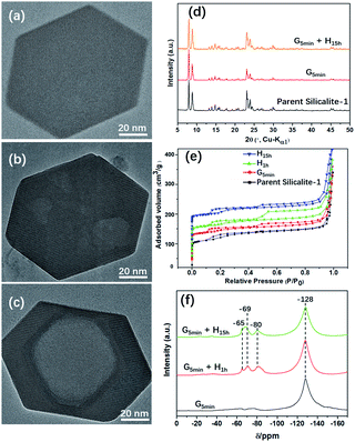
Fig. 1 shows TEM images of Silicalite-1 at different stages of mechanochemical grinding. It is noteworthy that multiple mesopores (5–30 nm) can be already generated after grinding only for 5 min at room temperature. During the following heating process, these irregular multiple mesopores start to merge and gradually grow larger and more regular, and eventually become a single macropore, which is similar to an inverse resemblance of the parent Silicalite-1 zeolite. The almost identical morphology and particle size between the post-treated samples and the parent Silicalite-1 suggest that the generation of these secondary pores involves no recrystallization process on the exterior surface (Fig. 1). This is also supported by the occasional presence of amorphous silica solids (Fig. S3†). We noticed that similar hollow structures can also be generated in Silicalite-1 by using TPAOH solution under hydrothermal conditions through a “dissolution–recrystallization” process,26 where the size of Silicalite-1 becomes larger due to the accumulation of recrystallized SiO2 species on the zeolite shell.27,28 Additionally, the post-treated Silicalite-1 possesses similarly high crystallinity as the parent Silicalite-1 and the MFI framework type retains, as shown by the powder XRD patterns in Fig. 1d and TEM results in Fig. S4.†The effects of experimental conditions, such as the mixture composition and the heating temperature, were also studied (Fig. S3 and S5†). Of note, a too high-temperature heating would cause a surface fusion of the zeolites, suggesting an etching on both the inner and outer parts of Silicalite-1 zeolite (Fig. S6†). Furthermore, this method was also applied to commercial Silicalite-1 and ZSM-5 with different Si/Al ratios, in which meso/macropores were also obtained (Fig. S7†).
Fig. 1e shows the N2 adsorption/desorption isotherms of the parent and post-treated Silicalite-1 samples. All isotherms exhibit two hysteresis loops at low pressure zone (P/P0 ≈ 0.2) and high-pressure zone (P/P0 = 0.6–0.9), respectively. The first hysteresis loop is attributed to the presence of internal structural defects29 and the second to the presence of inter-crystal mesopores.30 The hysteresis loops at low pressure zone slightly increase after post-treatment, indicating the increase of internal structural defects. On the other hand, the hysteresis loops at high pressure zone first increase after mechanical grinding and heating for 1 h, but then decrease with further heating, which may be caused by the merging of mesopores into macropore. In addition, the micropore properties including BET surface area and micropore volume of the post-treated samples show slight decrease, while the external surface area and mesopore volume increase at first but decrease after prolonged heating for 15 h (Table 1).
| Sample | SBET (cm2 g−1) | Sext (cm2 g−1) | Vmic (cm3 g−1) | Vmes (cm3 g−1) |
|---|---|---|---|---|
| a SBET (specific surface area) was obtained by BET method. Sext (external surface area), Vmic (micropore volume) and Vmes (mesopore volume) was obtained by t-plot method of the desorption branch. | ||||
| Silicalite-1 | 434 | 28.0 | 0.18 | 0.04 |
| G5 min | 412 | 31.0 | 0.19 | 0.03 |
| G5 min + H1 h | 403 | 32.5 | 0.21 | 0.01 |
| G5 min + H15 h | 399 | 30.0 | 0.18 | 0.03 |
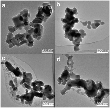
Of note, if there is no heating treatment, more mesopores would be formed at room temperature with the time, but would not merge into large macropores (Fig. 2a). On the other hand, upon heating the merging process takes places very rapidly (Fig. 2). This is a clear indication that the merging process is driven by the high temperature. Post-treated Silicalite-1 samples were analyzed by Powder XRD before washing (Fig. 3). After simple grinding, the diffraction peaks of TPABr are present while NH4F is absent in powder XRD profile, indicating that NH4F is completely consumed. This is also supported by the release of strong ammonium scent during the grinding process. Upon heating, the diffraction peaks of TPABr gradually disappear while the peaks of NH4Br start to emerge and intensify. On such basis, we propose the following chemical reactions:
| 6NH4F + SiO2 → (NH4)2SiF6 + 4NH3 + 2H2O | (1) |
| (NH4)2SiF6 + 2TPABr → (TPA)2SiF6 + 2NH4Br | (2) |
 | ||
| Fig. 2 TEM images of Silicalite-1 after grounded with TPABr–NH4F at (a) room temperature for 15 h, (b) 453 K for 1 h, (c) 453 K for 15 h, (d) 453 K for 48 h. | ||
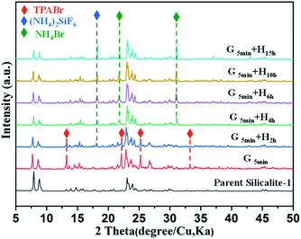 | ||
| Fig. 3 Powder XRD patterns of parent and unwashed post-treated Silicalite-1 zeolites under different conditions. G and H in (d–f) stand for grinding and heating treatment, respectively. | ||
It is noteworthy that NH4F is in excess amount to TPABr, so the majority of SiF62− species is still present as (NH4)2SiF6, which agrees well with the powder XRD results. Considering the SEM and XRD results mentioned above, it is concluded that the reaction (2) is the cause of the merging of multiple mesopores to macropore. On the other hand, powder XRD profiles of washed samples show only diffraction peaks of MFI-type zeolite, and these post-treated samples maintain the high crystallinity as the parent Silicalite-1 (Fig. 1d). The reaction (1) was also mentioned in the solvent-free synthesis of zeolites as the starting reactions,31 confirming the similarity of the fundamental mechanism between crystallization and dissolution of zeolites. However, transformation from TPABr to NH4Br was not detected in the solvent-free crystallization.31,32 This is probably because in crystallization process the TPA+ is pre-surrounded by silica precursor; while in dissolution process TPA+ is kept outside the framework due to diffusion limit rather than being surrounded by zeolitic framework as a template.
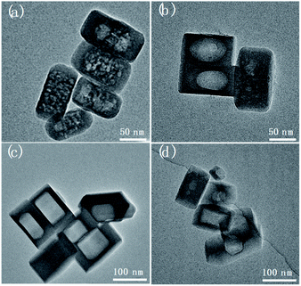
Qin has demonstrated the strong etching effect of NH4F solution to form cleavages and hollow mosaic structures inside MFI zeolites,22 but when NH4F was used alone in solvent-free condition, dissolution only happens on the surface even at elevated temperatures, with the resultant zeolite becoming roughly rounded or even “melted” to merge with each other (Fig. 4). On the other hand, the sole use of TPABr seems to have no effect on the zeolite, since no meso-/macropores are formed and no obvious morphological change can be observed in the Silicalite-1 (Fig. S8†). However, the rapid generation of mesoporosity by the combined use of TPABr–NH4F in solvent-free mechanochemical approach suggests that F− was effectively delivered into the zeolite framework. It should be noted although liquid water was not intentionally added, the presence of trace amount of water is inevitable in the system due to the hydroscopic nature of NH4F and TPABr.24,33 Moreover, the reaction between NH4F and SiO2 also releases water in the system as shown in eqn (1). The stoichiometric amount of water creates a local aqueous environment within the Silicalite-1. Under such environment NH4F readily diffuses into some structural defect zones such as intergrowth interfaces and/or grain boundaries which are more vulnerable to chemical attack by NH4F,22 and preferentially etches them to form multiple mesopores. At elevated temperatures, F− becomes more reactive, and therefore dissolution tends to inter-connect the multiple mesopores after the complete dissolution of defective zones. The further dissolution will undergo the inverse fashion of the layer-by-layer SiO2 accumulation during crystallization,26 that is, a layer-by-layer etching on certain lattice planes, to form the single macropore with well-defined edges and facets.
The state of fluoride species was monitored by 19F MAS NMR spectra of the post-treated Silicalite-1 samples (Fig. 1f). A remarkable band at −128 ppm was observed corresponding to the significant presence of (NH4)2SiF6.34 Upon heating, three new bands gradually emerge at −65, −69 and −80 ppm, respectively. The first signal is attributed to F− trapped in the [415262] cage of Silicalite-1, the second signal probably to ionically bonded TPA+–F− pair34 and the third signal to the presence of F− bonded to the structural defect.35 19F MAS NMR investigation on the solvent-free synthesis of zeolite discovers the simultaneous decrease of SiF62− and increase of F−, indicating a mass transformation from SiF62− to F− via the templating process of TPA+31−32. However, no such transformation were detected in the present study, which further confirms the non-templating effect of TPABr in generating the secondary pores.
Although not acting as a template, TPA+ plays an essential role in forming secondary porosity in Silicalite-1. To gain deeper understanding of the effect of TPA+ during solvent-free post-treatment, tetramethylammonium bromide (TMABr), tetraethylammonium bromide (TEABr) and cetyltrimethylammonium bromide (CTABr) with increasing ionic radius were also attempted (Fig. 5). It should be mentioned that only TMA+ is small enough (∼0.44 nm) to diffuse into the micropores of Silicalite-1 (∼0.57 nm), while TEA+, TPA+ and CTA+ are too bulky to enter the micropores.36,37 The results show that the secondary porosities of similar shape and size are also observed by using TEA+ and CTA+ but not by TMA+ (which shows only a slightly melted morphology). The inability of TMA+ to generate secondary pores is probably due to its easy diffusion into the channels, which renders surface vulnerable to F− attack while the pore is blocked by TMA+ and less accessible to F−. It is also noteworthy that TEA+ and CTA+ has no structure-directing effect towards MFI zeolites, so the formation of secondary mesopores is not a recrystallization process but a preferred dissolution. Compared with TPABr-treated Silicalite-1, the TEABr-treated Silicalite-1 shows smaller, multiple macropores after the same heating treatment, while CTABr-treated Silicalite-1 shows remarkably lager macropores. Such features can be reasonably attributed to, compared with TPABr, the weaker ability of TEABr and stronger ability of CTABr to shield the surface and to keep the micropore open for F− diffusion. On such basis, the unique dissolution process in the solvent-free environment was proposed to proceed in following steps: (i) the initial reaction between NH4F and silica framework forms a surficial layer of silanol anion Si–O−, which then adsorb bulky organic cations like TPA+ and prevent further etching on the surface. (ii) The presence of stoichiometric amount of water forms a local aqueous environment, delivering F− into the zeolite and selectively etch the defective zones.
Fig. 6 shows the elemental distribution map of the unwashed post-treated samples. The map of carbon shows a very thin enriched layer in the peripheral part of the Silicalite-1, confirming that TPA+ are preferentially adsorbed on the outer surface of zeolite. The fluoride distribution, however, is quite similar with silicon distribution, confirming the free diffusion of F− into the silica framework of zeolite. After thorough washing, a large amount of TPA+ and F− that are physically adsorbed on the outer surface are removed, as evidenced by the less intense carbon and fluoride signals on the outer part of zeolite. Nevertheless, the enriched carbon distribution in the peripheral part is still present for post-treated Silicalite-1, attributed to TPA+ bonded to surface Si–O− of zeolites; while a relatively uniform fluoride distribution is present across the whole framework domain. The above observation supports our proposal that TPA+ are kept on the surface while F− freely diffuses into the zeolite framework.
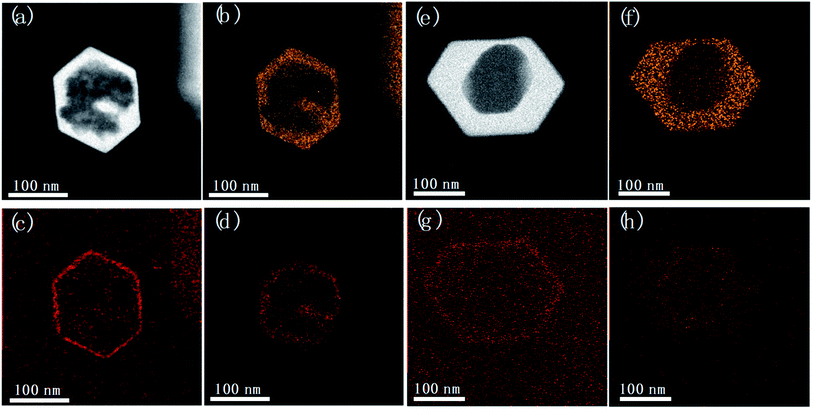 | ||
| Fig. 6 STEM images and EDS maps of (a–d) unwashed and (e–h) washed samples by post-treatment. Silicon (b and f), carbon (c and g) and fluoride (d and h) distribution map were separately displayed. | ||
Hierarchical zeolites can serve as the support to disperse38 or entrap39 active metal nanoparticles for specific catalytic applications. Especially, the encapsulation of noble and transition metal nanoparticles into hollow zeolites as core–shell or yolk–shell composites have been extensively studied for their great potential in catalytic applications.26,40 The metal nanoparticles encapsulated in such composite materials are expected to have high mono-dispersion of active sites that are strongly resistant against sintering at catalytic conditions.
Herein this solvent-free post-treatment was attempted to encapsulate platinum and cobalt nanoparticles, respectively.41–44 The loading of metal species was achieved by an impregnation method with the corresponding aqueous solution of precursor. TEM images were taken from the post-treated samples before calcination-reduction (Fig. S9†) and after calcination-reduction (Fig. 7). The results show that after grinding-heating treatment, the metal species were already transformed to nanoparticles (<10 nm) uniformly dispersed inside and outside Silicalite-1. After subsequent calcination-reduction process, larger nanoparticles emerge inside the meso-/macropores (Pt@Silicalite-1) or along the edges of meso-/macropores (Co@Silicalite-1), as well as on the outer surface (readily been washed out later). We propose the following hypothesis: firstly the metal salts are dissolved in the solution; during the impregnation, they adhere to the outer surface and enter the channels of the zeolites; as the F−-motivated dissolution proceeds, the metal species dissolved in trace amount of water diffuse with F− into the framework of Silicalite-1 and preferentially reside around the etched zones. During the heating treatment at 180 °C, these metal species convert to nanoparticles that are either sparsely dispersed around the meso-/macropores (Pt@Silicalite-1) or located on the edges of the meso-macropores (Co@Silicalite-1). The different morphologies of Pt and Co nanoparticles seem to be caused by the nature of Pt and Co elements, as similar results have been reported for Pt@Silicalite-1 and Co@Silicalite-1 zeolites prepared with the conventional hydrothermal post-treatment.13,45
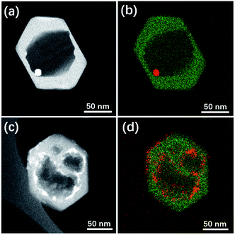 | ||
| Fig. 7 STEM images and EDS maps of (a and b) Pt@Silicalite-1 and (c and d) Co-Silicalite-1 samples. Note that in EDS map green colour stands for Si while red for Pt or Co. | ||
Upon high-temperature reduction, the nanoparticles are prone to assemble and grow larger. In the case of Pt–Silicalite-1, Pt nanoparticles diffuse into meso-/macropores to agglomerate into larger particles; while in the case of Co@Silicalite-1, the Co species agglomerate along the edges of secondary pores. The encapsulation of Pt and Co nanoparticles is further supported by the STEM-EDS results and TEM results of tilted samples (Fig. 7b, d and S10†). It is noteworthy that the absence of the water in the solvent-free route can effectively improve the utilization of metal precursors.
Conclusions
In summary, introduction of meso-/macropores in Silicalite-1 zeolite has been realized by a solvent-free mechanochemical reactions. The strategy allows the preservation of high crystallinity and microporosity of the pristine zeolite, and the generation of meso-/macropores. Study on the mass transfer in such solvent-free environment reveals a three-step process: (i) NH4F first reacts with surface of the zeolite, resulting in surface defects and stoichiometric amount of water; (ii) TPA+ ions are bonded with the surface to form a protective shield to keep F− from further reaction with outer surface; (iii) the local aqueous environment facilitates the free diffusion of F− into zeolite framework to selectively etch the zones with structural defects to form the secondary pores. The dissolution first occurs at structure defective zones to form multiple mesopores, and then inter-connects the mesopores and forms macropores via a layer-by-layer fashion on the crystal planes of Silicalite-1. The method also proves successful to encapsulate Pt and Co nanoparticle within the secondary pores, forming a single-Pt or multi-Co nanoparticle encapsulated yolk–shell zeolite composites.Conflicts of interest
There are no conflicts to declare.Acknowledgements
This work was supported by the National Natural Science Foundation of China (Grant 21835002 and 21875140). The authors thank Prof. Osamu Terasaki, CħEM SPST (Grant 02161943) and the support from Analytical Instrumentation Center (#SPST-AIC10112914), SPST, ShanghaiTech University for scientific and facilities supports.Notes and references
- T. C. Keller, E. G. Rodrigues and J. Pérez-Ramírez, Generation of Basic Centers in High-Silica Zeolites and their Application in Gas-Phase Upgrading of Bio-Oil, ChemSusChem, 2014, 7(6), 1729–1738 CrossRef CAS PubMed.
- J. M. Thomas, R. Raja, G. Sankar and R. G. Bell, Molecular-sieve catalysts for the selective oxidation of linear alkanes by molecular oxygen, Nature, 1999, 398(6724), 227–230 CrossRef CAS.
- S. Saravanamurugan, M. Paniagua, J. A. Melero and A. Riisager, Efficient isomerization of glucose to fructose over zeolites in consecutive reactions in alcohol and aqueous media, J. Am. Chem. Soc., 2013, 135(14), 5246–5249 CrossRef CAS PubMed.
- N. Wang, Q. Sun, R. Bai, X. Li, G. Guo and J. Yu, In Situ Confinement of Ultrasmall Pd Clusters within Nanosized Silicalite-1 Zeolite for Highly Efficient Catalysis of Hydrogen Generation, J. Am. Chem. Soc., 2016, 138(24), 7484–7487 CrossRef CAS PubMed.
- C. Xia, M. Lin, A. Zheng, Y. Xiang, B. Zhu, G. Xu and X. Shu, Irreversible deactivation of hollow TS-1 zeolite caused by the formation of acidic amorphous TiO2–SiO2 nanoparticles in a commercial cyclohexanone ammoximation process, J. Catal., 2016, 338, 340–348 CrossRef CAS.
- J. Wang, J. Li, S. Xu, Y. Zhi, Y. Wei, Y. He, J. Chen, M. Zhang, Q. Wang, W. Zhang, X. Wu, X. Guo and Z. Liu, Methanol to hydrocarbons reaction over HZSM-22 and SAPO-11: Effect of catalyst acid strength on reaction and deactivation mechanism, Chin. J. Catal., 2015, 36(8), 1392–1402 CrossRef CAS.
- W. Schwieger, A. G. Machoke, T. Weissenberger, A. Inayat, T. Selvam, M. Klumpp and A. Inayat, Hierarchy concepts: classification and preparation strategies for zeolite containing materials with hierarchical porosity, Chem. Soc. Rev., 2016, 45(12), 3353–3376 RSC.
- D. Verboekend, N. Nuttens, R. Locus, J. Van Aelst, P. Verolme, J. C. Groen, J. Pérez-Ramírez and B. F. Sels, Synthesis, characterisation, and catalytic evaluation of hierarchical faujasite zeolites: milestones, challenges, and future directions, Chem. Soc. Rev., 2016, 45(12), 3331–3352 RSC.
- Q. Zhang, A. Mayoral, O. Terasaki, Q. Zhang, B. Ma, C. Zhao, G. Yang and J. Yu, Amino Acid-Assisted Construction of Single-Crystalline Hierarchical Nanozeolites via Oriented-Aggregation and Intraparticle Ripening, J. Am. Chem. Soc., 2019, 141(9), 3772–3776 CrossRef CAS.
- Z. Qin, B. Shen, Z. Yu, F. Deng, L. Zhao, S. Zhou, D. Yuan, X. Gao, B. Wang, H. Zhao and H. Liu, A defect-based strategy for the preparation of mesoporous zeolite Y for high-performance catalytic cracking, J. Catal., 2013, 298, 102–111 CrossRef CAS.
- J. C. Groen, T. Bach, U. Ziese, A. M. Paulaime-van Donk, K. P. de Jong, J. A. Moulijn and J. Pérez-Ramírez, Creation of Hollow Zeolite Architectures by Controlled Desilication of Al-Zoned ZSM-5 Crystals, J. Am. Chem. Soc., 2005, 127(31), 10792–10793 CrossRef CAS PubMed.
- C. Pagis, A. R. Morgado Prates, D. Farrusseng, N. Bats and A. Tuel, Hollow Zeolite Structures: An Overview of Synthesis Methods, Chem. Mater., 2016, 28(15), 5205–5223 CrossRef CAS.
- S. Li, A. Tuel, D. Laprune, F. Meunier and D. Farrusseng, Transition-Metal Nanoparticles in Hollow Zeolite Single Crystals as Bifunctional and Size-Selective Hydrogenation Catalysts, Chem. Mater., 2015, 27(1), 276–282 CrossRef CAS.
- Z. Qin, K. A. Cychosz, G. Melinte, H. El Siblani, J.-P. Gilson, M. Thommes, C. Fernandez, S. Mintova, O. Ersen and V. Valtchev, Opening the Cages of Faujasite-Type Zeolite, J. Am. Chem. Soc., 2017, 139(48), 17273–17276 CrossRef CAS PubMed.
- Z. Qin, L. Lakiss, J. P. Gilson, K. Thomas, J. M. Goupil, C. Fernandez and V. Valtchev, Chemical Equilibrium Controlled Etching of MFI-Type Zeolite and Its Influence on Zeolite Structure, Acidity, and Catalytic Activity, Chem. Mater., 2013, 25(14), 2759–2766 CrossRef CAS.
- S. Yang, C. Yu, L. Yu, S. Miao, M. Zou, C. Jin, D. Zhang, L. Xu and S. Huang, Bridging Dealumination and Desilication for the Synthesis of Hierarchical MFI Zeolites, Angew. Chem., Int. Ed., 2017, 56(41), 12553–12556 CrossRef CAS PubMed.
- Y. Qiao, M. Yang, B. Gao, L. Wang, P. Tian, S. Xu and Z. Liu, Creation of hollow SAPO-34 single crystals via alkaline or acid etching, Chem. Commun., 2016, 52(33), 5718–5721 RSC.
- X. D. Wang, W. L. Yang, Y. Tang, Y. J. Wang, S. K. Fu and Z. Gao, Fabrication of hollow zeolite spheres, Chem. Commun., 2000, 21, 2161–2162 RSC.
- P. M. Arnal, C. Massimiliano and S. Ferdi, High-Temperature-Stable Catalysts by Hollow Sphere Encapsulation, Angew. Chem., Int. Ed., 2006, 45(48), 8224–8227 CrossRef CAS PubMed.
- D. Verboekend, G. Vilé and J. Pérez-Ramírez, Hierarchical Y and USY Zeolites Designed by Post-Synthetic Strategies, Adv. Funct. Mater., 2012, 22(5), 916–928 CrossRef CAS.
- Y. Wang, M. Lin and A. Tuel, Hollow TS-1 crystals formed via a dissolution–recrystallization process, Microporous Mesoporous Mater., 2007, 102(1), 80–85 CrossRef CAS.
- Z. Qin, G. Melinte, J.-P. Gilson, M. Jaber, K. Bozhilov, P. Boullay, S. Mintova, O. Ersen and V. Valtchev, The Mosaic Structure of Zeolite Crystals, Angew. Chem., Int. Ed., 2016, 55(48), 15049–15052 CrossRef CAS PubMed.
- Q. W. Wang, Y. J. Mu, W. L. Zhang, L. S. Zhong, Y. Meng and Y. H. Sun, A facile solvent-free route to synthesize ordered mesoporous carbons, RSC Adv., 2014, 4(61), 32113–32116 RSC.
- Y. Y. Jin, Q. Sun, G. D. Qi, C. G. Yang, J. Xu, F. Chen, X. J. Meng, F. Deng and F. S. Xiao, Solvent-Free Synthesis of Silicoaluminophosphate Zeolites, Angew. Chem., Int. Ed., 2013, 52(35), 9172–9175 CrossRef CAS PubMed.
- L. Ren, Q. Wu, C. Yang, L. Zhu, C. Li, P. Zhang, H. Zhang, X. Meng and F.-S. Xiao, Solvent-Free Synthesis of Zeolites from Solid Raw Materials, J. Am. Chem. Soc., 2012, 134(37), 15173–15176 CrossRef CAS PubMed.
- D. Chengyi, Z. Anfeng, L. Min, G. Xinwen and S. Chunshan, Hollow ZSM-5 with Silicon-Rich Surface, Double Shells, and Functionalized Interior with Metallic Nanoparticles and Carbon Nanotubes, Adv. Funct. Mater., 2015, 25(48), 7479–7487 CrossRef.
- D. Laprune, A. Tuel, D. Farrusseng and F. C. Meunier, Highly Dispersed Nickel Particles Encapsulated in Multi-hollow Silicalite-1 Single Crystal Nanoboxes: Effects of Siliceous Deposits and Phosphorous Species on the Catalytic Performances, ChemCatChem, 2017, 9(12), 2297–2307 CrossRef CAS.
- C. Dai, A. Zhang, L. Li, K. Hou, F. Ding, J. Li, D. Mu, C. Song, M. Liu and X. Guo, Synthesis of Hollow Nanocubes and Macroporous Monoliths of Silicalite-1 by Alkaline Treatment, Chem. Mater., 2013, 25(21), 4197–4205 CrossRef CAS.
- A. M. Silvestre-Albero, J. M. Juárez-Galán, J. Silvestre-Albero and F. Rodríguez-Reinoso, Low-Pressure Hysteresis in Adsorption: An Artifact?, J. Phys. Chem. C, 2012, 116(31), 16652–16655 CrossRef CAS.
- A. Azhati, S. Xie, W. Wang, A. A. Elzatahry, Y. Yan, J. Zhou, D. Al-Dhayan, Y. Zhang, Y. Tang and D. Zhao, Ordered, Highly Zeolitized Mesoporous Aluminosilicates Produced by a Gradient Acidic Assembly Growth Strategy in a Mixed Template System, Chem. Mater., 2016, 28(13), 4859–4866 CrossRef CAS.
- Q. Wu, X. Liu, L. Zhu, L. Ding, P. Gao, X. Wang, S. Pan, C. Bian, X. Meng, J. Xu, F. Deng, S. Maurer, U. Muller and F.-S. Xiao, Solvent-Free Synthesis of Zeolites from Anhydrous Starting Raw Solids, J. Am. Chem. Soc., 2015, 137(3), 1052–1055 CrossRef CAS PubMed.
- Q. M. Wu, X. J. Meng, X. H. Gao and F. S. Xiao, Solvent-Free Synthesis of Zeolites: Mechanism and Utility, Acc. Chem. Res., 2018, 51(6), 1396–1403 CrossRef CAS PubMed.
- N. Sheng, Y. Chu, S. Xin, Q. Wang, X. Yi, Z. Feng, X. Meng, X. Liu, F. Deng and F.-S. Xiao, Insights of the Crystallization Process of Molecular Sieve AlPO4-5 Prepared by Solvent-Free Synthesis, J. Am. Chem. Soc., 2016, 138(19), 6171–6176 CrossRef CAS PubMed.
- L. Delmotte, M. Soulard, F. Guth, A. Seive, A. Lopez and J. L. Guth, 19F MAS n.m.r. studies of crystalline microporous solids synthesized in the fluoride medium, Zeolites, 1990, 10(8), 778–783 CrossRef CAS.
- L. Zhang, Y. Song, G. Li, Q. Zhang, S. Zhang, J. Xu, F. Deng and Y. Gong, F-assisted synthesis of a hierarchical ZSM-5 zeolite for methanol to propylene reaction: a b-oriented thinner dimensional morphology, RSC Adv., 2015, 5(75), 61354–61363 RSC.
- J. Pérez-Ramírez, D. Verboekend, A. Bonilla and S. Abelló, Zeolite Catalysts with Tunable Hierarchy Factor by Pore-Growth Moderators, Adv. Funct. Mater., 2009, 19(24), 3972–3979 CrossRef.
- J. García-Martínez, M. Johnson, J. Valla, K. Li and J. Y. Ying, Mesostructured zeolite Y—high hydrothermal stability and superior FCC catalytic performance, Catal. Sci. Technol., 2012, 2(5), 987–994 RSC.
- J. Kang, K. Cheng, L. Zhang, Q. Zhang, J. Ding, W. Hua, Y. Lou, Q. Zhai and Y. Wang, Mesoporous Zeolite-Supported Ruthenium Nanoparticles as Highly Selective Fischer–Tropsch Catalysts for the Production of C5–C11 Isoparaffins, Angew. Chem., 2011, 123(22), 5306–5309 CrossRef.
- J. Gu, Z. Zhang, P. Hu, L. Ding, N. Xue, L. Peng, X. Guo, M. Lin and W. Ding, Platinum Nanoparticles Encapsulated in MFI Zeolite Crystals by a Two-Step Dry Gel Conversion Method as a Highly Selective Hydrogenation Catalyst, ACS Catal., 2015, 5(11), 6893–6901 CrossRef CAS.
- S. Li, A. Tuel, F. Meunier, M. Aouine and D. Farrusseng, Platinum nanoparticles entrapped in zeolite nanoshells as active and sintering-resistant arene hydrogenation catalysts, J. Catal., 2015, 332(Supplement C), 25–30 CrossRef CAS.
- T. C. Keller, S. Isabettini, D. Verboekend, E. G. Rodrigues and J. Perez-Ramirez, Hierarchical high-silica zeolites as superior base catalysts, Chem. Sci., 2014, 5(2), 677–684 RSC.
- T.-L. Cui, W.-Y. Ke, W.-B. Zhang, H.-H. Wang, X.-H. Li and J.-S. Chen, Encapsulating Palladium Nanoparticles Inside Mesoporous MFI Zeolite Nanocrystals for Shape-Selective Catalysis, Angew. Chem., Int. Ed., 2016, 55(32), 9178–9182 CrossRef CAS PubMed.
- Z. Wu, S. Goel, M. Choi and E. Iglesia, Hydrothermal synthesis of LTA-encapsulated metal clusters and consequences for catalyst stability, reactivity, and selectivity, J. Catal., 2014, 311, 458–468 CrossRef CAS.
- S. Goel, S. I. Zones and E. Iglesia, Encapsulation of Metal Clusters within MFI via Interzeolite Transformations and Direct Hydrothermal Syntheses and Catalytic Consequences of Their Confinement, J. Am. Chem. Soc., 2014, 136(43), 15280–15290 CrossRef CAS PubMed.
- S. Li, T. Boucheron, A. Tuel, D. Farrusseng and F. Meunier, Size-selective hydrogenation at the subnanometer scale over platinum nanoparticles encapsulated in silicalite-1 single crystal hollow shells, Chem. Commun., 2014, 50(15), 1824–1826 RSC.
Footnote |
| † Electronic supplementary information (ESI) available. See DOI: 10.1039/d0ra00670j |
| This journal is © The Royal Society of Chemistry 2020 |

