 Open Access Article
Fabrication of fibrillated and interconnected porous poly(ε-caprolactone) vascular tissue engineering scaffolds by microcellular foaming and polymer leaching†
Jianhua Houa,
Jing Jiang *ab,
Haiyang Guoa,
Xin Guoa,
Xiaofeng Wang
 a,
Yaqiang Shenc and
Qian Li*a
aSchool of Mechanics & Engineering Science, Zhengzhou University, National Center for International Joint Research of Micro-Nano Molding Technology, Zhengzhou, 450001, PR China. E-mail: qianli@zzu.edu.cn
bSchool of Mechanical Engineering, Zhengzhou University, Zhengzhou, 450001, PR China. E-mail: jiangjing@zzu.edu.cn
cShenzhen ZhaoWei Machinery & Electronics Co.,Ltd., Shenzhen, 518000, PR China
First published on 10th March 2020
Abstract
This paper provides a method combining eco-friendly supercritical CO2 microcellular foaming and polymer leaching to fabricate small-diameter vascular tissue engineering scaffolds. The relationship between pore morphology and mechanical properties, and the cytocompatibility, are investigated with respect to the effects of poly(ε-caprolactone)/poly(ethylene oxide) (PCL/PEO) phase morphologies and PEO leaching. When PEO content increases, the pore size decreases and the pore density increases. After the leaching process, highly interconnected and fibrillated porous structures are detected in the foamed PCL70 blend with droplet-matrix morphologies. Moreover, the leaching process had a greater contribution to improve the open-cell content in the PCL50 blend, which has a co-continuous morphology and easily obtained open-cell content of more than 80%. Small-diameter tubular PCL70 and PCL50 porous scaffolds with an average pore size of 48 ± 1.4 μm and 30 ± 1.0 μm respectively, are fabricated successfully. Prominent orientated pores are found in the PCL70 scaffold, and a mixed microstructure combining interconnected channels and open cells occurs in PCL50 scaffold. The PCL70 scaffold has a greater longitudinal tensile strength, longer toe region, and larger cyclical recoverability. HUVECs tend to align along the direction of the pore orientation in the PCL70 scaffold, whereas HUVECs have a higher density and spreading area in the PCL50 scaffold. The results gathered in this paper may provide a theoretical basis and data support for fabricating small-diameter porous tissue engineering vascular scaffolds.
1. Introduction
In recent years, tissue engineering, as a new treatment, has been used to improve the recovery of various types of tissue, such as bones, blood vessels, the oesophagus and skin.1,2 The application of vascular tissue engineering technology holds great promise for improving outcomes in patients with peripheral vascular diseases and cardiac ischemia.3 Although some progress has been achieved in developing vascular grafts using materials such as expanded polytetrafluorethylene (e-PTFE), generating vascular grafts with a small diameter (≤6 mm) is still challenging due to the risk of infection, thrombus, and calcification when implanted.4 Therefore, the development of new scaffolds with a smaller vasculature diameter is imperative for the advancement of vascular tissue engineering.As one of the most important elements of tissue engineering, the scaffold acts as a synthetic analogue of the natural extracellular matrix (ECM). To meet tissue engineering requirements, the physical topology of the scaffold should be a three-dimensional (3D), highly porous structure with interconnected channels and hierarchical in pore size.5 A highly porous and interconnected 3D structure will not only facilitate cell adhesion, migration, and reproduction into the interior part of the scaffold, but also can support the mass transport of cell nutrients and waste.6 In fact, it is not easy to produce such high-porosity scaffolds with specified geometric shapes and the necessary mechanical properties. Being hierarchical in pore size refers to the various scales and their effects; for example, mesoscopic pores (>50 μm) influence tissue shape, microscopic pores (1–50 μm) influence cell function, and nanoscopic pores (<1 μm) influence nutrient diffusion.7 Therefore, how to produce a scaffold with pores that are highly open, interconnected, and a desirable size and have a uniform distribution is the key point of scaffold fabrication in tissue engineering.
Until now, several different techniques (e.g., solvent extraction, particle leaching, phase separation, electrospinning, rapid prototyping, and gas foaming8–12) have been established based on biodegradable polymers to fabricate the ideal scaffold structure. Gas foaming is attracting more and more interest from researchers because of its advantages of being free of organic solvents and eco-friendly.13,14 During this process, carbon dioxide (CO2), which is as widely used as it is inexpensive, non-toxic, highly dissolvable in polymers, recoverable, and reusable, is first dissolved into a polymer melt at a certain temperature and pressure. After the CO2 turns to a supercritical fluid (SCF), it is depressurised to ambient levels to trigger the nucleation. A porous structure then emerges due to the expansion of the CO2 when it transitions from the supercritical to the gaseous state. However, this process is limited by the variety of pore size it can create, as well as their uncontrollable shape. In most cases, low interconnectivity results because that the gas expansion force is too small to overcome the strength of the polymer matrix.15 Particle leaching is an effective technique for producing fully interconnected porous scaffolds. This technique blends water-soluble inorganic particles or polymers with one matrix material; a porous structure can be generated after leaching the sacrificial phase. The disadvantages of unpredictable pore sizes and poor mechanical properties have been detected during scaffold fabrication by a single particle leaching process. To further improve the porosity and interconnectivity of the scaffold, a scaffold fabrication method combining gas foaming and polymer leaching can be used and is attracting increased attention.16,17 This mixed method can give scaffolds that perform better than those of a given individual process in tissue engineering applications.
Many synthetic thermoplastic aliphatic polymers, such as polylactide (PLA), polyglycolide (PGA), poly(ε-caprolactone) (PCL), and poly(lactide-co-glycolide) (PLGA), have been commonly used to fabricate tissue engineering scaffolds because of their excellent biodegradability and biocompatibility.18–20 PCL, a semi-crystalline polymer, has been a popular biomedical material for tissue engineering. PCL has good mechanical properties such as high flexibility and elongation. The degradation time of PCL can reach up to 24 months by hydrolytic scission.21,22 Most PCL scaffolds are fabricated by electrospinning. Poly(ethylene oxide) (PEO) is another biomedical polymer that is biodegradable, biocompatible, and water-soluble. PEO itself is non-toxic to cells and can be dissolved without toxic organic solvents. Therefore, any residual polymer will not affect the cell viability23
This study prepares a highly interconnected, biocompatible and biodegradable, porous, tubular PCL scaffold with finely controlled porous microstructures. A solid-state supercritical CO2 batch foaming process and a polymer leaching method are combined. The effects of the blend composition and phase morphology on the foaming behaviour and final pore morphology, as well as the polymer leaching efficiency, are investigated. Pore size, pore density, and open-cell content are measured quantitatively. Furthermore, tubular PCL scaffolds with a desired pore size and highly interconnected porous structures are fabricated successfully. Related tensile properties and cytocompatibility are explored.
2. Materials and methods
2.1 Materials
PCL (CAPA 6500, Perstorp) was used as the matrix material. PEO (WSR N-10, Dow) was chosen as the sacrificial material due to its water solubility and similarity in melt temperature to that of PCL. Some characteristics of PCL and PEO are listed in Table 1. The PCL and PEO were stored in sealed containers to minimize moisture absorption and were further dried at 40 °C under vacuum for 24 h prior to compounding.| Material | Mn × 10−3 (g mol−1) | Tg (°C) | Tm (°C) | Melt flow index (g/10 min) | Density at 23 °C (g cm−3) |
|---|---|---|---|---|---|
| PCL | 50 | −60 | 58 | 7 | 1.14 |
| PEO | 100 | −70 | 63 | — | 1.21 |
2.2 Fabrication of porous PCL scaffold
The compounding of PCL and PEO was carried out on a 20 mm twin-screw extruder (TSE-20) operating at 100 °C (the die temperature) at a rotation speed of 150 rpm, followed by cooling and granulation. Different polymer blends with a variety of mass formulas were prepared-solid PCL (neat PCL), 80% PCL/20% PEO (PCL80), 70% PCL/30% PEO (PCL70), 60% PCL/40% PEO (PCL60), and 50% PCL/50% PEO (PCL50).The pre-blended pellets were hot embossed into thin membranes with a thickness of 200 ± 10 μm. Rectangular films (20 mm × 15 mm) were cut from the middle regions. A tubular mould was specially designed with an inner diameter (ID) of 5 mm, and assembled with one metal core with an outer diameter (OD) of 4 mm. One layer of aluminium-foil paper was stuck onto the inner mould wall to help with demoulding. Then, the film was inserted into the mould to form a tube. Next, tubular-shaped specimens (OD = 5 mm, ID = 4 mm) were placed into a high-pressure vessel made in-house that had been preheated to a saturation temperature (Tsat) for 1.5 h. The vessel was flushed with low-pressure CO2 for 2 min using a syringe pump and then filled with CO2 to the desired saturation pressure (Psat) and hold for the desired saturation time (tsat). The system, in which CO2 had transitioned into the SCF, was kept in equilibrium at Tsat, Psat and tsat to ensure full adsorption of CO2. The pressure was quenched to ambient pressure in a very short time (0.5–1 s), and the samples were quickly removed from the vessel. The saturation conditions for foaming were based on our previous research and were Tsat = 42 °C, Psat = 2000 psi, and tsat = 1 h. The resulting foamed PCL/PEO scaffolds were immersed into deionized water to leach out the PEO. The water was changed every 6 h until a constant weight was obtained. After that, the wet scaffolds were dried in vacuum oven at 37 °C for 24 h to remove any moisture. The whole process of preparing the porous PCL scaffolds was illustrated in Fig. 1.
2.3 Characterization and measurement
All samples were fractured at liquid nitrogen temperature. The SEM observations were made after sputtering the samples with a thin film of gold for 60 s at 2 mA.
The pore size and pore density were estimated by tracing a minimum of 100 pores from SEM micrographs using the Image-Pro Plus software, which enables one to assess the diameter of each pore. The average pore diameter (D) of all the pores in the SEM micrograph was calculated with eqn (1):24
 | (1) |
 | (2) |
 | (3) |
 | (4) |
 | (5) |
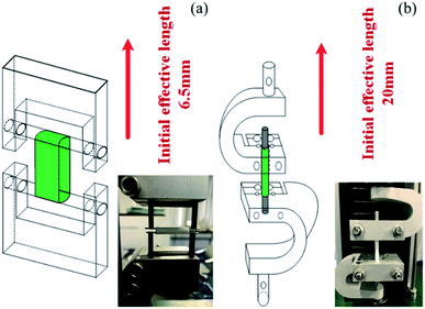
All tests were done on a computer-controlled SANS tester (Model UTM 2203) with a 100 N load cell. As shown in Fig. 2(a) and (b), the fixtures were specifically designed for tubular scaffolds. The effective initial lengths for the longitudinal and radial tensile testing were 20 mm and 6.5 mm, respectively. A pre-tension of 0.1 N was applied to all samples. The extension rate of 5 mm min−1 was used during the tensile test until the sample failed. The broken stress and strain of each sample was tested based on ISO 7198:1998. The modulus of the sample was defined as the slope of the stress–strain curve at 5% elongation. Statistical results were the average of four samples. To avoid the possible reduction of the foam volume, all characterizations were carried out after the foams were placed in the constant temperature and humidity chamber (23 ± 2 °C, relative humidity of 40–50%) for 3 days.
The cells were fixed with 4% formaldehyde for 10 min, penetrated with PBS containing 0.5% Triton X-100 for 10 min, then blocked with PBS containing 5% bovine serum albumin for 30 min, and washed with PBS three times. Cells were incubated with a phalloidin dilution (1/40 v/v dilution in PBS) overnight at 4 °C, nuclear DNA was labelled with a 4′,6-diamidino-2-phenylindole (DAPI) dilution (1/10 v/v dilution in PBS), and cells were imaged with a confocal laser scanning microscope.
3. Results and discussion
3.1 Morphology of PCL/PEO blend
SEM was first used to characterize the phase morphology of neat PCL and the PCL/PEO blends. The micrographs were used to further understand the components' compatibility. Fig. 3 shows SEM images of the fracture surface for neat PCL and PCL/PEO blends with various blend ratios after leaching. All samples exhibited typical binary structures, which further proved the immiscibility of PCL and PEO. Neat PCL (Fig. 3(a)) showed a relatively smooth fracture surface. Dispersed droplets of the minor phase in the matrix were observed with the addition of 20% and 30% PEO (Fig. 3(b) and (c)) , respectively, and the fractured surface became slightly rough. The average size of the dispersed PEO phase increased from 0.8 μm to 2 μm when PEO content increased by 10%. As the content of PEO phase increased to 40%, the morphology changed significantly. The dispersed phase clearly showed an elongated or fibrous structure (Fig. 3(d)) and a partially co-continuous morphology emerged. Average size of dispersed PEO increased to 6 μm. The number of voids increased and voids interconnected with each other as the amount of PEO increased up to 50%. Continuous channels were clearly seen and were more uniformly distributed throughout than in the samples with 40% PEO components (Fig. 3(e)). Channels on the void walls were visible, suggesting the formation of a fully co-continuous phase.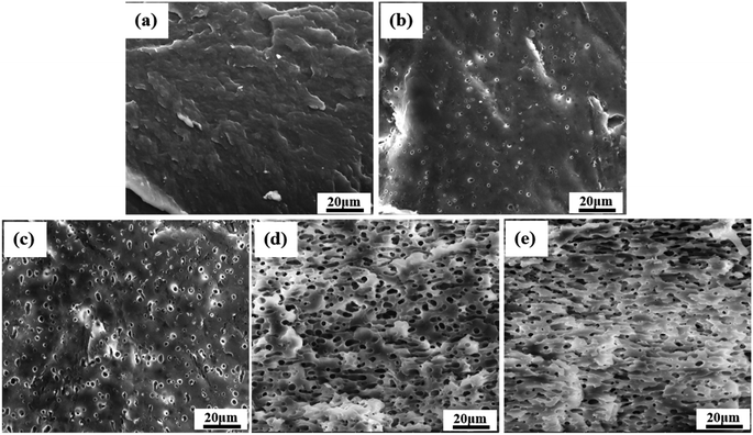 | ||
| Fig. 3 SEM micrographs, after leaching of PEO, of the fractured cross section of samples made with neat PCL and PCL/PEO blends: (a) neat PCL, (b) PCL80, (c) PCL70, (d) PCL60, and (e) PCL50. | ||
3.2 Rheological property
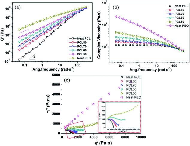
The foamability of polymeric material is strongly affected by its rheological behaviour.26,27 Fig. 4 shows the dynamic storage modulus (G′), complex viscosity (η*) and Cole–Cole curves obtained from rheological tests. A well-developed dependence was observed in that G′ decreased with an increase in PCL content at all frequencies tested. The modulus approached the terminal behaviour, G′–ω2, for neat PCL at low frequencies. A monotonic increase of G′ in the blends was found with increasing PEO content. However, the growth of G′ was not regular with the composition (as shown by the slightly different slopes of the dashed lines in Fig. 4(a)) when the PEO content was raised above 40 wt%. Such a rheological transition is due to the change of phase morphology during the oscillatory shear deformation.28 While in a high-frequency region, the energy level was negligible compared with the elastic energy level required for the deformation within the polymer blends. So, all samples approximately show a common G′. The complex viscosity is usually considered a reflection of melt strength. As shown in Fig. 4(b), an almost a typical Newtonian fluid behaviour was exhibited for the neat PCL. The phenomenon of shear-thinning increased greatly with an increase of PEO content, and the PEO exhibited typical pseudoplastic fluid behaviour. The viscosity of PCL/PEO blends fell between those of the PCL and PEO. It was efficient to improve the melt strength by adding PEO, which favoured the formation of open-pore structures. Fig. 4(c) shows the Cole–Cole plots of imaginary viscosity (η′′) versus real viscosity (η′) for all components. The homogeneous polymers exhibited only one circular arc in the curve, while a tail appeared on the right-hand side of the arc for all blends. An upward trend of the curve in high-viscosity region was observed for the blends PCL60 and PCL50, and a second circular-like arc was formed. Such plot behaviour demonstrated that there were two different relaxation mechanisms corresponding to the two different phase morphologies,29 in agreement with the SEM micrographs.3.3 Morphology of scaffolds before and after leaching PEO
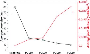
The effect of the PEO concentration on the morphology of the PCL foams before leaching PEO is shown in Fig. 5. Neat PCL exhibited a huge circular pore structure, and most of the pores had a closed-pore structure. As seen in the SEM micrographs Fig. 5(b)–(e), all pores were characterized by a sharply decreased size and an open-pore morphology. The shape of the pores changed from having regular polyhedral faces (Fig. 5(a)) to being a fully random polygon (Fig. 5(d) and (e)). Increasing the concentration of PEO from 20 wt% to 50 wt% increased the thickness of pores and decreased the number of well-interconnected pores. Fig. 5(d) shown that nonuniform pore distribution were found and many pores seems be “collapse”. That was may due to the phase morphology of PCL60 blend. We could see from the Fig. 3(d) that the dispersed PEO phase showed an elongated structure and a partially co-continuous morphology. The non-uniform dispersion of PEO phases lead to inhomogeneous nucleation during foaming. Non-uniform PEO phases combined with PCL made the pore wall more thicker. Various interface bonding between PEO and PCL made the pore wall collapse-like and unsmooth. When the PEO was increased to 50 wt%, more unfoamed regions were detected compared with PCL60 samples. Another feature exhibted from the morphologies of PCL/PEO foamed samples was non-homogeneous structures detected with a narrow pore size distribution because of the various foaming behaviors of PCL and PEO. To further characterise the pore structure, the average pore size and pore density were measured, as shown in Fig. 6. The plot shows that the average pore size decreased from 79.5 μm to 8.2 μm, while the average pore density increased from 1.5 × 10⁵ to 8.9 × 10⁸ cells per cm3, as the PEO content increased. These results occured because the heterogeneous nucleation effect was strengthened after PEO was added, which increased the number of nucleating points and restricted the expansion of cells.30,31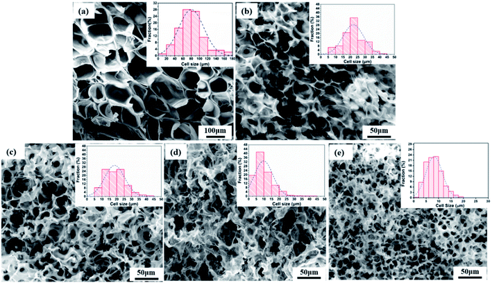 | ||
| Fig. 5 SEM images of foamed PCL/PEO samples before leaching PEO and their pore size distributions: (a) neat PCL, (b) PCL80, (c) PCL70, (d) PCL60, and (e) PCL50. | ||
Fig. 7 exhibits the morphology of foamed PCL/PEO samples after efficient leaching of the PEO (ESI Fig. S2†). All samples showed a highly interconnected pore structure with holes fractured in the pore walls. Fully random polygon pore shape were also found. The pores were interconnected with many fibrillated structures at the nano-scale for the PCL80, PCL70 and PCL60 foamed samples. This result could be explained from a phase morphology point of view. The matrix phase was PCL, which showed good strength in PCL80 and PCL70 blend systems, as shown by SEM. The pore walls of PCL were stretched to a certain extent during cell expansion. Under the function of CO2-induced plasticisation, the thickness of the pore walls decreased, and the walls resisted the dispersion of PEO with its higher melt strength. The matrix PCL became too weak to sustain cell expansion, and then the pores tended to break, which resulted in open pores and fibrillated structures among the pore walls. Such structures have been found in other research papers and were useful for enhancing cell adhesion during cell culturing.32,33 Many continuous channels appeared after leaching PEO for PCL50 samples. Multiple morphologies of open porous structures appeared. For the pre-leached PCL50 scaffolds, pore morphology characterized with small pore size and high pore density. Probably many PEO phases located on the pore walls. Even some pore walls were only made of PEO material. In that case, the continuous channels shown in Fig. 7(e) emerged after leaching process. Some channels came from the co-continuous PEO phase, and others were attributed to the connected PCL pores after the PEO on the pore walls were leached out. Such continuous channels combined with cell-opening PCL pores built a highly interconnected porous structure, which would probably enhance cell adhesion and migration during cell culturing.
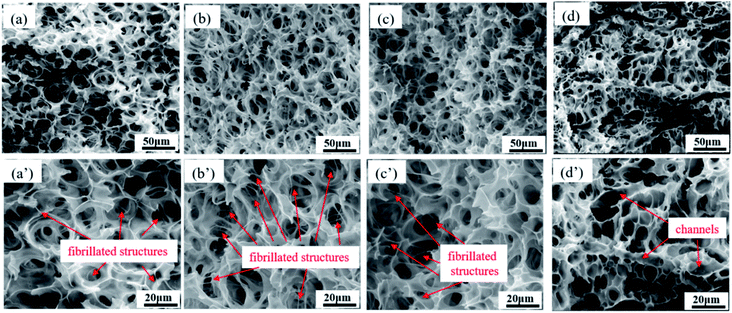 | ||
| Fig. 7 SEM images of foamed PCL/PEO samples after leaching PEO, showing their pore size distributions: (a) PCL80, (b) PCL70, (c) PCL60, and (d) PCL50; (a′) through (d′) are enlarged images. | ||
3.4 Overall porosity and interconnectivity of scaffolds
The statistical results of porosity are shown in Fig. 8(a). As expected, increasing the concentration of PEO induced an increase in overall porosity. The porosity increased from 67% to 88% with an increasing concentration of PEO from 0% to 30%. The porosity decreased slightly for the PCL60 foamed samples, which may be the fact that it was not possible to leach out the PEO phase. For the PCL50 foamed sample, the porosity can reach 89% because of leaching process. Fig. 8(b) depicted the open-pore content of PCL/PEO foamed samples before and after leaching. In contrast with the porosity, the open-pore content increased first and then decreased as the amount of PEO increased. Before leaching the PEO, a maximum open-pore content of 78% was obtained with PCL70. Because a co-continuous morphologies emerged when the concentration of PEO was more than 30%. The interface bonding force between PCL and PEO phases was too large to help cell nucleation and cell growth,34,35 so that it would be difficult to initiate the opening of a cell at the cell wall because of the higher melt strength. After the leaching process, the open-pore content was obviously improved for all the foamed samples, and the maximum porosity of 85% was detected with PCL70. Additionally, the average increment of open-pore content was about 5% after leaching for the PCL80 and PCL70. However, the average increment of open-pore content increased by 11% when the concentration of PEO added changed from 30% to 50%. This phenomenon indicated that the method of blending the immiscible polymers had a big effect on the interconnectivity of pores when the content of PEO was low. However, the leaching process contributed more to the open-pore content of the porous scaffolds after the co-continuous morphologies of the PCL/PEO blends emerged.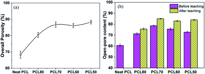 | ||
| Fig. 8 Comparison of the results for the porosity (a) and open-pore content (b) of the foamed PCL/PEO scaffolds. | ||
3.5 Morphology of small diameter porous PCL tubular scaffolds
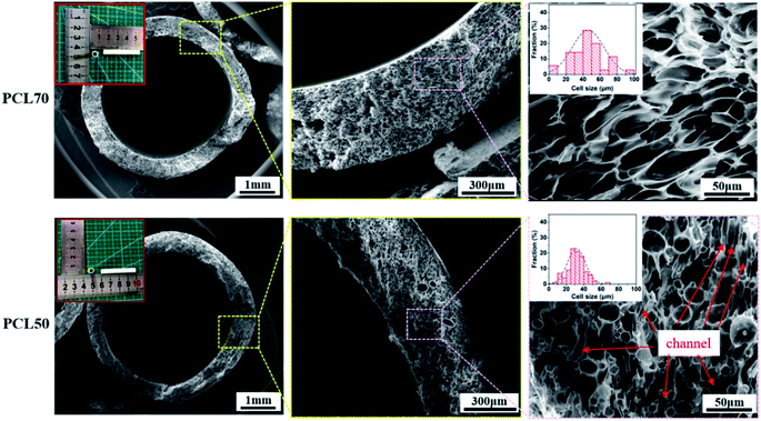
PCL70 and PCL50 blends were selected to be foamed into micro porous tubular scaffolds. As illustrated in Fig. 9, uniform tubular porous scaffolds were obtained with the same foaming process for both the PCL70 and PCL50 samples (ESI S3†). Generally, the pore size showed a gradient change across the thickness of the tube, as in “skin-core” microstructures. A number of pores with diameters of greater than 30 μm were located in the core zones of the samples, while some pores smaller than 10 μm were detected near the inner and outer surfaces of the scaffolds. This non-uniform pore gradient tendency corresponded to the restricted surfaces of scaffolds. In order to obtain homogeneous pore distribution, pore size could be increased by improving foaming temperature.9 Meanwhile, additional process, surface etching or ultrasonic treatment,36,37 could be used to improve the porosity of outer and inner surface of scaffolds. The non-uniform adsorption and desorption characteristics of ScCO2 in polymers prompt the non-homogeneous nucleation and growth of pores.38 Comparison the pore morphologies for both foamed samples in the core regions showed that pore size distributions were similar.The average pore size and open-pore content were 48 ± 1.4 μm and 72 ± 2.1% respectively, for porous PCL70 scaffolds. Prominent orientations of pores perpendicular to the thickness of the tube were clearly seen, and the aspect ratio of pores was about 3![[thin space (1/6-em)]](https://www.rsc.org/images/entities/char_2009.gif) :
:![[thin space (1/6-em)]](https://www.rsc.org/images/entities/char_2009.gif) 1. Related reports have found that a certain degree of orientation in porous structures is efficient for the growth and migration of cells in the tissue engineering field.24,38 The pore morphology for the PCL50 porous scaffolds differed greatly from that of PCL70. No regularly oriented pores were found because the co-continuous PEO phases hindered the orientation of cell nucleation and growth. The average pore size decreased to 30 ± 1.0 μm, but the open-pore content improved to 79 ± 1.9% compared with foamed PCL70. This changes can be explained by the fact that interconnected channels were formed after the PEO leaching process. The interconnected channels together with the open pores during cell growing build one mixed microstructure which enhances the total open-pore content of the PCL50 foamed sample.
1. Related reports have found that a certain degree of orientation in porous structures is efficient for the growth and migration of cells in the tissue engineering field.24,38 The pore morphology for the PCL50 porous scaffolds differed greatly from that of PCL70. No regularly oriented pores were found because the co-continuous PEO phases hindered the orientation of cell nucleation and growth. The average pore size decreased to 30 ± 1.0 μm, but the open-pore content improved to 79 ± 1.9% compared with foamed PCL70. This changes can be explained by the fact that interconnected channels were formed after the PEO leaching process. The interconnected channels together with the open pores during cell growing build one mixed microstructure which enhances the total open-pore content of the PCL50 foamed sample.
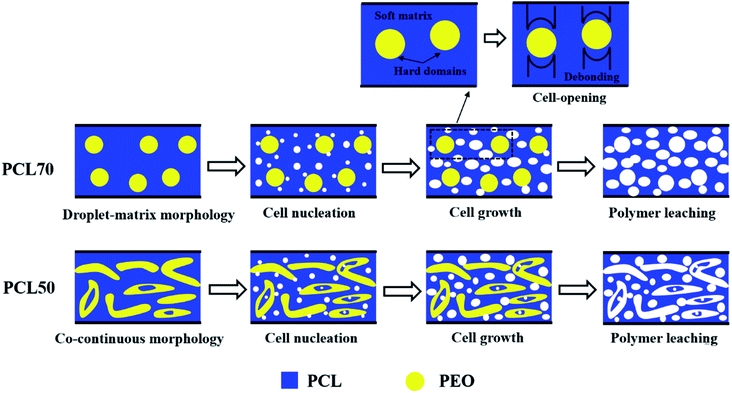
To produce foams with high open-pore contents, an efficient strategy is to melt-blend two semi-crystalline polymers with different crystallization temperatures (Tc) to maximize the stiffness contrast between the hard and soft regions in the polymer matrix.39 The cell-opening mechanisms for the PCL70 and PCL50 tubular porous scaffolds are illustrated in Fig. 10. In the same confined space, two possible cell-opening mechanisms were proposed depending on the polymer blend and its phase morphology. As shown in Fig. 10(a), PCL with a low-Tc formed matrix which was soft, and PEO with a high-Tc formed hard dispersed phases (ESI S4†). Theoretically, cell nucleation often occurs in the PCL matrix and around the PCL/PEO interface, preferentially where there are higher gas concentrations and lower activation energy barriers.40 Because of the different stiffnesses and shrinkages of PCL and PEO, the debonding process between the soft PCL matrix and hard spherical PEO domains initiated cell opening during cell growth. Fig. 10(b) exhibits the cell opening mechanism for PCL50 with its co-continuous phase morphology. More heterophasic nucleation points appeared in the PCL matrix, other than on the PCL/PEO interface, compared with in PCL70 because of the higher interface bonding force. More open cells were generated by the same cell-opening strategy as in foamed PCL70. However, the leaching process contributed more to the open-pore content. On one hand, the leached PEO phases drag the surrounding PCL cells. On the other hand, long channels originating from the leached PEO occurred. This mixed porous microstructure that combines PCL's open cells and interconnected channels can improve the open-pore content of foamed PCL50 samples.
3.6 Mechanical properties
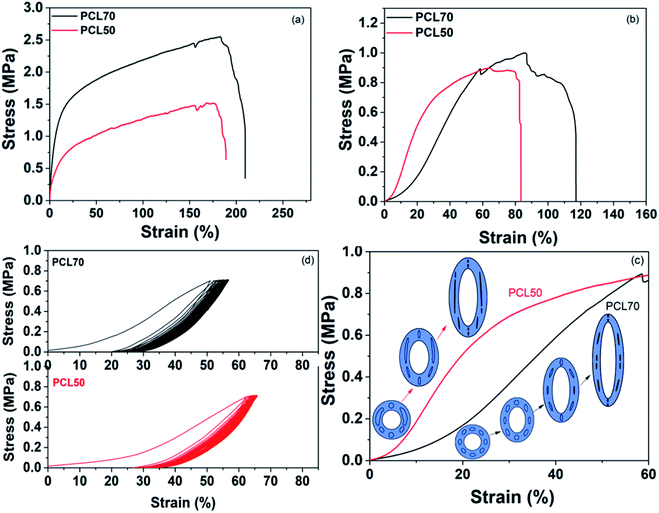
The tensile properties in the longitudinal and circumferential directions significantly influence the application of vascular tissue engineering scaffolds. The device stiffness and strength are important characteristics that define the interface with existing tissue and the pressure tolerance of the vascular scaffolds.41,42 Fig. 11(a) shows that the longitudinal strength and modulus of foamed PCL70 was bigger than that of PCL50. PCL70 also showed a slightly higher longitudinal elongation value than that of the PCL50 scaffold. This result is due to the large wall thickness and fibrillation among the cell walls for foamed PCL70. Both scaffolds meet the requirements of a human's brain veins.43,44 The toe region is one characteristic of the mechanical properties of a blood vessel.45 The circumferential stress–strain curve indicates that the toe region of the PCL70 porous scaffolds was around 25%, while that of PCL50 was only less 10%. This change was attributed to cell deformation during the tensile process. The evolutions of cell deformation for the PCL70 and PCL50 samples are illustrated in Fig. 11(c). At the beginning of the bulk deformation of the PCL70 microtube, some orientated ellipsoidal-shaped cells first deformed to a spherical shape, prior to a decrease of the cell wall thickness along the tensile force direction. That strain process needs only a little stress to have toe regions form. Since no orientated cells and only open cells combined with interconnected channels existed in the PCL50 scaffold, the wall thicknesses of the channels and irregular cells decreased rapidly. This means that the tensile stress can increase sharply without having a toe region.Cyclical properties are a critical attribute of vascular tissue engineering scaffolds because blood vessels are constantly subjected to blood pressure.46 The cyclical tensile properties of PCL70 and PCL50 were characterized in the circumferential direction for 30 cycles. Fig. 11(d) shows that both the PCL70 and PCL50 scaffolds showed a larger hysteresis loop in the first cycle, and the hysteresis stayed the same in the following cycles. This result demonstrates that the energy dissipation and structure relaxation mostly happened in the first cycle. Moreover, the PCL70 scaffolds exhibited a relatively small initial energy dissipation and larger recoverability that could be maintained in the cyclical tests. The PCL50 scaffolds, however, showed poor recoverability because of the low elongation. Hence, PCL70 could better resemble the nonlinear mechanical properties in native blood vessels than could the PCL50 scaffold, even with its smaller open-pore content.
3.7 Cell morphology
The structure of a cytoskeleton can reflect the proliferation of cells and the cell morphology evolution to a certain extent. The nucleus is well known for containing the cell's regulatory genes, which can control protein expression and affect cell behaviors.47 Fig. 12 shows the cytoskeleton and nuclei of HUVECs cultured on PCL70 and PCL50 porous tubular scaffolds at days 1, 3, and 5. The figure shows that with increasing culture time, the cell morphologies on both porous scaffolds tended to be more complete and mature. The nuclei were flat and liable to spread more fully, indicating that both high-interconnectivity porous scaffolds had a strong interaction with cells and were favourable for cell attachment and proliferation.48 Additionally, the cytoskeletons of HUVECs on the PCL70 scaffold were stretched along certain a orientation direction, and the nuclei tended to have spindle-shaped growth. This results could be attributed to the fact that the highly interconnected porous structure with fibrils shown previously in Fig. 9 (top row, right image), can induce directional cell growth. Compared with the PCL70 scaffold, HUVECs on the PCL50 scaffold had higher density and larger spreading area. These results coincided with pore morphology results that showed more channels and a higher pore density detected in porous scaffolds. The channel-pores mixed structures provided more spaces for cell proliferation and migration.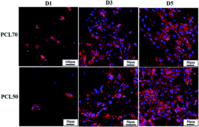 | ||
| Fig. 12 Morphology evolution of the cytoskeleton (red) and nucleus (blue) of HUVECs on PCL70 and PCL50 porous scaffolds at days 1, 3, and 5. | ||
4. Conclusions
In this study, small-diameter, porous vascular tissue engineering scaffolds were fabricated by combining eco-friendly SCF micro foaming and polymer leaching. Immiscible PCL/PEO blends with various phase morphologies were prepared. The effects of the blend composition on the foaming behaviour and pore morphology were discussed. As PEO content increased, the pore size decreased while the pore density increased. After the leaching process, highly interconnected pore structures were obtained in all samples. Fibrillated structures at the nano-scale among the cell walls were detected for the foamed PCL80 and PCL70 blends, which had a droplet-matrix morphology. The maximum porosity and open-pore content were obtained in the foamed PCL70, both of which were more than 85%. Pore statistical results demonstrated that the leaching process made a greater contribution to the open-cell content of PCL50, as opposed to PCL70. Average pore sizes were 48 ± 1.4 μm and 30 ± 1.0 μm, respectively for the micro porous PCL70 and PCL50 tubular scaffolds. Prominent orientated pores were found in PCL70 tubular scaffold, while a mixed microstructure combining interconnected channels and open cells occurred in the PCL50 tubular scaffold. Tensile properties showed that the PCL70 scaffold had a greater longitudinal tensile strength and a 25% toe region. A larger recoverability was obtained for the PCL70 scaffold during cyclical tests. Cytoskeleton assay results revealed that HUVECs tended to align along the direction of the pore orientation in the PCL70 scaffold, whereas higher density and spreading areas of HUVECs were discovered in the PCL50 scaffolds.Conflicts of interest
There are no conflicts to declare.Acknowledgements
This work was sponsored by the Joint Funds of the National Natural Science Foundation of China (No. U1909219), International Technological Cooperation Project (2015DFA30550), Scientific and Technological Research Project of Henan Province (182102210188, 172102210489). Zhengzhou University Doctoral Talent Program for corresponding author was also appreciated.References
- S. J. Hollister, Nat. Mater., 2005, 4, 518 CrossRef CAS.
- N. Ngadiman, N. Yusof, A. Idris, E. Fallahiarezoudar and D. Kurniawan, Polymers, 2018, 10, 353 CrossRef.
- S. Park, J. Kim, M.-K. Lee, C. Park, H.-D. Jung, H.-E. Kim and T.-S. Jang, Mater. Des., 2019, 181, 108079 CrossRef CAS.
- X. Ren, Y. Feng, J. Guo, H. Wang, Q. Li, J. Yang, X. Hao, J. Lv, N. Ma and W. Li, Chem. Soc. Rev., 2015, 44, 5680–5742 RSC.
- H. Qu, H. Fu, Z. Han and Y. Sun, RSC Adv., 2019, 9, 26252–26262 RSC.
- J. Ju, X. Peng, K. Huang, L. Li, X. Liu, C. Chitrakar, L. Chang, Z. Gu and T. Kuang, Polymer, 2019, 180, 121707 CrossRef CAS.
- Q. L. Loh and C. Choong, Tissue Eng., Part B, 2013, 19, 485–502 CrossRef CAS PubMed.
- X. Liu, Y. Won and P. X. Ma, Biomaterials, 2006, 27, 3980–3987 CrossRef CAS.
- K. Zhang, Y. Wang, J. Jiang, X. Wang, J. Hou, S. Sun and Q. Li, J. Mater. Sci., 2019, 54, 5112–5126 CrossRef CAS.
- R. J. Mondschein, A. Kanitkar, C. B. Williams, S. S. Verbridge and T. E. Long, Biomaterials, 2017, 140, 170–188 CrossRef CAS.
- Z. Niu, X. Wang, X. Meng, X. Guo, Y. Jiang, Y. Xu, Q. Li and C. Shen, Biomed. Mater., 2019, 14, 035006 CrossRef CAS PubMed.
- W. Zhang, I. Ullah, L. Shi, Y. Zhang, H. Ou, J. Zhou, M. W. Ullah, X. Zhang and W. Li, Mater. Des., 2019, 107946 CrossRef CAS.
- D. Yin, J. Mi, H. Zhou, X. Wang and H. Fu, Polym. Degrad. Stab., 2019, 167, 228–240 CrossRef CAS.
- X. Zhang, W. Ding, N. Zhao, J. Chen and C. B. Park, Ind. Eng. Chem. Res., 2018, 57, 2094–2104 CrossRef CAS.
- J. Capes, H. Ando and R. Cameron, Mater. Sci., 2005, 16, 1069–1075 CAS.
- H. Li, C. Hu, H. Yu and C. Chen, RSC Adv., 2018, 8, 3736–3749 RSC.
- L. Wu, D. Jing and J. Ding, Biomaterials, 2006, 27, 185–191 CrossRef CAS PubMed.
- S. Li, C. Song, S. Yang, W. Yu, W. Zhang, G. Zhang, Z. Xi and E. Lu, Acta Biomater., 2019, 94, 253–267 CrossRef CAS PubMed.
- X. Liang, P. Duan, J. Gao, R. Guo, Z. Qu, X. Li, Y. He, H. Yao and J. Ding, ACS Biomater. Sci. Eng., 2018, 4, 3506–3521 CrossRef CAS.
- S. Sun, Q. Li, N. Zhao, J. Jiang, K. Zhang, J. Hou, X. Wang and G. Liu, Polym. Adv. Technol., 2018, 29, 3065–3074 CrossRef CAS.
- J. Wang, C. Lin, X. Gao, Z. Zheng, M. Lv, J. Sun and Z. Zhang, RSC Adv., 2018, 8, 32304–32316 RSC.
- H. Wang, D. Tong, L. Wang, L. Chen, N. Yu and Z. Li, Polym. Degrad. Stab., 2017, 140, 64–73 CrossRef CAS.
- P. Basu, A. Repanas, A. Chatterjee, B. Glasmacher, U. NarendraKumar and I. Manjubala, Mater. Lett., 2017, 195, 10–13 CrossRef CAS.
- T. Kuang, F. Chen, L. Chang, Y. Zhao, D. Fu, X. Gong and X. Peng, Chem. Eng. J., 2017, 307, 1017–1025 CrossRef CAS.
- J. Zhang, S. Yang, X. Yang, Z. Xi, L. Zhao, L. Cen, E. Lu and Y. Yang, ACS Biomater. Sci. Eng., 2018, 4, 694–706 CrossRef CAS.
- Y. Fei, W. Fang, M. Zhong, J. Jin, P. Fan, J. Yang, Z. Fei, F. Chen and T. Kuang, Polymers, 2018, 10, 276 CrossRef PubMed.
- H. Zhou, X. Wang, Z. Du, H. Li and K. Yu, Polym. Eng. Sci., 2015, 55, 988–994 CrossRef CAS.
- A. Codou, A. Anstey, M. Misra and A. K. Mohanty, RSC Adv., 2018, 8, 15709–15724 RSC.
- M. Liang, P. Liang, W. Fan, C. Qian, X. Xin, J. Shi and G. Nan, Mater. Des., 2015, 88, 177–185 CrossRef CAS.
- Z. Xi, F. Zhang, H. Zhong, T. Liu, L. Zhao and L.-S. Turng, Polym. Eng. Sci., 2014, 54, 2739–2745 CrossRef CAS.
- Y. Fei, W. Fang, M. Zhong, J. Jin, P. Fan, J. Yang, Z. Fei, L. Xu and F. Chen, Polymers, 2019, 11, 106 CrossRef PubMed.
- A. Huang, Y. Jiang, B. Napiwocki, H. Mi, X. Peng and L.-S. Turng, RSC Adv., 2017, 7, 43432–43444 RSC.
- A. Thangprasert, C. Tansakul, N. Thuaksubun and J. Meesane, Mater. Des., 2019, 183, 108113 CrossRef CAS.
- H. Zhou, M. Zhao, Z. Qu, J. Mi, X. Wang and Y. Deng, J. Polym. Environ., 2018, 26, 3564–3573 CrossRef CAS.
- J. Yu, L. Song, F. Chen, P. Fan, L. Sun, M. Zhong and J. Yang, Mater. Today Commun., 2016, 9, 1–6 CrossRef.
- N. Zhao, Z. Lv, J. Ma, C. Zhu and Q. Li, Eur. Polym. J., 2019, 110, 31–40 CrossRef CAS.
- J. Wang, W. Zhai, J. Ling, B. Shen, W. Zheng and C. B. Park, Ind. Eng. Chem. Res., 2011, 50, 13840–13847 CrossRef CAS.
- X. Liao, H. Zhang, Y. Wang, L. Wu and G. Li, RSC Adv., 2014, 4, 45109–45117 RSC.
- A. R. Boccaccini, J. J. Blaker, V. Maquet, R. Day and R. Jérôme, Mater. Sci. Eng., C, 2005, 25, 23–31 CrossRef.
- P. C. Lee, J. Wang and C. B. Park, Ind. Eng. Chem. Res., 2006, 45, 175–181 CrossRef CAS.
- T. Bai, B. Dong, M. Xiao, H. Liu, N. Wang, Y. Wang, C. Wang, C. Liu, W. Cao and J. Zhang, Macromol. Mater. Eng., 2018, 303, 1800110 CrossRef.
- A. Abdal-hay, M. Bartnikowski, S. Hamlet and S. Ivanovski, Mater. Sci. Eng., C, 2018, 82, 10–18 CrossRef CAS PubMed.
- H.-Y. Mi, X. Jing, E. Yu, X. Wang, Q. Li and L.-S. Turng, J. Mech. Behav. Biomed. Mater., 2018, 78, 433–441 CrossRef CAS PubMed.
- Z. Lv, N. Zhao, Z. Wu, C. Zhu and Q. Li, Ind. Eng. Chem. Res., 2018, 57, 12951–12958 CrossRef CAS.
- C. Lane-Donovan and J. Herz, eLife, 2017, 6, e31808 CrossRef PubMed.
- C. T. Laurencin and J. W. Freeman, Biomaterials, 2005, 26, 7530–7536 CrossRef CAS PubMed.
- X. Li, X. Wang, D. Yao, J. Jiang, X. Guo, Y. Gao, Q. Li and C. Shen, Colloids Surf., B, 2018, 171, 461–467 CrossRef CAS PubMed.
- C. M. Murphy, M. G. Haugh and F. J. O'brien, Biomaterials, 2010, 31, 461–466 CrossRef CAS PubMed.
Footnote |
| † Electronic supplementary information (ESI) available. See DOI: 10.1039/d0ra00956c |
| This journal is © The Royal Society of Chemistry 2020 |


