 Open Access Article
Synthesis and photocatalytic properties of three dimensional laminated structure anatase TiO2/nano-Fe0 with exposed (001) facets
Yeshuo Dong *a and
Fanjun Mengb
aSchool of Environmental and Municipal Engineering, Qingdao University of Technology, Qingdao, 266033, China. E-mail: dysh_1127@aliyun.com
bCollege of Chemistry, Chemical Engineering and Materials Science, Shandong Normal University, Jinan, 250014, China
First published on 24th March 2020
Abstract
Three dimensional laminated structure anatase TiO2/nano-Fe0 with exposed (001) facets used as photocatalysts were synthesized by a two-step solvothermal route and a liquid phase reduction deposition method. The resulting samples were characterized by X-ray diffraction, X-ray photoelectron spectroscopy, ultraviolet-visible diffuse reflectance spectroscopy, scanning electron microscopy, transmission electron microscopy and selected-area electron diffraction. Characterization and experimental results indicated that the three dimensional laminated structure of anatase TiO2 was assembled by two dimensional TiO2-sheets with a thickness of approximately 30 nm. The three dimensional laminated structure anatase TiO2/nano-Fe0 photocatalysts with improved visible-light responsive capability, high charge-hole mobility, and low electron–hole recombination exhibited higher photocatalytic performance in the photocatalytic degradation of methylene blue. The composite of nano-Fe0 and TiO2 could effectively promote the generation of hydroxyl radicals (˙OH) with a synergistic effect and Photo-Fenton theory. This study provided new insights into the fabrication and practical application of high-performance photocatalysts in degrading organic pollutants.
1. Introduction
The increasingly serious problems of energy shortages and environmental pollution have become a critical obstacle to the sustainable development of society.1,2 The photocatalysis technology based on inorganic semiconductor catalysis materials provides us with an ideal new way of energy utilization and environmental pollution control.3–5 Many inorganic semiconductor materials have been widely studied and applied in the field of environmental protection, dye-sensitized solar cells, photoelectric conversion and water decomposition hydrogen production due to their unique structural characteristics and excellent physical and chemical properties.6–8 As we all know, in many inorganic semiconductor materials, TiO2 has been deeply studied for a long time due to its simple processing, stable chemical properties and being harmless to the environment and humans.9,10 Because of these excellent characteristics, it is usually used in the treatment of organic wastewater (such as dyes). Compared with the anodic oxidation,11 electrocoagulation,12 adsorption,13,14 and biodegradation methods,15 it has the advantages of strong oxidation, low energy consumption and simple operation. However, nano-TiO2 grains have the defects of low visible light utilization, easy recombination of photogenerated electrons and holes, and easy agglomeration and deactivation at nano scale.16,17 The studies show that for a long time, the research on the design and preparation of TiO2 semiconductor materials is the key to improve the comprehensive performance of photocatalysis.18,19 It is the core scientific problem in the field of TiO2 semiconductor photocatalysis that the materials have high efficiency of excitation light response, excellent electron hole yield and separation characteristics.20–22 Therefore, scholars have carried out a series of research on the reconstruction of self structure and auxiliary modification based on the design and preparation of TiO2 morphology and structure.16,17,23,24In recent years, it has been shown that with the development of crystal surface engineering, it is popular to adjust the performance of photocatalytic materials by adjusting the exposure degree of crystal surface in the study of TiO2 structure reconstruction.25,26 In 2008, the uniform anatase TiO2 single crystals were synthesized with a large percentage (47%) of reactive (001) facets using hydrofluoric acid as a morphology controlling agent.27 This material shows a higher photocatalytic activity than that of conventional TiO2 with (101) facets. Subsequently, the research of anatase TiO2 single crystal with (001) facets has attracted great attention, and on this basis, TiO2 nanosheets with higher (001) facets exposure ratio have been synthesized.28–30 When the proportion of anatase TiO2 with exposed (001) facets increased, the photocatalytic activity of TiO2 improved significantly. However, TiO2 nanosheets usually have the defects of easy agglomeration, easy lose electron and poor dispersion.25 Therefore, researchers have used different titanium sources and improved synthesis methods to realize the self-assembly of TiO2 single crystal sheets with (001) facets exposed, and some TiO2 catalysts with multi-level structure such as spherical and flower structure formed by the self-assembly of TiO2 single crystal sheets with (001) facets have been successively synthesized.31–33 The self-assembly structure of the single crystal sheets can effectively improve the transmission efficiency of photogenerated electrons and promote the separation of photogenerated electrons and holes, thus greatly improving the photocatalytic activity and photoelectric effect.34,35 Therefore, the research on the design and preparation of TiO2 materials with (001) facets exposed sheets structure has great significance and broad application prospects.21,36,37
In the study of TiO2 assisted modification, the addition of transition and/or noble metals is one of the promising methods to improve the photocatalytic activity and photoelectric effect of TiO2.38–41 Due to the formation of doping energy and the rapid transfer of the photogenerated electrons from the semiconductors to the dopants, the doped metal such as Fe, Pt, Mo, Cr, Ag and Au can reduce the recombination rate of electrons and holes.42 As a new environmental remediation engineering material, nano-zerovalent iron (nano-Fe0) has been widely used in the field of environmental remediation. Nano-Fe0 has the excellent properties of large specific surface area, high chemical reaction activity and excellent surface characteristics, which make it suitable for the treatment of many pollutants that are difficult to biodegrade.43–45 Up to now, nano-Fe0 has been proved to be able to effectively remove a variety of pollutants, including nitroaromatic compounds, organic halogenated compounds, inorganic nitrates, polycyclic aromatic hydrocarbons, organic dyes, a variety of heavy metals and antibiotic drugs.46,47 However, the high activity of nano-Fe0 makes its stability in the air very poor, and it is easy to be oxidized or even self-ignited after contacting with oxygen.48,49 Because of its nano size, it is easy to agglomerate in the water, which limits the application of nano-Fe0 materials in the actual water treatment process.50,51 Many results show that the combination of nano-Fe0 and TiO2 can effectively improve the stability of nano-Fe0 and the dispersion in the water.52 At the same time, this combination can effectively promote the separation of photogenerated electron holes, enhance the photoelectric effect, and expand the visible light response range. Moreover, in the process of photocatalysis, this combination can not only compensate the consumption of nano-Fe0 (dynamic circulation reaction mechanism),53 but also form the Photo-Fenton effect; Fe3+; Fe2+; TiO2 and H2O2 coexisting in the system will promote the production of hydroxyl radicals under the action of ultraviolet light, so as to improve the photocatalytic activity and pollutant removal rate.52,54,55
In this work, we aim to synthesize a highly active composite TiO2 photocatalyst with (001) facets exposed and visible light response by combining nano-Fe0. Therefore, under the action of hydrofluoric acid, isobutanol and isopropanol, three dimensional laminated structure anatase TiO2/nano-Fe0 with exposed (001) facets (3D-TiO2/nano-Fe0) were synthesized by a two-step solvothermal route and a liquid phase reduction deposition method. The structure and morphology of samples were characterized by X-ray diffraction (XRD), scanning electron microscopy (SEM), transmission electron microscope (TEM), X-ray photoelectron spectroscopy (XPS) and UV-vis diffuse reflectance spectra (UV-vis DRS), respectively. Besides, methylene blue was used as the degradation substrate. The synergistic effect and photocatalytic properties of 3D-TiO2/nano-Fe0 photocatalysts on methylene blue were investigated by adjusting the pH value, the concentration of dissolved oxygen and the band of excitation light.
2. Experimental methods
2.1 Synthesis of 3D laminated structure anatase TiO2 with exposed (001) facets
The 3D laminated structure anatase TiO2 with exposed (001) facets (3D-TiO2) were synthesized in a two-step solvothermal route (Scheme 1). In this work, hydrofluoric acid (HF), isobutanol and isopropanol were used as the morphology controlling agent.56 We synthesized these 3D-TiO2 by controlling the interaction characteristics of hydrofluoric acid (HF), isobutanol and isopropanol on the crystal facets.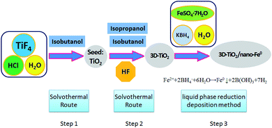 | ||
| Scheme 1 Synthesis route of 3D laminated structure anatase TiO2/nano-Fe0 photocatalysts (3D-TiO2/nano-Fe0). | ||
Firstly, titanium tetrafluoride (TiF4; Sigma-Aldrich) was dissolved in hydrochloric acid solution under vigorous stirring to give a concentration of 0.04 mol L−1 with the pH value changed to 2.60 mL of the above TiF4 solution (0.04 mol L−1) and 10 mL of isobutanol were added into a 100 mL Teflon-lined stainless steel autoclave. The autoclave was kept at 180 °C for 6 h in an electric oven. After reaction, the white solid TiO2 particles were harvested by centrifugation, cleaning and drying.
Secondly, the obtained white solid TiO2 particles were used as seeds. 10 mL of isobutanol, 20 mL of isopropanol and 0.1 mL of hydrofluoric acid (HF, 40 wt%) were added into a 50 mL Teflon-lined stainless steel auto-clave. The autoclave was kept at 200 °C for 15 h in an electric oven. After centrifugation, washing and drying, the 3D-TiO2 were harvested. The surface fluorine was removed at 500 °C for 90 min. Then, the samples were cooled to room temperature for further activity experiments and characterization.
2.2 Synthesis of 3D laminated structure anatase TiO2/nano-Fe0 photocatalysts
The 3D laminated structure anatase TiO2/nano-Fe0 photocatalysts (3D-TiO2/nano-Fe0) were synthesized by a liquid phase reduction deposition method (Scheme 1). In a typical process, the prepared 3D laminated structure anatase TiO2 samples (0.8 g), C2H5OH (50 mL) and FeSO4·7H2O solution (0.6 mol L−1; 100 mL) were mixed, stirred and ultrasonic dispersion 30 min under nitrogen protection. And then the mixture was centrifuged and dried to get the solid particles M. Then, M (1.0 g) and C2H5OH (60 mL) were mixed and stirred constantly for 30 min to get the component X. Alkaline KBH4 solution (pH = 9; 0.4 mol L−1) was dropped in X under stirring, and the reaction mixture was treated by ultrasonic intermittently until the black solid suspension was obtained. After precipitation, filter, cleaning, rotary steam drying. Finally, the 3D-TiO2/nano-Fe0 photocatalysts were obtained and stored in the anaerobic environment.2.3 Characterization of materials
The morphology and structure of the as-synthesized 3D-TiO2/nano-Fe0 photocatalysts were investigated by X-ray spectroscopy (XRD, Bruker D8 Advance), scanning electron microscopy (SEM, JEOL-JSM6400F), UV-vis diffuse reflectance spectra (UV-vis DRS, Lambda 35) and transmission electron microscopy (TEM, JEM-2100) equipped with a selected-area electron diffraction (SAED). X-ray photoelectron spectroscopy (XPS) measurements were conducted by a Kratos AXIS Ultra DLD XPS system.2.4 Photocatalytic properties measurement
Methylene blue (thiazine dye), an environment pollutant, was selected to evaluate the photocatalytic activities of 3D-TiO2/nano-Fe0 photocatalysts under UV and visible light irradiation. The experiments were conducted using an airtight reactor. High-purity nitrogen and oxygen were purged continuously to maintain anoxic and oxic conditions. A 350W UV-light lamp was positioned within the central part of the photoreactor and cooling water was circulated through a pyrex jacket surrounding the lamp. The reactants were taken from the suspension at regular time intervals and immediately filtered through a 0.22 μm polytetrafluoroethylene filter membrane, and the filtrate was collected for analysis. An UV-vis absorption spectrophotometer (UV-2500, Shimadzu) was used to determine the absorbance of products.3. Results and discussion
3.1 Characterization
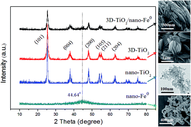
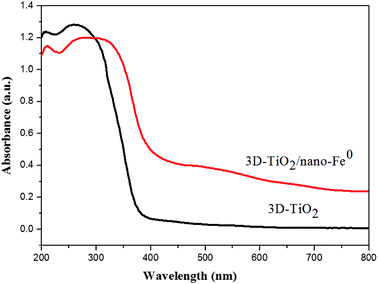
In this work, the structure of samples have been confirmed by X-ray diffraction (XRD), and the diffraction pattern are shown in Fig. 1. Anatase TiO2 was observed in the samples, which indicated that its crystallinity was not affected by the nano-Fe0. The diffraction patterns of the prepared anatase TiO2 correlated well with the standard peaks (JCPDS card no. 21-1272), with the three most obvious diffraction peaks observed at 25.5° (101), 37.9° (004), and 48.2° (200). The (004) diffraction peak can be identified in the XRD pattern, which indicated the TiO2 nanostructures along the (001) crystallographic direction.28,57 In the curve of both the nano-Fe0 and 3D-TiO2/nano-Fe0, the characteristic peak at the 2θ of 44.64° belonged to α-Fe (110) crystal was observed, suggesting that in the 3D-TiO2/nano-Fe0 composite the nano-Fe0 keeps its original properties.53 The crystallite sizes of the 3D-TiO2/nano-Fe0, 3D-TiO2, nano-Fe0 and nano-TiO2 were obtained by both SEM images analysis (Fig. 3 and 4) and Scherrer formula calculation, obtaining average values of 3.5 μm, 3 μm, 80 nm and 10 nm, respectively.Considering that band structure plays a key role in determining the photocatalytic activity of semiconductors, the UV-vis DRS of the synthesized samples were performed. As shown in Fig. 2, a significant increase was found in the visible absorption of 3D-TiO2/nano-Fe0 photocatalysts compared with 3D-TiO2. Concerning to the band gap energy (Eg) values, there was a visible-shift in the absorption edge for 3D-TiO2/nano-Fe0 photocatalysts compared to the 3D-TiO2. Moreover, compared with the optical absorption of 3D-TiO2 cut off at 385 nm, it can be seen that the absorption peak of the 3D-TiO2/nano-Fe0 photocatalysts in the visible region was stronger than that of the 3D-TiO2. It indicates that the prepared 3D-TiO2/nano-Fe0 photocatalysts showed a photoresponse red shift effect by reducing the band gap energy of TiO2, which is consistent with the photocatalytic activity shown in Fig. 8
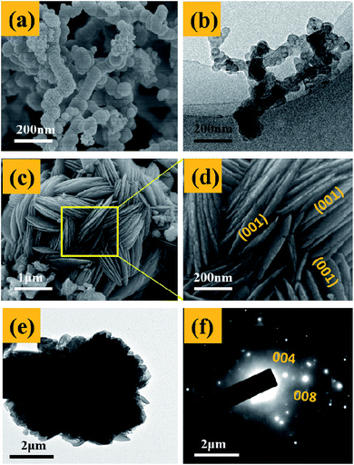
Fig. 3 presents the SEM and TEM images of the nano-Fe0 (Fig. 3a and b) and 3D-TiO2 (Fig. 3c–e). As shown in Fig. 3a and b, the morphology of nano-Fe0 is ball chain-shaped with a size of approximately 50 nm, which generally has agglomeration phenomenon. SEM images in Fig. 3c and d showed the general morphology of the 3D-TiO2, which were entirely composed of 3D laminated structures with a size of approximately 3 μm. The 3D laminated structures were assembled by 2D TiO2-sheets with a thickness of approximately 30 nm. The microstructures of the 3D-TiO2 were investigated by TEM and selected-area electron diffraction (SAED). TEM image showed the 3D laminated structures in which 3D-TiO2 can be easily identified in Fig. 3e. And the corresponding SAED patterns shown in Fig. 3f indicated that the top and bottom facets of the TiO2 nanosheets were the (001) facets.31 Fig. 4 presents the SEM (a and b) and TEM (c and d) images of the 3D-TiO2/nano-Fe0. According to SEM, we can see clearly that there are many nano-Fe0 particles on the surface of 3D-TiO2. Moreover, the high-resolution TEM image recorded in Fig. 4d clearly shows the atomic planes with the lattice spacing of 0.204 nm and 0.19 nm, which corresponding to the (110) planes of α-Fe and the (200) planes of TiO2, respectively. This result proved the formation of heterojunctions between nano-Fe0 and TiO2. And the formed heterojunction structure can not only block the recombination of the photogenerated electron–hole effectively, but also reduce the band gap energy of TiO2. Thus, the 3D-TiO2/nano-Fe0 photocatalysts show a high response and high catalytic activity in the visible region, which is consistent with the analysis results of the UV-vis DRS shown in Fig. 2.
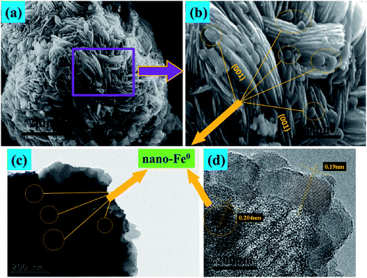 | ||
| Fig. 4 (a) and (b), SEM images of typical 3D-TiO2/nano-Fe0 photocatalysts. (c) and (d), TEM and HRTEM images of 3D-TiO2/nano-Fe0 photocatalysts. | ||
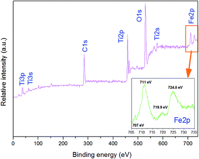
As shown in Fig. 5, XPS was used to determine the surface chemical compositions and chemical states of the resultant crystals. It can be seen that 3D-TiO2/nano-Fe0 contain Ti, O, and C elements, with sharp photoelectron peaks appearing at binding energies of 458 eV, 531 eV and 285 eV, respectively.58 The C 1s (285 eV) peak is attributed to the adventitious hydrocarbon from XPS instrument itself. Fig. 5 (inset) is the XPS of the nano-Fe0 in the 2p region. The photoelectron peaks appearing at binding energies of 711 eV, 719.9 eV and 724.5 eV represent the 2p3/2 peak, the vibrational satellite peak of 2p3/2 and 2p1/2 peak, respectively. The binding energy values of Fe element show that there are iron oxides on the surface of nano-Fe0. Besides, there is a small photoelectron peak at 707 eV, which represent the 2p3/2 peak of nano-Fe0. The analysis shows that the surface of nano-Fe0 is covered by iron oxides.
3.2 Photocatalytic performance
Methylene blue (thiazine dye) is an aromatic heterocyclic compound, which has important applications in chemical indicators, pharmaceutical production, dyes (pigments) preparation and other fields.14,59 However, dye wastewater is characterized by complex composition, high chroma, large discharge and poor biodegradability, and mostly contains carcinogenic, teratogenic and mutagenic substances.2,60 Traditional wastewater treatment technology is weak in mineralization of refractory organics, so it can not be completely transformed into harmless small molecules.61 Due to the limitations of traditional water treatment technology, aiming at the scientific problem of degradation and removal of methylene blue, the related experiments were carried out in this paper. Therefore, based on the characteristics and mechanism of photocatalytic oxidation of TiO2, the degradation of methylene blue by TiO2 photocatalysis technology was studied in this work.As shown in Fig. 6, the effect of the initial pH value on the degradation efficiency with different samples are investigated. It can be seen that the initial pH value of the dye aqueous solution affects the degradation efficiency obviously for both 3D-TiO2 and 3D-TiO2/nano-Fe0, and an acidic pH value is benefit for a high degradation efficiency.62 The reason for this is that the H+ was a very key reaction factor to promote the generation of hydroxyl radicals (˙OH). According to the mechanism of the photocatalytic oxidation reaction, the isoelectric point of TiO2 is pHPZC = 6.8. In the acidic range (pH < pHPZC), the surface of catalyst is protonated and results in a positive charge surface, which can promote the photo-generated electron transfer to the catalyst surface.63 The comparison of dark reaction experiments showed that the 3D-TiO2/nano-Fe0 photocatalyst had higher degradation activity in the dark reaction. This is because in the absence of light conditions, nano-Fe0 can play a priority role in the degradation of dyes. Moreover, the presence of iron ions in an acidic environment can cause flocculation, which will also increase the degradation efficiency.64
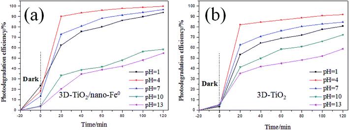 | ||
| Fig. 6 Comparion on photocatalytic degradation activity of samples under different pH. (a) 3D-TiO2/nano-Fe0; (b) 3D-TiO2. | ||
As shown in Fig. 6a, for the 3D-TiO2/nano-Fe0 photocatalyst, the degradation activity is low when it is in alkaline conditions. When the pH > 7, ferrous hydroxide (Fe(OH)2) was obtained due to the reaction of zerovalent iron with water produced Fe2+ and OH−. Fe(OH)2 would further transform to ferric oxides under alkaline conditions. That will destroy the balance of the reaction and accelerate nano-Fe0 consumption. Moreover, the ferric oxides will deposit onto the surface of catalysts to prevent contact with contamination. Therefore, the removal and degradation of pollutants is not conducive by the 3D-TiO2/nano-Fe0 photocatalyst in the alkaline environment.
The effect of dissolved oxygen on the degradation efficiency of methylene blue was investigated, and the results were shown in Fig. 7. It can be seen that the degradation efficiency will be higher in oxic condition for both 3D-TiO2 and 3D-TiO2/nano-Fe0. According to the principle of heterogeneous photocatalysis (eqn (1)), the dissolved oxygen can act as a reactant and an photo-electron capture agent. The dissolved oxygen will combine with photoelectron and proton to produce H2O2. Then H2O2 reacts with superoxide anion radical (˙O2−) to produce hydroxyl radical (˙OH).
 | (1) |
| Fe0 + O2 + 2H+ → Fe2+ + H2O2 → Fe3+ + HO− +˙OH | (2) |
 | (3) |
| e− + H2O2 → HO− + ˙OH | (4) |
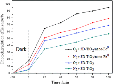 | ||
| Fig. 7 Comparion on photocatalytic degradation activity of samples under the different concentration of dissolved oxygen. | ||
For the 3D-TiO2/nano-Fe0 photocatalyst, the nano-Fe0 will reacts with dissolved oxygen and H+ to produce H2O2 (eqn (2)). This degradation step takes place via oxidizing agents such as H2O2 and other oxidative species in oxic condition which in turn produce hydroxyl radical through Fenton process (eqn (2)). Moreover, under the condition of photocatalysis, one part of H2O2 will be photolyzed into hydroxyl radical (eqn (3)), and the other part will react with photoelectrons to produce hydroxyl radical (eqn (4)). So, the 3D-TiO2/nano-Fe0 photocatalyst shows higher catalytic activity than the 3D-TiO2, which further proves that the nano-Fe0 will promote the photocatalytic activity by Photo-Fenton theory. Beside, in view of synergistic effect, the TiO2 photocatalysts can be photoexcited by UV light to generate electron–hole pairs. The nano-Fe0 on the surface of 3D-TiO2 can accelerate the charge transfer and separation, leading to the enhancement of the oxidation. In addition, the produced Fe2+ in reaction system can react with photogenerated holes to form Fe3+, and then be converted back to Fe2+ again when reacted with electrons, resulting in the prevention of hole–electron recombination and the increase in the total amounts of hydroxyl radicals.64
The degradation efficiency of methylene blue with different catalyst and light source are tested and compared, and the results are shown in Fig. 8. It is obvious that the catalytic activity of 3D-TiO2/nano-Fe0 photocatalysts was higher than 3D-TiO2 under both UV and visible light. As shown in Fig. 2, the 3D-TiO2/nano-Fe0 shows a high absorbance in the visible region, thus the 3D-TiO2/nano-Fe0 will respond to visible light and produces photocatalytic activity. This result is mainly due to the formation of heterojunction structure, which is consistent with the analysis results of the UV-vis DRS shown in Fig. 2.
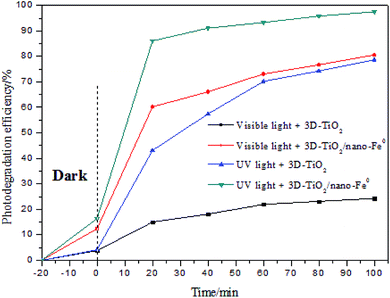 | ||
| Fig. 8 Comparion on photocatalytic degradation activity of samples under UV light and under visible light. | ||
As we all know, in the research of photocatalytic degradation of dyes, the decolorization rate is usually used as the index of photocatalytic degradation activity.65–67 However, the fading of dye only means that its chromophore is destroyed, rather than it is completely mineralized into H2O and CO2. In order to evaluate the degradation efficiency of photocatalysis strictly, we studied the relationship between the decolorization rate and CODCr removal rate. As shown in Fig. 9a, the decolorization rate is not equivalent to the CODCr removal rate. When the decolorization rate reaches 100%, the CODCr removal rate is 55%, which demonstrates that when the chromophore of dye is destroyed under the system of photocatalysis, it will lead to fading effect. After photocatalytic degradation, some intermediates that are difficult to be photocatalytic degraded will still exist in the system. Moreover, the removal efficiency of different samples for CODCr was tested showing that the 3D-TiO2/nano-Fe0 photocatalysts has a higher removal efficiency for the CODCr due to its synergistic effect and Photo-Fenton theory (Fig. 9b).
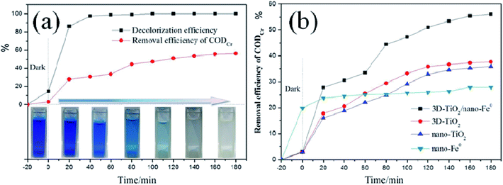 | ||
| Fig. 9 (a), Comparison of decolorization rate and CODCr in photocatalytic process. (b), CODCr removal rate under the different samples. | ||
Although it has higher accuracy to evaluate the photocatalytic efficiency with the CODCr, it is more complex. In this case, considering the trend consistency of decolorization rate and CODCr removal rate and the fast determination of decolorization rate, the decolorization rate is used as the measurement index, which is scientific and feasible.
4. Conclusions
In summary, the 3D-TiO2/nano-Fe0 photocatalysts could be synthesized by a two-step solvothermal route and a liquid phase reduction deposition method. The characterization results confirmed that the 3D-TiO2/nano-Fe0 photocatalysts had three dimensional laminated structure which assembled by two dimensional TiO2-sheets with a thickness of approximately 30 nm. Moreover, the composite of nano-Fe0 leaded to the visible light response characteristics of the catalyst. On the application side, the resultant 3D-TiO2/nano-Fe0 photocatalysts exhibited remarkable photocatalytic performance for the degradation of methylene blue, which could be largely attributed to their synergistic effect and Photo-Fenton theory. Most significantly, the 3D-TiO2/nano-Fe0 photocatalysts has a higher removal efficiency for the CODCr, which provides a new material and approach for the mineralization of organic pollutants.Conflicts of interest
There are no conflicts to declare.References
- Z. F. Huang, J. J. Zou, L. Pan, S. B. Wang, X. W. Zhang and L. Wang, Appl. Catal., B, 2014, 147, 167–174 CrossRef CAS.
- I. El Saliby, L. Erdei, J. H. Kim and H. K. Shon, Water Res., 2013, 47, 4115–4125 CrossRef CAS PubMed.
- R. G. Li, H. X. Han, F. X. Zhang, D. G. Wang and C. Li, Energy Environ. Sci., 2014, 7, 1369–1376 RSC.
- S. Jia, J. Li, G. Sui, L. Du, Y. Zhang, Y. Zhuang and B. Li, RSC Adv., 2019, 9, 31177–31185 RSC.
- R. M. Ali, M. R. Elkatory and H. A. Hamad, Fuel, 2020, 268, 117297 CrossRef CAS.
- A. Y. Meng, J. Zhang, D. F. Xu, B. Cheng and J. G. Yu, Appl. Catal., B, 2016, 198, 286–294 CrossRef CAS.
- X. Li, J. G. Yu and M. Jaroniec, Chem. Soc. Rev., 2016, 45, 2603–2636 RSC.
- K. J. Ramos-Corella, M. Sotelo-Lerma, A. A. Gil-Salido, J. L. Rubio-Pino, O. Auciello and M. A. Quevedo-Lopez, Materials and Technology, 2019, 34, 455–462 CrossRef CAS.
- C. P. Sajan, S. Wageh, A. A. Al-Ghamdi, J. G. Yu and S. W. Cao, Nano Res., 2016, 9, 3–27 CrossRef CAS.
- B. L. Yan, J. Zhou, X. Y. Liang, K. N. Song and X. T. Su, Appl. Surf. Sci., 2017, 392, 889–896 CrossRef CAS.
- H. Hamad, D. Bassyouni, E.-S. El-Ashtoukhy, N. Amin and M. Abd El-Latif, Ecotoxicol. Environ. Saf., 2018, 148, 501–512 CrossRef CAS PubMed.
- E. S. Z. El-Ashtoukhy, N. K. Amin, M. M. Abd El-Latif, D. G. Bassyouni and H. A. Hamad, J. Cleaner Prod., 2017, 167, 432–446 CrossRef CAS.
- D. Bassyouni, M. Mohamed, E.-S. El-Ashtoukhy, M. A. El-Latif, A. Zaatout and H. Hamad, Microchem. J., 2019, 149, 103998 CrossRef.
- H. Shokry, M. Elkady and H. Hamad, J. Mater. Res. Technol., 2019, 8, 4477–4488 CrossRef CAS.
- T. Shalaby, H. Hamad, E. Ibrahim, O. Mahmoud and A. Al-Oufy, Ecotoxicol. Environ. Saf., 2018, 162, 354–364 CrossRef CAS PubMed.
- X. H. Jia, R. R. Dai, D. D. Lian, S. Han, X. Y. Wu and H. J. Song, Appl. Surf. Sci., 2017, 392, 268–276 CrossRef CAS.
- Y. C. Yao, X. R. Dai, X. Y. Hu, S. Z. Huang and Z. Jin, Appl. Surf. Sci., 2016, 387, 469–476 CrossRef CAS.
- M. Fathy, H. Hamad and A. E. H. Kashyout, RSC Adv., 2016, 6, 7310–7316 RSC.
- H. Hamad, E. Bailón-García, S. Morales-Torres, F. Carrasco-Marín, A. F. Pérez-Cadenas and F. J. Maldonado-Hódar, J. Environ. Chem. Eng., 2018, 6, 5032–5041 CrossRef CAS.
- A. A. Lopera, E. A. Chavarriaga, H. A. Estupinan, I. C. Valencia, C. Paucar and C. P. Garcia, J. Phys. D: Appl. Phys., 2016, 49(20), 205501 CrossRef.
- T. Z. Xu, H. Zheng, P. Y. Zhang, W. Lin and Y. Sekiguchi, J. Mater. Chem. A, 2015, 3, 19115–19122 RSC.
- H. Hamad, J. Castelo-Quibén, S. Morales-Torres, F. Carrasco-Marín, A. F. Pérez-Cadenas and F. J. Maldonado-Hódar, Materials, 2018, 11, 1766 CrossRef PubMed.
- W. Y. Yan, Q. Zhou, X. Chen, X. J. Huang and Y. C. Wu, Sens. Actuators, B, 2016, 230, 761–772 CrossRef CAS.
- H. Hamad, E. Bailón-García, F. J. Maldonado-Hódar, A. F. Pérez-Cadenas, F. Carrasco-Marín and S. Morales-Torres, Appl. Catal., B, 2019, 241, 385–392 CrossRef CAS.
- D. Li, F. Chen, D. L. Jiang, W. D. Shi and W. J. Zheng, Appl. Surf. Sci., 2016, 390, 689–695 CrossRef CAS.
- L. Wang, L. Zang, J. C. Zhao and C. Y. Wang, Chem. Commun., 2012, 48, 11736–11738 RSC.
- H. G. Yang, C. H. Sun, S. Z. Qiao, J. Zou, G. Liu, S. C. Smith, H. M. Cheng and G. Q. Lu, Nature, 2008, 453, 638–641 CrossRef CAS PubMed.
- H. G. Yang, G. Liu, S. Z. Qiao, C. H. Sun, Y. G. Jin, S. C. Smith, J. Zou, H. M. Cheng and G. Q. Lu, J. Am. Chem. Soc., 2009, 131, 4078–4083 CrossRef CAS PubMed.
- X. G. Han, Q. Kuang, M. S. Jin, Z. X. Xie and L. S. Zheng, J. Am. Chem. Soc., 2009, 131(9), 3152–3154 CrossRef CAS PubMed.
- K. L. Lv, Q. J. Xiang and J. G. Yu, Appl. Catal., B, 2011, 104, 275–281 CrossRef CAS.
- X. Bai, L. L. Lv, X. Y. Zhang and Z. L. Hua, J. Colloid Interface Sci., 2016, 467, 1–9 CrossRef CAS PubMed.
- J. S. Chen, Y. L. Tan, C. M. Li, Y. L. Cheah, D. Y. Luan, S. Madhavi, F. Y. C. Boey, L. A. Archer and X. W. Lou, J. Am. Chem. Soc., 2010, 132, 6124–6130 CrossRef CAS PubMed.
- H. M. Zhang, Y. H. Han, X. L. Liu, P. R. Liu, H. Yu, S. Q. Zhang, X. D. Yao and H. J. Zhao, Chem. Commun., 2010, 46, 8395–8397 RSC.
- Y. L. Liu, L. L. Wang, W. Jin, C. Zhang, M. Zhou and W. Chen, J. Alloys Compd., 2017, 690, 604–611 CrossRef CAS.
- W. G. Yang, J. M. Li, Y. L. Wang, F. Zhu, W. M. Shi, F. R. Wan and D. S. Xu, Chem. Commun., 2011, 47, 1809–1811 RSC.
- M. Liu, L. Y. Piao, W. M. Lu, S. T. Ju, L. Zhao, C. L. Zhou, H. L. Li and W. J. Wang, Nanoscale, 2010, 2, 1115–1117 RSC.
- W. X. Huang, Acc. Chem. Res., 2016, 49, 520–527 CrossRef CAS PubMed.
- L. Zhang, D. C. Shi, B. C. Liu, G. Zhang, Q. Wang and J. Zhang, Crystengcomm, 2016, 18, 6444–6452 RSC.
- B. Han, Q. Dong, J. Chen, W. Feng, S. L. Liu and H. L. Wang, J. Adv. Oxid. Technol., 2015, 18, 98–104 CAS.
- S. Yurdakal, B. S. Tek, C. Degirmenci and G. Palmisano, Catal. Today, 2017, 281, 53–59 CrossRef CAS.
- D. X. M. Vargas, J. R. De la Rosa, C. J. Lucio-Ortiz, A. Hernandez-Ramirez, G. A. Flores-Escamilla and C. D. Garcia, Appl. Catal., B, 2015, 179, 249–261 CrossRef.
- G. Sui, J. Li, L. Du, Y. Zhuang, Y. Zhang, Y. Zou and B. Li, J. Alloys Compd., 2020, 823, 153851 CrossRef CAS.
- X. Q. Li and W. X. Zhang, J. Phys. Chem. C, 2007, 111, 6939–6946 CrossRef CAS.
- J. G. Darab, A. B. Amonette, D. S. D. Burke, R. D. Orr, S. M. Ponder, B. Schrick, T. E. Mallouk, W. W. Lukens, D. L. Caulder and D. K. Shuh, Chem. Mater., 2007, 19, 5703–5713 CrossRef CAS.
- Z. Q. Fang, J. H. Chen, X. H. Qiu, X. Q. Qiu, W. Cheng and L. C. Zhu, Desalination, 2011, 268, 60–67 CrossRef CAS.
- S. N. Xu and Z. Q. Hu, Water Environ. Res., 2015, 87, 483–490 CrossRef CAS PubMed.
- X. Y. Wang, P. Wang, J. Ma, H. L. Liu and P. Ning, Appl. Surf. Sci., 2015, 345, 57–66 CrossRef CAS.
- J. Zhang, G. L. Zhang, K. Zheng, D. Q. Cai and Z. Y. Wu, J. Nanosci. Nanotechnol., 2015, 15, 6103–6107 CrossRef CAS PubMed.
- Z. M. Yang, X. H. Qiu, Z. Q. Fang and T. Pokeung, Water Sci. Technol., 2015, 71, 1800–1805 CrossRef CAS PubMed.
- J. Soukupova, R. Zboril, I. Medrik, J. Filip, K. Safarova, R. Ledl, M. Mashlan, J. Nosek and M. Cernik, Chem. Eng. J., 2015, 262, 813–822 CrossRef CAS.
- X. N. Fei, L. Y. Cao, L. F. Zhou, Y. C. Gu and X. Y. Wang, Water Sci. Technol., 2012, 66, 2539–2545 CrossRef CAS PubMed.
- W. P. Hsieh, J. R. Pan, C. P. Huang, Y. C. Su and Y. J. Juang, Sci. Total Environ., 2010, 408, 672–679 CrossRef CAS PubMed.
- Y. Dong, X. Fei, L. Cao, R. Wu and Y. Jiang, RSC Adv., 2015, 5, 92677–92684 RSC.
- C. P. Huang, W. P. Hsieh, J. R. S. Pan and S. M. Chang, Sep. Purif. Technol., 2007, 58, 152–158 CrossRef CAS.
- L. F. Liu, F. Chen, F. L. Yang, Y. S. Chen and J. Crittenden, Chem. Eng. J., 2012, 181, 189–195 CrossRef.
- Y. Dong, X. Fei and Y. Zhou, Appl. Surf. Sci., 2017, 403, 662–669 CrossRef CAS.
- Y. Dong, X. Fei, Z. Liu, Y. Zhou and L. Cao, Appl. Surf. Sci., 2017, 394, 386–393 CrossRef CAS.
- I. Levchuk, M. Sillanpaa, C. Guillard, D. Gregori, D. Chateau and S. Parola, Appl. Surf. Sci., 2016, 383, 367–374 CrossRef CAS.
- M. Rastgar, A. R. Zolfaghari, H. R. Mortaheb, H. Sayahi and H. R. Naderi, J. Adv. Oxid. Technol., 2013, 16, 292–297 CAS.
- X. Sun, T. Kurokawa, M. Suzuki, M. Takagi and Y. Kawase, J. Environ. Sci. Health, Part A: Toxic/Hazard. Subst. Environ. Eng., 2015, 50, 1057–1071 CrossRef CAS PubMed.
- Y. J. Wang, Y. M. He, T. T. Li, J. Cai, M. F. Luo and L. H. Zhao, Chem. Eng. J., 2012, 189, 473–481 CrossRef.
- H. A. Hamad, W. A. Sadik, M. M. Abd El-latif, A. B. Kashyout and M. Y. Feteha, J. Environ. Sci., 2016, 43, 26–39 CrossRef CAS PubMed.
- S. Bae, J. Jung and W. Lee, Chem. Eng. J., 2013, 232, 327–337 CrossRef CAS.
- M. Elkady, H. Shokry, A. El-Sharkawy, G. El-Subruiti and H. Hamad, J. Mol. Liq., 2019, 294, 111628 CrossRef.
- A. T. Kuvarega, R. W. M. Krause and B. B. Mamba, Appl. Surf. Sci., 2015, 329, 127–136 CrossRef CAS.
- H. Liu, D. R. Li, X. L. Yang and H. F. Li, Materials and Technology, 2019, 34, 192–203 CrossRef CAS.
- S. P. Kim and H. C. Choi, Bull. Korean Chem. Soc., 2015, 36, 258–264 CrossRef CAS.
| This journal is © The Royal Society of Chemistry 2020 |

