 Open Access Article
Facile approach to design a stable, damage resistant, slippery, and omniphobic surface†
Muhammad Imran Jamila,
Lina Songa,
Juan Zhua,
Numan Ahmed a,
Xiaoli Zhan*ab,
Fengqiu Chenab,
Dangguo Cheng
 ab and
Qinghua Zhang
 *ab
*ab
aZhejiang Provincial Key Laboratory of Advanced Chemical Engineering Manufacture Technology, College of Chemical and Biological Engineering, Zhejiang University, Hangzhou 310027, China. E-mail: qhzhang@zju.edu.cn; Fax: +86-571-8795-1227; Tel: +86-571-8795-3382
bInstitute of Zhejiang University-Quzhou, 324000 Quzhou, China
First published on 20th May 2020
Abstract
Creating a robust omniphobic surface that repels various liquids would have broad technological implications for areas ranging from biomedical devices and fuel transport to architecture. The present omniphobic surfaces still have the problems of complex fabrication methods, high cost, and being environmentally harmful. To address these challenges, here we report a novel process to design a non-fluorinated, long-term slippery omniphobic surface of candle soot nanoparticles with a silicone binder that cures at room temperature. The porosity, nanoscale roughness, strong affinity of the substrate with the silicone lubricant, and retention of lubricant after curing of the binder play an important role in its stability and low ice adhesion strength at sub-zero temperature. The developed surface exhibits damage resistant slippery properties, repellency to several liquids with different surface tensions including blood, delay in freezing point along with ultra-low ice adhesion strength (2 kPa) and maintains it even below 7 kPa under harsh environmental conditions; 90 frosting/defrosting cycles at −90 °C; 2 months under an ice layer; 2 months at 60 °C; 9 days flow in acidic/basic water and exposure to super-cold water. In addition, this novel technique is cheap, easy to fabricate, environmentally benign and suitable for large-scale applications.
1. Introduction
Non-wetting surfaces are designed with suitable roughness and chemical composition, and are beneficial in a wide variety of commercial applications.1 The non-wetting properties of the lotus leaf originate due to the presence of air pockets within the texture. Lotus leaf inspired surfaces continue to show non-wetting properties as long as the air pockets remain stable.2 Maintaining stable air pockets, however, is challenging: the air pockets can lose the stability upon physical damage to the texture, can be distorted by wetting pressures,3 and can be displaced by low surface tension liquids.4 Besides, frost nuclei, or condensation which is formed at the nanoscale in the texture, can totally change the wetting properties and render the textured surface highly wetting.5,6 Slippery liquid-infused porous surfaces (SLIPSs) is a different approach to attain non-wetting properties.7 SLIPSs involves surfaces having pockets of a lubricating liquid other than that of air as in the case of superhydrophobic surfaces.8 SLIPSs are highly in demand in the fields of materials science and chemistry due to their wide applications such as in anti-fouling, oil–water separation, bubble and droplet manipulation, and anti-icing surfaces.9–12Ice build-up on surfaces has become a serious issue in household appliances, outdoor public and in several industries including transportation, wind turbines, power plants, and telecommunications.13 Different icephobic techniques have been applied to protect the surfaces from ice formation. The “first-generation” of icephobic strategies involved the use of infrared or electro-thermal heating, low freezing point agents (glycols, salts), mechanical forces (vibration, ice-plowing, electromagnetic impulse). These strategies are expensive, environmentally harmful and high energy consuming. The “second-generation” of icephobic strategies involve the surface engineering inspired by nature.14 In recent research the lotus leaf-inspired (superhydrophobic)15,16 and Nepenthes pitcher plant-inspired SLIPSs (slippery liquid-infused porous surfaces) are being used for icephobic purpose.17–19
Superhydrophobic surfaces prevent the wetting and ice formation through small contact area due to the presence of air between the water and the substrate.20–23 However, the inherent drawbacks of superhydrophobic surfaces are their poor stability under high pressure of condensed water droplets, hard to repair after damage and the presence of a high-energy interface (solid–liquid). This interface increases the ice adhesion strength5,24,25 and promotes the heterogeneous ice nucleation on these surfaces.26,27 The SLIPSs are used due to the smooth nature of the infused liquid.7,28 The infused lubricant forms a stable lubricating film in the porous structure of the substrate by replacing the unreliable trapped air. The infused liquid's smooth nature in SLIPS increases the mobility of water droplets and decreases the ice adhesion value at the interface.29–31 However, SLIPS does not show durability due to the depletion of infused-liquid under high shear flows and during several icing–deicing cycles.32,33 Inspired by ice skating, Wang et al. developed the anti-icing SLIPSs with a self-lubricating layer of water from moisture and melted ice.34,35
In another strategy, Beemer et al. and He et al. used the PDMS gels for super-low ice adhesion value (6 kPa) and explained the crack initiator mechanism on soft material.36,37 Irajizad and his coworkers introduced the concept of stress-localization to develop durable icephobic surfaces with ultra-low ice adhesion value (1 kPa).38 Organogels were also developed by swelling the PDMS network with lubricants for anti-icing applications.39–41 Yu et al. synthesized a stable organogel and then lubricated with amphiphilic lubricating oil for low ice adhesion strength.42
Golovin and his coworkers designed the elastomers by lowering their cross-link density and shear modulus for ultra-low ice adhesion. They inserted the miscible polymeric chains to introduce the interfacial slippage.43,44 Recently, the same author introduced the low interfacial toughness material and removed the accreted ice due to gravity. The interfacial toughness depends on the bonding, high-stress region between the substrate and ice.45 Recently, we fabricated a durable superhydrophobic candle soot coating which showed 20 kPa ice adhesion strength at room temperature but it displayed high ice adhesion at −20 °C and its Cassie–Baxter state was damaged after one day dip under the ice.16 However, the challenge still remains to design a facile fabrication of slippery surface which not only shows stability after long-term dip under ice, low ice adhesion strength even at −150 °C but also repel several liquids with different surface tensions including blood.
Here, we develop a new approach to fabricate a stable, slippery, and environment-friendly omniphobic surface. We used the RTV-1 silicone as a binder; the candle soot particles were deposited on it in order to create porosity, nanoscale roughness, and large surface area for lubricant retention. The surface showed long-term stability due to the strong affinity and same chemical composition of lubricant with the binder RTV-1. The developed surface also exhibited, repellency to several liquids with different surface tensions including blood, delay in freezing point along with ultra-low ice adhesion value (2 kPa) and maintains it even below 7 kPa under harsh environmental conditions; 90 frosting/defrosting cycles at −90 °C; 2 months under the ice layer; 2 months at 60 °C; 9 days flow in acidic/basic water and exposure to super-cold water. Besides, this novel technique is easy to fabricate, cheap, environment-friendly, and appropriate for large-scale applications.
2. Experimental section
2.1 Materials
RTV-1 binder (PDMS component) was purchased from Xing Yong Wei Silicone China. Paraffin wax candles were obtained from the main market of Zhejiang university. The substrates silicon wafers, glass slides, and aluminium metal were used for coating purpose. Acetone and ethanol were used to clean the substrate. Lubricant dimethyl silicone oil (PMX-200, 10 mPa, neat 25 °C) was purchased from Aladdin industrial Co. China. Sodium hydroxide, hydrochloric acid, glycerol, ethylene glycol, propylene glycol, poly ethylene glycol, dimethylsulfoxide (DMSO), and formamide (DMF) were purchased from Chemical Reagent Co. Coffee and milk were purchased from the main market of Zhejiang university.2.2 Fabrication of slippery soot surface
The extremely stable and slippery candle soot surface was fabricated by following these steps; first, the glass slide was washed with C2H5OH and CH3COCH3 respectively. Then, the adhesive base material RTV-1 was spin-coated on a glass slide with 4000 rpm speed to get a thin layer of adhesive RTV-1 with 90 μm thickness. Then after 2–3 minutes (before the curing and crosslinking of RTV-1), the glass slide coated with RTV-1 and brought above the candle flame, it was moved across back and forth to get a smooth and uniform layer of soot particles (Fig. 1). The deposition of soot particles was continued for one minute until the whole RTV-1 coated glass slide turned black. To obtain small size (12–25 nm) of soot particles and defect-free slippery surface, the topmost part of the candle flame was selected for the deposition of soot particles. The non-embedded (extra) soot particles were removed with air pressure. Then the prepared soot coated superhydrophobic surface was covered by applying the droplets of dimethyl silicone oil. The lubricant silicone oil was applied only for 15 minutes then the substrate was stood vertically to remove the excess lubricating oil. Finally, the substrate was allowed to stand until its complete dryness and curing of base adhesive material RTV-1 at room temperature. The schematic of the detailed fabrication process of the slippery candle soot surface has been shown in the ESI, Fig. S2.†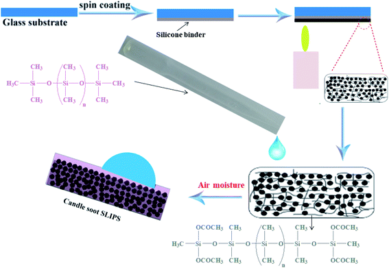 | ||
| Fig. 1 Schematic represents the fabrication of candle soot slippery liquid infused porous surface (CS + SLIPS). | ||
2.3 Characterization of surface properties
The roughness and topography of the fabricated surface were measured by operating AFM (Agilent 5500) with tap mode and SEM (Hitachi SU-8010) with 3.0 kV energy of beam and 10.0 mm working distance respectively. The average value of contact angle, sliding angle, and the contact angle hysteresis (sessile drop, needle in method) of various liquid droplet (10 μL) with different surface tension was determined by Dataphysics OCA 50 California USA. The liquid-repellent property was determined by applying water, glycerol, ethylene glycol, propylene glycol, poly ethylene glycol, dimethylsulfoxide (DMSO), formamide (DMF), blood, milk and, coffee respectively. The surface tension of these liquids was also measured with the help of by the pendant drop method. The surface area and porosity of soot particles were determined by using the micrometric instrument ASAP 2020. The nitrogen adsorption was performed at −196 °C with 10 second equilibration intervals. Data were collected from vacuum to one atmospheric pressure.2.4 Icephobic performance
The icephobicity of the fabricated surfaces was determined with the help of crystallization delay, freezing delay of the water droplet, and ice adhesion strength. The crystallization point of water was determined on three samples with the help of a DSC (TAQ 200). For this purpose, three aluminium pans were obtained, one is taken as blank (hydrophilic), second is coated with RTV + Soot particles (superhydrophobic surface), third is coated with RTV + Soot particles + dimethyl silicone oil (slippery surface). 3 mg water (deionized) is added in each pan. The prepared samples were placed at the same time in the plate of DSC TQ200, temperature was adjusted with cooling rate 5 °C per minute to −70 °C, then isothermal for 3.00 min. The freezing delay of water was recorded on hydrophilic glass, superhydrophobic (CS + RTV-1) surface and slippery (CS-SLIPS) surface with the help of a goniometer. For this purpose, the prepared surfaces were placed on a Peltier cooler and maintained their temperature at −20 ± 2 °C. The temperature of the environment was 22.0 ± 5 °C with relative humidity (60 ± 3%). We calculated the freezing delay of water (7 μL droplet) by observing the appearance of the water droplet was noted very carefully until a sharp solid peak was appeared in the water droplet. The same experiment was repeated five times to obtain its mean value.The ice adhesion strength was calculated on hydrophilic glass, superhydrophobic (CS + RTV-1) surface and slippery (CS-SLIPS) surface. Finally, the ice adhesion values were calculated on the slippery soot surface after its certain stability tests. For this purpose, the prepared samples (CS-SLIPS) having (1.5 mL) deionized water was dropped in a plastic cuvette having dimensions (10 mm × 10 mm × 45 mm). The samples were turned down and put in the refrigerator at −10 °C for 4 h. Before measuring the ice adhesion strength, the samples were put into the cooling chamber at −20 °C for 8 minutes for their stabilization. The dynamometer (NK-50) was used to measure the ice adhesion strength.
2.5 Mechanical stability tests
The stability of the fabricated candle soot slippery surface (CS-SLIPS) was determined with the help of icing/deicing cycles, frosting/defrosting cycles, super-cold water-impact, liquid nitrogen/water cycles, dipping under ice and acidic/basic water flow. The frosting/defrosting cycles test was performed on the fabricated slippery soot surface at −20 °C, −90 °C and under liquid nitrogen temperature (−150 °C). The icing/deicing cycles test was performed 100 times on the fabricated slippery soot surface at −20 °C. The super-cold water-impact test was performed by dropping 800 mL beaker of super-cold water on the slippery candle soot surface (CS-SLIPS). The slippery candle soot surface was also dipped under the ice for 2 months. The thermal stability of the slippery soot surface was measured by putting the fabricated glass slide in an oven at 60 °C for 2 months. The water contact angle, sliding angle, ice adhesion value and mass loss of the lubricants (BS 224S (Sartorius, Beijing) analytical balance) were measured on daily basis during the period of 2 months. The stability of the candle soot slippery surface was also measured by putting the fabricated glass slide in a beaker filled with 200 mL of deionized water, acidic (pH = 4) and basic water (pH = 12) with gentle flow of water for 9 days. The water contact angle, sliding angle, ice adhesion value and mass loss of the lubricants (BS 224S (Sartorius, Beijing) analytical balance) were measured on daily basis during the period of 9 days. The mass ratio was calculated with the help of the following formula Mratio = Mafter/Mbefore. The developed surface was also pressed with finger, adhesive tape (Scotch-600 + 200 g weight) and, cuts were applied with the help of knife in order to determine its stability after physical damages.3. Results and discussions
3.1 Design principle of SLIPSs
Before laying to the fabrication method, we discuss the design principle of SLIPS (slippery liquid infused porous surfaces). The stable slippery surface must fulfill the following criteria (i) lubricating oil and probe liquid must be immiscible; (ii) lubricant must be wet and wick into the solid substrate (surface energy of solid substrate must be higher than the surface tension of lubricating oil, ought to mismatch the probe liquid; if intrinsic surface energy of solid substrate does not match with lubricating oil, the chemical composition of solid substrate could be modified). (iii) The solid substrate must have a higher affinity for the lubricating oil over the probe liquid. (iv) The solid substrate should preferably have nanoscale roughness in order to provide the large surface area for the retention and the strong adhesion of lubricating oil.18,46 Our slippery soot coating follows all the principles as conspicuously evident in the Video S1, ESI.†3.2 Fabrication and surface properties of slippery soot surface
Although the soot particles show great water repellency, they do not have any physiochemical interaction with the substrate which confirms its poor adhesive property.47 To address this issue, a silicone binder (RTV-1, PDMS component) is used to develop its adhesive behavior with the substrate. The RTV-1 (room temperature vulcanizable) is used as a low modulus hydrophobic binder. The base material RTV-1 is viscoelastic, resistant to high temperature, readily curable and non-deformable.The binder RTV-1 was spin-coated (4000 rpm, thickness 90 μm) on the substrate. Then, the RTV-1 coated substrate was brought above the candle flame and we selected the topmost part of the candle flame (3.2 cm above the wick of candle, supplementary Fig. S1†) in order to deposit the soot particles with smaller size ≤20 nm. The soot deposition continued for one minute with constant to and fro motion of RTV-1 coated substrate in order to get a uniform layer of soot particles. RTV-1 coated substrate turned black with sustainable thin film of rubber owing to it's non-deformable and resistant to high temperature as shown in Fig. 1 and S2, ESI.† Fig. S3a, ESI,† shows the porous morphology and fragile structure of the soot particles without binder (RTV-1). The soot particles deposited into the binder RTV-1 are shown in SEM image of Fig. S3b, ESI.† The collected spherical soot particles have average size of 20 nm. The results of AFM show that the soot deposited substrate has average root mean square roughness (Rrms) of 168 nm as shown in Fig. S3c and d, ESI.† The prepared soot coated superhydrophobic surface was covered by applying the droplets of dimethyl silicone oil. The silicone oil gets completely penetrated into the soot coated substrate due to its porosity, suitable surface energy, and nanoscale roughness (cause increase in surface area). The porosity and nanoscale roughness of soot particles (Fig. 2) enhances the adhesion and immobilization of lubricant due to the capillarity.48
 | ||
| Fig. 2 Schematic shows the fabrication of stable SLIPS due to the capillarity of porous soot particles. | ||
The nitrogen adsorption–desorption isotherms in Fig. S5† shows the surface area up to 156.66 m2 g−1 and the total pore volume up to 0.5144 cm3 g−1 with 13.8 nm pore diameter. In addition, the magnified SEM images and other structural parameters of the porous soot particles have also been shown in Fig. S4 and Table S1† respectively. Thus, these small size interconnected pores enhanced the complete spreading, and firmly holding of lubricant for the good slippery behavior of soot particles.
In addition, the adhesive base material RTV-1 silicone and the lubricant silicone oil show strong affinity with each other due to their identical chemical composition. The lubricant was applied only for 15 minutes, then the substrate was stood vertically to remove the excess lubricating oil. Finally, the substrate was allowed to stand until its complete dryness and curing of binder RTV-1 at room temperature. The soot coated RTV-1 network swelled and proved to be a good reservoir for the retention of silicon oil as shown in Fig. 3. Further chemistry about the RTV-1 binder and its curing at room temperature has been discussed in Scheme S1, ESI.†
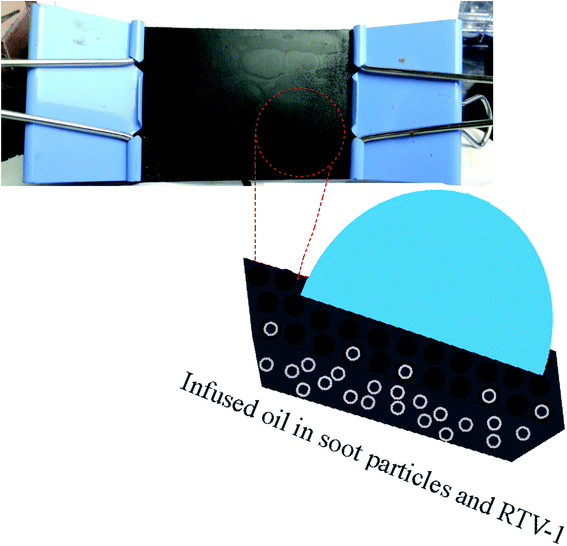 | ||
| Fig. 3 Schematic shows the candle soot slippery surface (CS-SLIPS) as a good reservoir and lock in place of silicone oil. | ||
The smooth nature of the developed slippery surface of soot is manifest in Fig. 4 by AFM and SEM results. The interaction of water with superhydrophobic and slippery surfaces of soot particles can be seen in ESI Video S2.† It shows that the position of trapped air in superhydrophobic surface (shiny silver mirror) has been replaced with lubricating oil to make it slippery in nature.
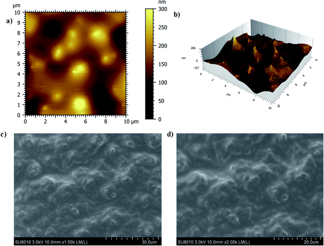 | ||
| Fig. 4 (a) 2-D AFM image of slippery soot surface (b) 3-D AFM image of slippery soot surface (c) SEM image of slippery soot surface (d) Magnified SEM image of slippery soot surface. | ||
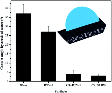
The wettability results of the uncoated (hydrophilic) and coated (hydrophobic to slippery) surfaces are shown in ESI Fig. S6.† The contact angle hysteresis (CAH) of water droplet (10 μL) was also measured on the prepared samples as available in Fig. 5. The low CAH = 3° value of slippery soot surface also indicates its smooth nature without the pinning points.
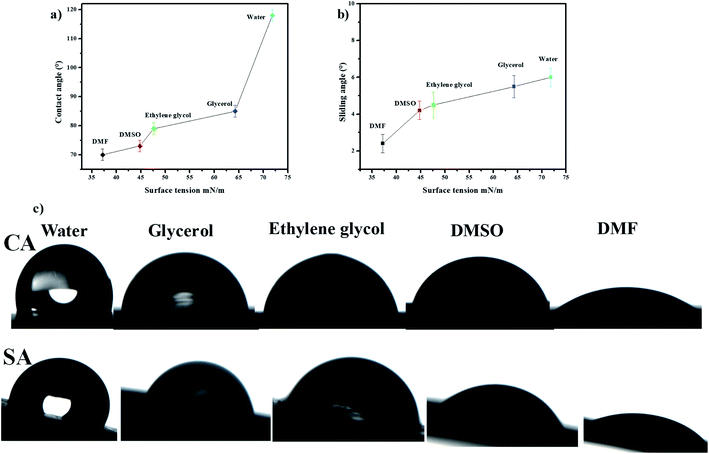
The slippery performance of the prepared surface is also determined with the help of sliding angles (SA) and contact angles (CA) of various liquid droplets having different surface tensions. The Fig. 6 shows that the value of contact angles of different liquid droplets rise with the increase of surface tension for 10 μL droplet volume. The contact angles of 10 μL droplets of formamide, dimethylsulfoxide (DMSO), ethylene glycol, glycerol, and water are 70 ± 2.0°, 73 ± 2°, 79 ± 2°, 85 ± 2°, and 118 ± 2° respectively. The sliding angles increase with the rise of surface tensions of various liquid droplets for 10 μL droplet volume. The sliding angles of 10 μL droplet volume of formamide (DMF), dimethylsulfoxide (DMSO), ethylene glycol, glycerol, and water are 2.4 ± 0.5°, 4.2 ± 0.5°, 4.5 ± 0.7°, 5.5 ± 0.6°, and 6 ± 0.5°, respectively as shown in Fig. 6b. Fig. 6c shows the photos of contact angles and sliding angles of various liquid droplets for 10 μL droplet volume on the soot slippery surface. These photos clearly show difference of wetting of behavior of various liquid droplets having different surface tension.
The omniphobic nature of soot slippery surface provide a straightforward solution for blood repellency, resistance to fouling (Fig. 7) and repellency of liquids with different surface tension. The slippery behavior of the above mentioned liquids with different surface tensions including coffee, milk and blood can be shown in the Video S3.†
 | ||
| Fig. 7 Photos (a and b) represent the blood repellency and its contact angle with soot slippery surface. | ||
3.3 Delay in freezing point on candle soot slippery surface
The delay in the crystallization of water droplets was determined through differential scanning calorimeter (DSC, Q200 system, TA instruments) analysis by decreasing the temperature incrementally and the complete freezing phenomenon of a single water droplet was observed with the help of goniometer (CAM 200 OCA) at −20 °C.42,49 The DSC results reveal that the candle soot slippery (CS-SLIPS) crucible shows small heat flow (released due to water crystallization) as compare to superhydrophobic (CS + RTV-1) and blank hydrophilic crucible. The small heat flow is attributed to the insulating thin layer of lubricant oil. The ultra-smooth interface of oil-infused soot particles lowers the crystallization rate of water droplet due to the reduced ice nucleation sites as compared to the superhydrophobic surface. Since the blank crucible is hydrophilic in nature and has more contact area with water droplet, therefore the water droplet of hydrophilic crucible shows large heat flow (171 W g−1) and crystalizes at −9.9 °C (high temperature) as compared to superhydrophobic (CS + RTV-1, −12.8 °C) and slippery oil-infused candle soot surface (CS-SLIPS, −13.3 °C) as shown in Fig. 8. Thanks to the reduced ice nucleation sites of oil-infused soot particles and their slippery property for delaying the crystallization of water (3.4 °C).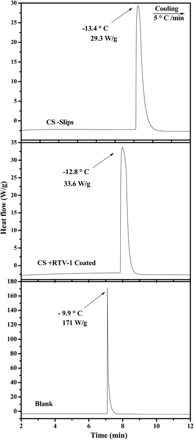 | ||
| Fig. 8 DSC curves of super-cooled water droplet on blank crucible (hydrophilic), crucibles with candle soot (superhydrophobic) and crucibles with candle soot slips (slippery). | ||
The complete freezing phenomenon of a single water droplet (7 μL) was also observed on hydrophilic (glass), candle soot deposited glass (superhydrophobic) and slippery oil-infused soot surface at −20 ± 2 °C. The transparent center of water droplet gets disappeared and a sharp peak of ice appeared after the completion of freezing process. The freezing delay of water droplet on the prepared samples was observed in this order: slippery surface (CS-SLIPS) > superhydrophobic surface (CS + RTV-1) > hydrophilic surface (glass). The slippery surface of soot particles (CS-SLIPS) showed six times more freezing delay of water as compared to hydrophilic glass as shown in Fig. 9. The delay in freezing point and crystallization of water affirm that the slippery surface of soot particles prevents the ice formation by removing the water droplet before its freezing. The freezing delay of water droplet is credited to the slippery interface due to lack of pinning points and heterogeneities. The candle soot slippery interface is suitable for homogenous nucleation of water according to the classical nucleation theory.50 Eqn (1) and (2) represents the relation between the homogenous nucleation barrier (ΔGhomo) and heterogeneous nucleation barrier (ΔGHeter). The value of their cofactor S(θ) was determined by using the following eqn (3) which depends on contact angle θ.
 | (1) |
 | (2) |
 | (3) |
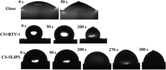 | ||
| Fig. 9 Photographs show the delay in the freezing process of water droplet (7 μL) on hydrophilic glass, superhydrophobic soot surface (CS + RTV-1) and slippery soot surface (CS-SLIPS). | ||
In short, when the temperature of the soot coated superhydrophobic surface decreases, the trapped air (Cassie–Baxter state) in between the soot particles and the water droplet is removed with the passage of time then soot particles provide nucleation site for the water molecules to form a stable ice nucleus in short time. But in case of slippery liquid infused surface SLIPS, the possible nucleation sites of soot particles are reduced by applying silicone oil.28 The solid–liquid interface is converted into liquid–liquid interface (SLIPS) which helps to slow the homogenous nucleation as compared to superhydrophobic surface. Thus, SLIPS surface of soot particles provides a chemically homogeneous interface and drastically reduces the possible nucleation sites which results delay in freezing point of water.
3.4 Ice adhesion strength
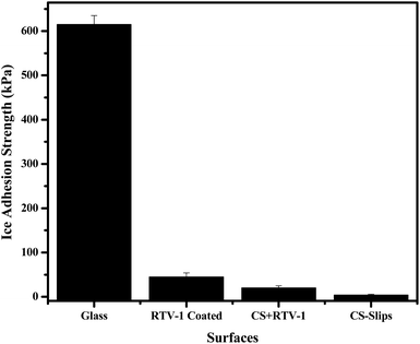
The icephobic surfaces show ice adhesion τice < 100 kPa.43,45 In our case, the soot slippery surface showed extremely low ice adhesion (3 ± 1 kPa) as compared to the superhydrophobic (20 ± 5 kPa) and hydrophilic glass (615 ± 20 kPa) as shown in Fig. 10. A real icephobic surface can also remove the ice under gravity action, small vibration and wind forces. We have performed different tests at different temperatures (25 °C to −90 °C) and observed the ice fall under the action of gravity, vibration, air pressure, and small force of tweezers. For this purpose, the ice pieces of different sizes were made on the slippery soot surface then their fall was observed under the action of gravity. This shows that a large and a small piece of ice can be easily removed from the developed slippery surface as evident in the ESI Video S4.† We also observed the ice removal at −20 °C on slippery soot surface due to wind force as shown in ESI Video S5.† This test shows that the ice can be easily removed from the slippery soot surface at low temperature. Finally, we observed the ice removal with the help of small force (tweezers) at different temperatures (25 °C to −90 °C). This test also confirms the easy removal of ice from the slippery soot surface even at −90 °C as shown in the ESI Video S6.†3.5 Stability of slippery soot surface
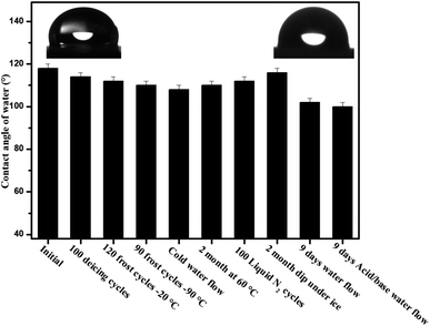
The poor stability of slippery surfaces is a big problem that hinders its use for industrial applications. The leakage and evaporation of lubricant can destroy its slippery and icephobic behavior. To address this issue, we have developed a long-life slippery surface of soot particles with the durable binder (RTV-1, cured at room temperature and swelled in the presence of lubricant). The capillarity effect of porous soot particles and chemical affinity of the lubricant with base material RTV-1 (binder) played an important role in the longevity of the surface. In order to determine the stability of the developed slippery surface tests viz. icing/deicing cycles; frosting/defrosting cycles; super-cold water-impact; liquid nitrogen/water cycles; dip under ice; thermal stability at 60 °C and acidic/basic water flow were performed. The slippery soot surface maintained its slippery property (SA, 10 ± 1°) with ice adhesion value (3 ± 0.3 kPa) after 100 icings/deicing and 120 frostings/defrosting cycles at −20 °C as shown in Fig. 12 and 13. In order to convince the readers about this novel surface, 90 times frosting/defrosting test was performed at −90 °C. At the end, little increase in sliding angle 15 ± 1° (decrease in contact angle, 110 ± 2°, Fig. 14) and increase in ice adhesion value (3.5 ± 0.3 kPa) was observed as compared to initial state values of the slippery soot surface as shown in the Fig. 12 and 13 respectively. | ||
| Fig. 11 Candle soot slips (CS-SLIPS) maintain its slippery behavior after 2 months dip under the ice. | ||
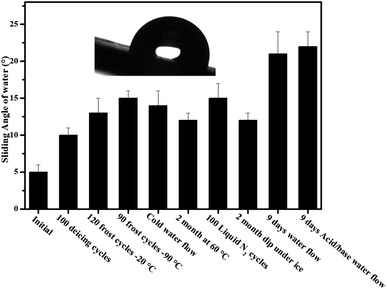 | ||
| Fig. 12 Schematic shows the sliding angle of candle soot slippery surface (CS-SLIPS) after different stability tests. | ||
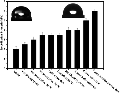 | ||
| Fig. 13 Schematic shows the ice adhesion strength of candle soot slippery surface (CS-SLIPS) after different stability tests. | ||
We also determined the stability of slippery soot surface under drastic conditions (∼−150 °C substrate temperature) 100 liquid nitrogen/water cycles. The developed slippery surface was put into the liquid nitrogen for 50 seconds then quickly dipped it into the water in order to make a thin ice layer. A gentle vibration or a weak shear force is enough to remove the thin layer of ice before its melting as shown in ESI Video S7.† Finally, increase in sliding angle 15 ± 2° (decrease in contact angle 112 ± 2° Fig. 14) and increase in ice adhesion value (4 ± 0.3 kPa) was observed as compared to initial state values of the slippery soot surface as shown in Fig. 12 and 13 respectively. The slippery behavior of super-cold water (−10 °C) was also observed on the developed slippery soot surface. First, we dropped small super-cold water droplets then 800 mL beaker of super-cold water with certain height was dropped on to the slippery soot surface as shown in ESI Video S8.† This test shows that the surface maintains its slippery and hydrophobic property even after the impact of super-cold water and little increase in sliding angle 14 ± 2° (decrease in contact angle 108 ± 2°, Fig. 14) and increase in ice adhesion value (3.5 ± 0.2 kPa) was observed as compared to initial state value of the slippery soot surface as shown in Fig. 12 and 13 respectively.
The stability of developed surface was observed by dipping it completely under the ice for 2 months at −10 °C as shown in Fig. 11. After 2 months, the surface was placed at room temperature for some time then the thick layer of ice was allowed to fall off under the gravity action shown in ESI Video S9† and little increase in sliding angle 12 ± 1° (decrease in contact angle 116 ± 2° Fig. 14) and increase in ice adhesion value (4 ± 0.2 kPa) was noted after 2 months as compared to initial state value of the slippery soot surface as shown in Fig. 12 and 13 respectively.
Similarly the thermal stability of the developed surface was observed by putting it in an oven at 60° for 2 months and increase in sliding angle 12 ± 1° (decrease in contact angle 156° Fig. 14) and increase in ice adhesion value (3.5 ± 0.2 kPa) was noted as compared to initial state value of the slippery soot surface as shown in the Fig. 12 and 13 respectively.
In order to observe the stability of the developed surface in flowing water, the surface was dipped in three different beakers (200 mL pure water, mild acidic water, mild basic water) for 9 days with gentle water flow and the water was changed after every 24 hours respectively. The contact angle, sliding angle and mass loss was noted every time. Finally, the change in a mass loss was negligible (Fig. S7, ESI†) due to the very strong affinity of lubricant with soot particles and curable binder RTV-1. The increase in sliding angle 21 ± 3° (decrease in contact angle 102 ± 2°, Fig. 14) and increase in ice adhesion value (5 ± 0.2 kPa) was observed as compared to initial state value of the slippery soot surface as shown in Fig. 12 and 13 respectively. The increase in sliding angle after 9 days water flow in mild acidic/basic conditions indicates that the depletion of lubricating layer (dimethyl silicone oil) starts. If the same experiment is performed for longer periods under higher water stirring, then the complete loss of lubricating layer may occur resulting the loss of slippery property. This problem can be solved by increasing the thickness of acid/base resistant RTV silicone rubber (binder, lubricant reservoir) as well as by using high viscosity and cross-linking silicone lubricant. Generally slippery liquid infused surfaces have contact angle of water above 100°. In our case the developed slippery surface of candle soot maintained its contact angle above 100° after different tests performed in harsh conditions as shown in Fig. 14. The reason behind this is the strong affinity of silicone oil with low energy soot particles.
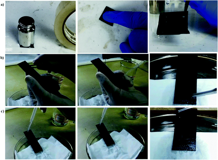
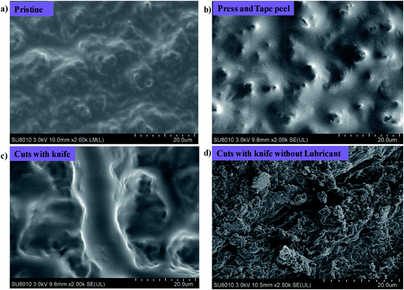
We know that the liquid repellent property of the surfaces is destroyed in harsh conditions and do not show damage resistant slippery property. But in our case, the fluidic nature of low viscosity silicone oil and its strong affinity with the porous soot particles along with RTV binder helps to make a damage resistant slippery surface. The possible mechanism of the developed damage resistant slippery surface is the replenishing of the lubricating layer after physical damages. The lubricant in the porous soot and RTV rubber can flow freely towards the damaged area due to the surface-energy-driven capillary action,7 and refills the physical voids spontaneously. Thus we can say that the firmly locked silicone oil into the nanopores of soot particles forms a defect-free lubricating interface that eliminates the pinning of liquid applied to its surface. This leads to form a robust damage resistant slippery surface.54 The Fig. 15 shows the stability of the slippery soot surface after tape peel with 200 g weight, pressing with finger, and applying many cuts in different directions on the surface. The SEM images of the slippery soot surface before and after applying physical damages have been shown in the Fig. 16. In addition, we used the polarizing microscope (NikON, ECLIPSE E600W, Japan) to observe the clear difference in the slippery soot surface before and after applying physical damages. The resulting images have been shown in the ESI S8 and S9.† The stability of the developed damage resistant slippery surface can be clearly seen in Videos S10 and S11.† The slippery surface of candle soot maintained its stability after different tests performed in harsh conditions as shown at the end of ESI.† Moreover, the stability can also be increased by increasing the thickness of the coating as well as using high viscosity and cross-linking silicone oil.
4. Conclusion
In conclusion, we have demonstrated a new approach for fabricating a simple, low cost, scalable and environmentally friendly SLIPS surface which relies on silicon-oil-infused nanostructure of porous soot particles deposited on binder RTV-1. The developed surface shows repellency to several liquids with different surface tensions including blood and damage resistant slippery property due to strong affinity of silicone oil with soot particles along with RTV-1 silicone binder. The stable and defect-free lubricating interface shows delay in freezing point along with ultra-low ice adhesion strength (2 kPa) and maintains it below 7 kPa after harsh environmental conditions. The slippery soot surface also exhibited low ice adhesion strength at sub-zero temperature. We believe this new development is also suitable for large scale applications such as anti-fouling and drag reduction.Conflicts of interest
The authors declare no competing financial interest.Acknowledgements
The authors would like to gratefully acknowledge the National Natural Science Foundation of China (NSFC) for Award No. 21878267, 21576236 and 21676248 for supporting this research.References
- H. Liu, Y. Wang, J. Huang, Z. Chen, G. Chen and Y. Lai, Adv. Funct. Mater., 2018, 28, 1707415 CrossRef.
- M. Liu, S. Wang and L. Jiang, Nat. Rev. Mater., 2017, 2, 17036 CrossRef CAS.
- Y. C. Jung and B. Bhushan, Langmuir, 2009, 25, 9208–9218 CrossRef CAS PubMed.
- X. Meng, Z. Wang, L. Wang, L. Heng and L. Jiang, J. Mater. Chem. A, 2018, 6, 16355–16360 RSC.
- S. Yizhou, W. Guanyu, T. Jie, Z. Chunling, L. Senyun, J. Mingming, X. Yuehan and C. Zhong, Adv. Mater. Interfaces, 2017, 4, 1700836 CrossRef.
- Y. Shen, J. Tao, G. Wang, C. Zhu, H. Chen, M. Jin and Y. Xie, J. Phys. Chem. C, 2018, 122, 7312–7320 CrossRef CAS.
- T.-S. Wong, S. H. Kang, S. K. Y. Tang, E. J. Smythe, B. D. Hatton, A. Grinthal and J. Aizenberg, Nature, 2011, 477, 443–447 CrossRef CAS PubMed.
- J. D. Smith, R. Dhiman, S. Anand, E. Reza-Garduno, R. E. Cohen, G. H. McKinley and K. K. Varanasi, Soft Matter, 2013, 9, 1772–1780 RSC.
- Y. Jiao, X. Lv, Y. Zhang, C. Li, J. Li, H. Wu, Y. Xiao, S. Wu, Y. Hu, D. Wu and J. Chu, Nanoscale, 2019, 11, 1370–1378 RSC.
- M. Zhang, J. Yu, R. Chen, Q. Liu, J. Liu, D. Song, P. Liu, L. Gao and J. Wang, J. Alloys Compd., 2019, 803, 51–60 CrossRef CAS.
- Y. Fu, J. Jiang, Q. Zhang, X. Zhan and F. Chen, J. Mater. Chem. A, 2016, 5, 275–284 RSC.
- Z. Li and Z. Guo, Nanoscale, 2019, 11, 22636–22663 RSC.
- M. I. Jamil, A. Ali, F. Haq, Q. Zhang, X. Zhan and F. Chen, Langmuir, 2018, 34, 15425–15444 CrossRef CAS PubMed.
- Z. Guo and F. Yang, Surfaces and Interfaces of Biomimetic Superhydrophobic Materials, John Wiley & Sons, 2017 Search PubMed.
- S. Wang, K. Liu, X. Yao and L. Jiang, Chem. Rev., 2015, 115, 8230–8293 CrossRef CAS PubMed.
- M. I. Jamil, X. Zhan, F. Chen, D. Cheng and Q. Zhang, ACS Appl. Mater. Interfaces, 2019, 11, 31532–31542 CrossRef CAS PubMed.
- X. Jing and Z. Guo, Nanoscale, 2019, 11, 8870–8881 RSC.
- M. Villegas, Y. Zhang, N. Abu Jarad, L. Soleymani and T. F. Didar, ACS Nano, 2019, 13, 8517–8536 CrossRef CAS PubMed.
- G. Wang and Z. Guo, Nanoscale, 2019, 11, 22615–22635 RSC.
- P. Tourkine, M. Le Merrer and D. Quere, Langmuir, 2009, 25, 7214–7216 CrossRef CAS PubMed.
- S. Jung, M. K. Tiwari, N. V. Doan and D. Poulikakos, Nat. Commun., 2012, 3, 615 CrossRef PubMed.
- T. Maitra, M. K. Tiwari, C. Antonini, P. Schoch, S. Jung, P. Eberle and D. Poulikakos, Nano Lett., 2014, 14, 172–182 CrossRef CAS PubMed.
- L. Mishchenko, B. Hatton, V. Bahadur, J. A. Taylor, T. Krupenkin and J. Aizenberg, ACS Nano, 2010, 4, 7699–7707 CrossRef CAS PubMed.
- K. K. Varanasi, T. Deng, J. D. Smith, M. Hsu and N. Bhate, Appl. Phys. Lett., 2010, 97, 234102 CrossRef.
- S. A. Kulinich, S. Farhadi, K. Nose and X. W. Du, Langmuir, 2011, 27, 25–29 CrossRef CAS PubMed.
- N. H. Fletcher, J. Chem. Phys., 1958, 29, 572–576 CrossRef CAS.
- M. Qian and J. Ma, J. Chem. Phys., 2009, 130, 214709 CrossRef PubMed.
- P. W. Wilson, W. Lu, H. Xu, P. Kim, M. J. Kreder, J. Alvarenga and J. Aizenberg, Phys. Chem. Chem. Phys., 2013, 15, 581–585 RSC.
- P. Kim, T.-S. Wong, J. Alvarenga, M. J. Kreder, W. E. Adorno-Martinez and J. Aizenberg, ACS Nano, 2012, 6, 6569–6577 CrossRef CAS PubMed.
- D. Daniel, J. V. I. Timonen, R. Li, S. J. Velling, M. J. Kreder, A. Tetreault and J. Aizenberg, Phys. Rev. Lett., 2018, 120, 244503 CrossRef CAS PubMed.
- J. Li, E. Ueda, D. Paulssen and P. A. Levkin, Adv. Funct. Mater., 2019, 29, 1802317 CrossRef.
- K. Rykaczewski, S. Anand, S. B. Subramanyam and K. K. Varanasi, Langmuir, 2013, 29, 5230–5238 CrossRef CAS PubMed.
- M. Kreder, A. Tetreault, Z. Cao, B. Lemaire, J. V. I. Timonen, J. Aizenberg and D. Daniel, Phys. Rev., 2018, 031053 CAS.
- J. Chen, Z. Luo, Q. Fan, J. Lv and J. Wang, Small, 2014, 10, 4693–4699 CrossRef CAS PubMed.
- J. Chen, R. Dou, D. Cui, Q. Zhang, Y. Zhang, F. Xu, X. Zhou, J. Wang, Y. Song and L. Jiang, ACS Appl. Mater. Interfaces, 2013, 5, 4026–4030 CrossRef CAS PubMed.
- D. L. Beemer, W. Wang and A. K. Kota, J. Mater. Chem. A, 2016, 4, 18253–18258 RSC.
- Z. He, S. Xiao, H. Gao, J. He and Z. Zhang, Soft Matter, 2017, 13, 6562–6568 RSC.
- P. Irajizad, A. Al-Bayati, B. Eslami, T. Shafquat, M. Nazari, P. Jafari, V. Kashyap, A. Masoudi, D. Araya and H. Ghasemi, Mater. Horiz., 2019, 6, 758–766 RSC.
- Y. Wang, X. Yao, S. Wu, Q. Li, J. Lv, J. Wang and L. Jiang, Adv. Mater., 2017, 29, 1700865 CrossRef PubMed.
- J. Lv, X. Yao, Y. Zheng, J. Wang and L. Jiang, Adv. Mater., 2017, 29, 1703032 CrossRef PubMed.
- Y. Wang, X. Yao, J. Chen, Z. He, J. Liu, Q. Li, J. Wang and L. Jiang, Sci. China Mater., 2015, 58, 559–565 CrossRef CAS.
- Y. Yu, B. Jin, M. I. Jamil, D.-G. Cheng, Q. Zhang, X. Zhan and F. Chen, ACS Appl. Mater. Interfaces, 2019, 11, 12838–12845 CrossRef CAS PubMed.
- K. Golovin, S. P. R. Kobaku, D. H. Lee, E. T. DiLoreto, J. M. Mabry and A. Tuteja, Sci. Adv., 2016, 2, 1–12 Search PubMed.
- K. Golovin and A. Tuteja, Sci. Adv., 2017, 3, 1–9 Search PubMed.
- K. Golovin, A. Dhyani, M. Thouless and A. Tuteja, Science, 2019, 364, 371–375 CrossRef CAS PubMed.
- Z. Ashrafi, L. Lucia and W. Krause, ACS Appl. Mater. Interfaces, 2019, 11, 21275–21293 CrossRef CAS PubMed.
- A. E. Kandjani, Y. M. Sabri, M. R. Field, V. E. Coyle, R. Smith and S. K. Bhargava, Chem. Mater., 2016, 28, 7919–7927 CrossRef CAS.
- A. Milionis, I. Bayer and E. Loth, Int. Mater. Rev., 2016, 61, 101–126 CrossRef CAS.
- X. Zhan, Y. Yan, Q. Zhang and F. Chen, J. Mater. Chem. A, 2014, 2, 9390–9399 RSC.
- Z. Zhang and X.-Y. Liu, Chem. Soc. Rev., 2018, 47, 7116–7139 RSC.
- P. Irajizad, M. Hasnain, N. Farokhnia, S. M. Sajadi and H. Ghasemi, Nat. Commun., 2016, 7, 13395 CrossRef CAS PubMed.
- T. M. Schutzius, S. Jung, T. Maitra, P. Eberle, C. Antonini, C. Stamatopoulos and D. Poulikakos, Langmuir, 2015, 31, 4807–4821 CrossRef CAS PubMed.
- M. J. Kreder, J. Alvarenga, P. Kim and J. Aizenberg, Nat. Rev. Mater., 2016, 1, 15003 CrossRef CAS.
- N. Vogel, R. A. Belisle, B. Hatton, T.-S. Wong and J. Aizenberg, Nat. Commun., 2013, 4, 2176 CrossRef PubMed.
Footnote |
| † Electronic supplementary information (ESI) available. See DOI: 10.1039/d0ra01786h |
| This journal is © The Royal Society of Chemistry 2020 |

