 Open Access Article
A template free protocol for fabrication of a Ni(II)-loaded magnetically separable nanoreactor scaffold for confined synthesis of unsymmetrical diaryl sulfides in water†
Gunjan Arora a,
Manavi Yadav
 ab,
Rashmi Gaur
 a,
Radhika Gupta
 a,
Pooja Rana
 a,
Priya Yadav
 ab and
Rakesh Kumar Sharma
 *a
*a
aGreen Chemistry Network Centre, Department of Chemistry, University of Delhi, Delhi-110007, India. E-mail: rksharmagreenchem@hotmail.com
bDepartment of Chemistry, Hindu College, University of Delhi, Delhi-110007, India
First published on 21st May 2020
Abstract
In the present report, an environmentally benign magnetically recoverable nickel(II)-based nanoreactor as a heterogeneous catalyst has been developed via a template free approach. The catalytic performance of the synthesized catalyst is assessed in the confined oxidative coupling of arenethiols with arylhydrazines to form unsymmetrical diaryl sulfides under aerobic conditions. The salient features of our protocol include oxidant- and ligand-free conditions, use of water as a green solvent, room temperature and formation of nitrogen and water as the only by-products. Moreover, a broad range of functional groups are tolerated well and provide the corresponding diaryl sulfides in moderate to good yields. Moreover, the heterogeneous nature of the catalyst permits facile magnetic recovery and reusability for up to seven runs, making the present protocol highly desirable from industrial and environmental standpoints.
Introduction
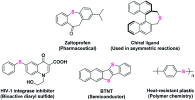
Aromatic sulfides represent an important class of organosulfur compounds that have a wide utility in various fields such as pharmaceutical chemistry, materials sciences and synthetic and polymer chemistry (Scheme 1).1–5 The extensive presence of C–S bonds in several drug molecules used in many targeted diseases, such as inflammation, HIV, diabetes, asthma, cancer, mood disorders, and Parkinson's and Alzheimer's diseases, validates the importance of C–S bond-forming reactions.6–11Over the last few decades, transition metal catalyzed oxidative cross-coupling reactions have emerged as a powerful and straightforward tool for the construction of carbon–carbon and carbon–heteroatom bonds.12–14 Eventually, numerous catalytic systems have been developed for the synthesis of diaryl sulfides via the transition metal mediated formation of C(sp2)–S bond. For instance, Shi et al. have reported Ni(OAc)2 and N-heterocyclic carbene catalyzed cross-coupling reaction of aryl halides with various aliphatic and aromatic thiols.15 In another study a magnetically recoverable and reusable CuFe2O4 nanocatalyst was fabricated that facilitates the formation of aryl–sulfur bond between aryl halides and thiols/disulfides.16 Recently, a rhodium-catalyzed approach has been introduced where deborylthiolation of borylarenes using thiosulfonates was done to synthesize diaryl sulfides.17 A report by Fu and co-workers described visible-light photoredox arylation of thiols with aryl halides at room temperature using [fac-Ir(ppy)3] as catalyst.18 However, these approaches suffer from various disadvantages such as use of high temperature, longer reaction time, toxic ligands, reagents and/or solvents. Moreover, most of these approaches are based on coupling of different electrophiles such as aryl halides and triflates with arenethiols. Besides, organic halides are expensive (organic bromides and iodides), less reactive (organic chlorides) and toxic. Organic triflates on the other hand are unstable and produce toxic triflic acid as a by-product. Therefore, there is still a need to expand the scope of electrophilic coupling partners in transition metal catalyzed C–S bond forming reactions.
Arylhydrazines have been recognized as environmentally benign arylating agents for oxidative cross-coupling reactions as the only associated by-products are nitrogen gas and water during C–N bond cleavage.19,20 Zhao and co-workers reported an efficient catalytic system, Pd(OAc)2-PCy3-Na2CO3, for the oxidative cross coupling of arylhydrazines with arenethiols in toluene at 100 °C to afford diaryl sulfides in good to high yields.21 Although, the protocol has highly improved the choice of electrophilic coupling partner, however, high temperature and use of non-green solvent limits its large-scale applicability. Besides, the system is homogeneous in nature, which makes the product purification difficult. Very recently, Yuan and group disclosed a surfactant-type catalyst that along with PEG-functionalized amphiphilic nitrogen ligand at 100 °C showed admirable efficiency and selectivity for oxidative coupling of hydrazines with thiols in water.22 Moreover, the mother liquor was catalytically active after five cycles. Nevertheless, the use of high temperature and external ligand make the protocol less environmentally benign. Therefore, the development of other recoverable and reusable catalytic systems which operate under room temperature and utilize green solvents is a highly desirable goal.
In recent years, use of hierarchical core–shell architectures as heterogeneous support is considered a promising way to immobilize catalytically active species due to the unique combination of functional and structural characteristics.23–25 Some outstanding features of these materials are high surface area, large cavity volume, low density, excellent loading capacities and ease of surface modification.26–30 Physical and chemical properties of these hollow structures can be easily tuned and controlled by altering chemical compositions and relative dimensions of core and shells. Therefore, hollow nanocomposites, especially those comprising of magnetic core/shell and functional shells, find possible applications as efficient nanocatalysts due to ease of separation and recycling.
As we are working on designing and synthesis of sustainable catalysts,31–42 we herein report the synthesis of nickel-based hollow magnetic catalyst. The synthesized composite is comprised of nano-scaled cavity and double shells; inner magnetite shell that allows easy magnetic separation and external carbon layer that imparts high stability and protects the inner shell and metal species from external environment. Most importantly, the confined nano-cavity inside the composite provides an isolated space for reactions to occur, so, it acts as a nanoreactor. Further, the catalytic activity of the synthesized nickel-based nanoreactor has been demonstrated through the synthesis of diaryl sulfides. Mild reaction conditions, use of green solvent, moderate to good yields, effortless magnetic recovery of catalyst and reusability up to seven cycles are some of the striking features of the present protocol. To the best of our knowledge, this is the first report wherein a hollow magnetic heterogeneous catalyst is developed for the room temperature synthesis of diaryl sulfides in water with air (molecular oxygen) as a sole oxidant under ligand-free conditions.
Results and discussion
Catalyst preparation
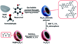
Scheme 2 depicts the design thought for the synthesis of nickel-based double-shelled hollow magnetic catalyst, Ni@Fe3O4–C. Firstly, Fe3O4 solid microspheres were formed by solvothermal approach. Then these solid microspheres were converted into hollow double-shelled Fe3O4-phenolic polymer using liquid ammonia as a structure directing agent and resorcinol–formaldehyde as a carbon source. Gas-bubble assisted Ostwald ripening process is responsible for this transformation.31 The beauty of this protocol was realized in the reaction conditions where the transformation of solid Fe3O4 to double-shell hollow magnetic nanoreactor was achieved in a single step at low temperature and shorter reaction time.43 Liquid ammonia produce gas bubbles (ammonia gas) in the reaction, which provides aggregation centers for the reaggregation of Fe3O4 crystals, thus, acts as soft template for the synthesis.31 Fe3O4–C is finally obtained by calcinating it in nitrogen atmosphere. Next, metalation is done using Ni(OAc)2 to form the desired catalyst.Characterization
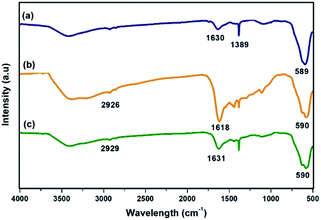
FT-IR spectra of the materials obtained at each step of the synthesis of Ni@Fe3O4–C catalyst is shown in Fig. 1. In all the spectra, the absorption band at around 589 cm−1 is attributed to the Fe–O bond vibration of the magnetite structure. In Fig. 1a, the peaks at 1389 and 1630 cm−1 are originated from carboxylate groups which are derived from trisodium citrate used during the synthesis of MNPs.44 The presence of carbon coating around magnetite shell was confirmed with the occurrence of bands at 1618 and 2926 cm−1 that correspond to C![[double bond, length as m-dash]](https://www.rsc.org/images/entities/char_e001.gif) C and –CH2 stretching modes respectively (Fig. 1b). Other peaks in the range of 1060–1510 cm−1 indicate the presence of C–O stretching and O–H bending vibrations,45 suggesting the presence of residual hydroxyl groups on the surface of Fe3O4–C that are accountable for active loading of Ni(II). Further, the spectrum of Ni@Fe3O4–C (Fig. 1c) exhibited slight shift in these values, confirming the successful loading of Ni(OAc)2.
C and –CH2 stretching modes respectively (Fig. 1b). Other peaks in the range of 1060–1510 cm−1 indicate the presence of C–O stretching and O–H bending vibrations,45 suggesting the presence of residual hydroxyl groups on the surface of Fe3O4–C that are accountable for active loading of Ni(II). Further, the spectrum of Ni@Fe3O4–C (Fig. 1c) exhibited slight shift in these values, confirming the successful loading of Ni(OAc)2.
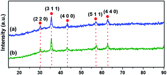
The crystallographic structure of materials is unveiled using powder XRD analysis (Fig. 2). The characteristic Bragg's diffraction peaks in the spectrum of Fe3O4 were obtained at 30.18° (2 2 0), 35.57° (3 1 1), 43.26° (4 0 0), 56.97° (5 1 1), and 62.83° (4 4 0) which were indexed to the inverse spinel structure of Fe3O4 (JCPDS card no. 19-629).46 Fig. 2b clearly depicts that there is nearly no notable variation in the pattern of magnetite, suggesting that the crystalline structure of Fe3O4 remains intact during the synthesis of the catalyst.
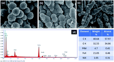
The structure and surface morphology of Fe3O4, Fe3O4–C and Ni@Fe3O4–C were investigated by field emission-scanning electron microscopic analysis. The images shown in Fig. 3, suggest that all the three materials have nearly uniform spherical morphology. Moreover, it can also be seen that Fe3O4–C and Ni@Fe3O4–C are porous materials. Fig. 3c indicates that the incorporation of Ni(OAc)2 did not alter the surface morphology of Fe3O4–C. SEM-coupled energy dispersive spectrum was also recorded to check the presence of different elements in the catalyst. Fig. 3d displays the peaks for Ni, C, Fe and O in the catalyst, indicating its successful formation. To calculate the amount of Ni in the catalyst, ICP-MS analysis was done. The approximate metal loading was found to be 0.47 mmol g−1.
To further investigate the morphology and size of the synthesized materials, TEM analysis was conducted. Fig. 4a confirmed that the magnetite particles are nearly uniform solid spheres with the mean diameter of about 360 nm. In Fig. 4b, we can clearly see a light-contrast cavity of approximately 100 nm, a dark inner magnetite shell and relatively light outer carbon shell with thickness of nearly 50 nm and 30–40 nm respectively. This confirms the successful formation of hollow Fe3O4–C microspheres. Interestingly, the nanometric cavity inside Fe3O4–C serves as an isolated chemical space that separate the guest species from outer bulk surrounding, thereby functioning as a nanoreactor. Fig. 4c, suggests that the structure of nanoreactor remained intact after the incorporation of nickel acetate.
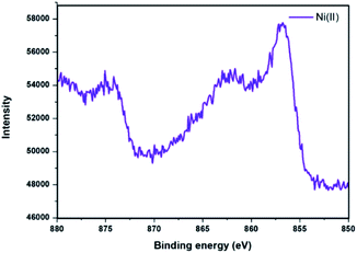
XPS analysis of Ni@Fe3O4–C catalyst was done to determine the oxidation state of nickel present in the catalyst (Fig. 5). The spectrum displayed peaks with binding energies of 856.2 eV and 862 eV which corresponds to the 2p3/2 and 2p1/2 peaks of nickel(II) ion.37,47,48 Thus, results revealed that the Ni ion has an oxidation state of +2 in Ni@Fe3O4–C catalyst.
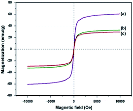
Saturation magnetization measurements (Ms) were also recorded for Fe3O4, Fe3O4–C and Ni@Fe3O4–C catalyst at room temperature (Fig. 6). The Ms values for Fe3O4 is 60.30 emu g−1 which is reduced to 32.9 emu g−1 and 29.66 emu g−1 in Fe3O4–C and Ni@Fe3O4–C respectively. This decrease could be attributed to the coating of non-magnetic carbon layer and incorporation of nickel acetate. However, even with this decrease in the saturation magnetization, Ni@Fe3O4–C catalyst could be effectively and efficiently removed from the reaction mixture within 30 s by applying an external magnet.
Catalytic activity test
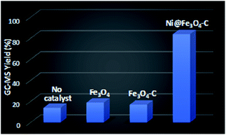
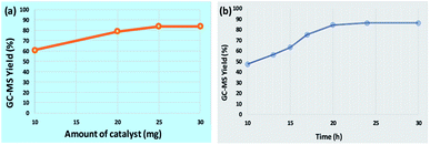
To assess the catalytic efficacy of Ni@Fe3O4–C in the synthesis of diaryl sulfides, the reaction of 4-cyanophenylhydrazine hydrochloride with 4-bromothiophenol was chosen as a model reaction. Initially, we performed some control experiments (Fig. 7). In the absence of catalyst, 14% of product was obtained. When Fe3O4 and Fe3O4–C were employed as catalysts, 19 and 17% of the desired product was formed. However, when Ni@Fe3O4–C was used as catalyst, a good yield of desired diaryl sulfide was observed. These results confirmed the significance of catalyst for the reaction.To study the influence of various parameters on the reaction and to maximize the yield of the desired product, model substrates were treated under various conditions using different solvents, bases, time, amount of base and catalyst loading. Fig. 8 shows the effect of different solvents. Fortunately, with water as a solvent, the activity of our catalyst was found to be comparable or superior than DMSO, DMF, acetonitrile, methanol, THF and toluene, thus, making the protocol green. Next, we screened the effect of base on the synthesis of diaryl sulfides. As depicted in Table 1, in the absence of any base, trace amount of the desired product was formed, confirming the necessity of base in the synthesis (Table 1, entry 1). Moreover, results confirmed that the activity of catalyst is sensitive to the base used (Table 1, entries 2–8). Among all, K2CO3 was found to be the most suitable base. Moreover, amount of base also plays an important role in maximizing the yield of the desired product (Table 1, entries 9–10). 3 equiv. of K2CO3 was found to be optimum for the reaction. The effect of catalyst amount on the yield of diaryl sulfide is shown in Fig. 9a. 25 mg of the catalyst is required to catalyze the reaction. Next, we conducted the reaction at different reaction times of 10–30 h (Fig. 9b). Results state that 20 h is the optimized time for the reaction.
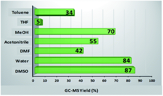 | ||
| Fig. 8 Effect of various solvents. Reaction conditions: 4-cyanophenylhydrazine hydrochloride (1 mmol), 4-bromothiophenol (1 mmol), K2CO3 (4 equiv.), catalyst (30 mg), solvent (3 mL), rt, 24 h. | ||
| Entry | Base | Amount of base (equiv.) | Yieldb (%) |
|---|---|---|---|
| a Reaction conditions: 4-cyanophenylhydrazine hydrochloride (1 mmol), 4-bromothiophenol (1 mmol), base, catalyst (30 mg), H2O (3 mL), rt, 24 h.b GC-MS yield.c Nitrogen atmosphere. | |||
| 1 | — | — | Trace |
| 2 | Cs2CO3 | 4 | 60 |
| 3 | Et3N | 4 | 39 |
| 4 | K2CO3 | 4 | 84 |
| 5 | NaOH | 4 | 51 |
| 6 | DBU | 4 | 27 |
| 7 | Li2CO3 | 4 | 41 |
| 8 | Na2CO3 | 4 | 48 |
| 9 | K2CO3 | 2 | 76 |
| 10 | K2CO3 | 3 | 84 |
| 11c | K2CO3 | 3 | Trace |
Substrate scope
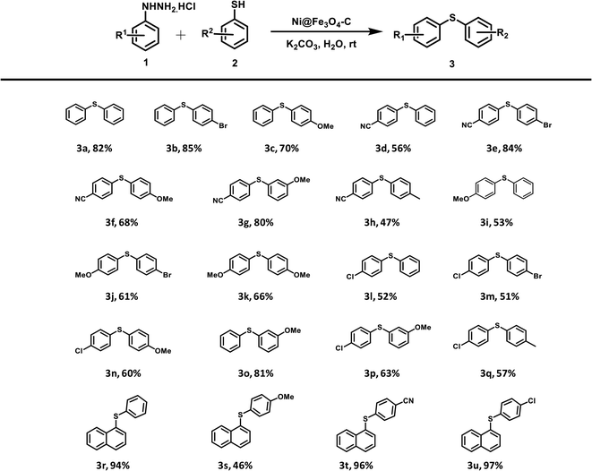
Finally, with these optimized reaction conditions in hand, a range of Ni@Fe3O4–C catalyzed reactions between different arylhydrazine hydrochlorides and thiophenols were conducted (Table 2). Various diaryl sulfides are obtained in moderate to good yields. Arylhydrazines and arenethiols with electron-donating substituents presented the corresponding products in good yields. Chloro-substituted arylhydrazine coupled with various arenethiols to afford diaryl sulfides in good yields. Even the strong electron-withdrawing group (–CN) on arylhydrazine gave the corresponding coupling product in good to high yields. Moreover, the electron-withdrawing group is well tolerated on thiophenols as p-bromothiophenol also furnished the desired products in moderate to high yields. On the grounds of mechanistic studies (Scheme S1†) and previous reports, a plausible mechanism has been proposed which is outlined as Scheme S2.† Next, we compared the outcomes of our work with various homogeneous and heterogeneous catalysts that have been reported in literature for the C–S coupling reaction to form diaryl sulfides. The comparison results are summarized in Table S1.† To our delight, the catalytic activity and reaction conditions of our catalyst was better than other catalytic systems.Heterogeneity test
To validate the heterogeneous nature of the catalyst, a hot filtration test was performed with Ni@Fe3O4–C for oxidative C–S coupling reaction using model substrates, 4-cyanophenylhydrazine hydrochloride and 4-bromothiophenol, under optimized conditions. At the end of the reaction, the catalyst was separated using an external magnet. The resulting filtrate was examined by ICP-MS analysis, which showed negligible metal leaching. This result confirmed the true heterogeneous nature of the catalyst.Recyclability
Fast and easy recovery and recyclability of a catalyst are the prime features that stimulate the design of clean processes and technologies. So, we investigated the recyclability of Ni@Fe3O4–C catalyst in oxidative C–S coupling reaction under optimized parameters. At the end of each reaction cycle, the catalyst was separated from the reaction mixture with the assistance of an external magnet, washed with ethanol, dried under vacuum and reused for subsequent reactions. Fig. S1† depicts that the activity of the catalyst remained nearly unchanged even after 7 cycles. We also checked the stability of the catalyst after 7 runs by FT-IR, SEM, VSM and ICP-MS analyses. The close resemblance of the FT-IR spectrum and SEM image of fresh and reused catalyst indicates that the functional groups, structure and morphology of the catalyst remained nearly unaltered even after seven consecutive cycles (Fig. S2 and S3†). Fig. S4† represents the VSM curve of recovered catalyst that suggest a slight decrease in saturation magnetization. Moreover, the ICP-MS analysis of recovered catalyst confirmed negligible leaching of nickel acetate.Experimental section
Details of the materials, reagents and instruments used can be found in ESI.†Synthesis of Fe3O4 microspheres
Solid Fe3O4 microspheres were synthesized using solvothermal method.31 Briefly, 4.0 g of sodium acetate is dissolved in 40 mL of diethylene glycol. This solution is then transferred to a flask containing a stirred solution of 1.95 g FeCl3·6H2O, 0.1 g trisodium citrate and 40 mL ethylene glycol. The resulting mixture was further stirred for additional 30 min, and finally transferred to a teflon-lined stainless-steel autoclave which was then heated at 200 °C for 10 h. After completion of the reaction, the autoclave was left to cool to room temperature. The obtained black powder of Fe3O4 microspheres was separated using an external magnet, washed with water and ethanol, and dried under vacuum at 50 °C.Synthesis of Fe3O4–C microspheres
The formation of Fe3O4–C microspheres is based on gas bubble assisted Ostwald ripening process.31 200 mL of ethanol/water (3![[thin space (1/6-em)]](https://www.rsc.org/images/entities/char_2009.gif) :
:![[thin space (1/6-em)]](https://www.rsc.org/images/entities/char_2009.gif) 1) mixture was taken in a round bottom flask. Next, 0.25 g of solid Fe3O4 microspheres were added to it. The flask was then placed under sonication. After 15 min, resorcinol (0.4 g) and aqueous ammonia (4.0 mL) were added and solution was stirred at room temperature for 10 min. Next, 0.6 mL of formaldehyde solution was added dropwise. The resultant reaction mixture was stirred at room temperature for 1 h and then heated at 80 °C for 5 h. The hollow Fe3O4-phenolic polymer was removed through magnetic separation, washed with water and ethanol several times and finally dried under vacuum at 50 °C. The obtained Fe3O4-phenolic polymer was further heated at 600 °C under N2 atmosphere for 3 h to obtain double-shelled hollow Fe3O4–C nanoreactor.
1) mixture was taken in a round bottom flask. Next, 0.25 g of solid Fe3O4 microspheres were added to it. The flask was then placed under sonication. After 15 min, resorcinol (0.4 g) and aqueous ammonia (4.0 mL) were added and solution was stirred at room temperature for 10 min. Next, 0.6 mL of formaldehyde solution was added dropwise. The resultant reaction mixture was stirred at room temperature for 1 h and then heated at 80 °C for 5 h. The hollow Fe3O4-phenolic polymer was removed through magnetic separation, washed with water and ethanol several times and finally dried under vacuum at 50 °C. The obtained Fe3O4-phenolic polymer was further heated at 600 °C under N2 atmosphere for 3 h to obtain double-shelled hollow Fe3O4–C nanoreactor.
Preparation of Ni@Fe3O4–C catalyst
100 mg of Fe3O4–C were sonicated in 40 mL methanol for 15 min. Then, 25 mg Ni(OAc)2 was added. Finally, the reaction mixture was stirred at room temperature for 5 h. The catalyst was collected using external magnet, washed with water and ethanol, and finally dried at 50 °C under vacuum.General experimental procedure for the synthesis of diaryl sulfides catalyzed by Ni@Fe3O4–C catalyst
In an oven dried round bottom flask, thiol (1 mmol), arylhydrazine (1 mmol), K2CO3 (3 equiv.), Ni@Fe3O4–C (25 mg) and H2O (3 mL) were added. The reaction mixture was sonicated for 15 minutes. Then, it was stirred at room temperature under open atmosphere for 20 h. After completion of the reaction, the reaction mixture was extracted with ethyl acetate and organic phase was dried over anhydrous Na2SO4. The obtained products were analyzed using GC-MS.Conclusions
In conclusion, we have developed an efficient nickel-based magnetic double-shelled nanoreactor for the confined oxidative C–S cross-coupling of arenethiols and arylhydrazines under aerobic conditions to form unsymmetrical diaryl sulfides. A diverse range of diaryl sulfides are synthesized using water as green solvent at room temperature under oxidant- and ligand-free conditions. Interestingly, the use of arylhydrazines as electrophilic counterpart highly promotes the principles of green chemistry as only environmentally safe by-products; nitrogen and water are formed. Besides, the catalyst can be easily recovered from the reaction medium using external magnet and can be recycled up to seven consecutive cycles without appreciable loss in catalytic activity. We expect that the present protocol could be extended to pharmaceutical industries to synthesize medicinally important diaryl sulfides in an effective and sustainable way.Conflicts of interest
There are no conflicts to declare.Acknowledgements
Gunjan Arora, Radhika Gupta, Pooja Rana and Priya Yadav gratefully acknowledge CSIR and UGC for awarding the research fellowships. Also, the authors thank USIC, University of Delhi, India and TERI, India for providing instrumentation facilities.Notes and references
- J.-Y. Li, J. Huang, S.-J. Zhang, C. Yao, W.-W. Sun, B. Liu, Y. Zhou and B. Wu, Tetrahedron Lett., 2019, 60, 895–899 CrossRef CAS.
- Z.-B. Dong, M. Balkenhohl, E. Tan and P. Knochel, Org. Lett., 2018, 20, 7581–7584 CrossRef CAS PubMed.
- M. J. Böhm, C. Golz, I. Rüter and M. Alcarazo, Chem. Eur J., 2018, 24, 15026–15035 CrossRef PubMed.
- R. G. Arrayás and J. C. Carretero, Chem. Commun., 2011, 47, 2207–2211 RSC.
- A. Kausar, S. Zulfiqar and M. I. Sarwar, Polym. Rev., 2014, 54, 185–267 CrossRef CAS.
- P. Anbarasan, H. Neumann and M. Beller, Chem. Commun., 2011, 47, 3233–3235 RSC.
- G. De Martino, M. C. Edler, G. La Regina, A. Coluccia, M. C. Barbera, D. Barrow, R. I. Nicholson, G. Chiosis, A. Brancale and E. Hamel, J. Med. Chem., 2006, 49, 947–954 CrossRef CAS PubMed.
- Y. Wang, S. Chackalamannil, Z. Hu, J. W. Clader, W. Greenlee, W. Billard, H. Binch III, G. Crosby, V. Ruperto and R. A. Duffy, Bioorg. Med. Chem. Lett., 2000, 10, 2247–2250 CrossRef CAS PubMed.
- J. A. Fernández-Salas, A. P. Pulis and D. J. Procter, Chem. Commun., 2016, 52, 12364–12367 RSC.
- S. W. Kaldor, V. J. Kalish, J. F. Davies, B. V. Shetty, J. E. Fritz, K. Appelt, J. A. Burgess, K. M. Campanale, N. Y. Chirgadze and D. K. Clawson, J. Med. Chem., 1997, 40, 3979–3985 CrossRef CAS PubMed.
- G. Liu, J. R. Huth, E. T. Olejniczak, R. Mendoza, P. DeVries, S. Leitza, E. B. Reilly, G. F. Okasinski, S. W. Fesik and T. W. von Geldern, J. Med. Chem., 2001, 44, 1202–1210 CrossRef CAS PubMed.
- C. C. Johansson Seechurn, M. O. Kitching, T. J. Colacot and V. Snieckus, Angew. Chem., Int. Ed., 2012, 51, 5062–5085 CrossRef CAS PubMed.
- I. P. Beletskaya and V. P. Ananikov, Chem. Rev., 2011, 111, 1596–1636 CrossRef CAS PubMed.
- F. Diederich and P. J. Stang, Metal-Catalyzed Cross-Coupling Reactions, John Wiley & Sons, 2008 Search PubMed.
- P. Guan, C. Cao, Y. Liu, Y. Li, P. He, Q. Chen, G. Liu and Y. Shi, Tetrahedron Lett., 2012, 53, 5987–5992 CrossRef CAS.
- K. Swapna, S. N. Murthy, M. T. Jyothi and Y. V. D. Nageswar, Org. Biomol. Chem., 2011, 9, 5989–5996 RSC.
- K. Kanemoto, Y. Sugimura, S. Shimizu, S. Yoshida and T. Hosoya, Chem. Commun., 2017, 53, 10640–10643 RSC.
- M. Jiang, H. Li, H. Yang and H. Fu, Angew. Chem., Int. Ed., 2017, 56, 874–879 CrossRef CAS PubMed.
- A. Hosseinian, R. Mohammadi, S. Ahmadi, A. Monfared and Z. Rahmani, RSC Adv., 2018, 8, 33828–33844 RSC.
- T. Taniguchi, T. Naka, M. Imoto, M. Takeda, T. Nakai, M. Mihara, T. Mizuno, A. Nomoto and A. Ogawa, J. Org. Chem., 2017, 82, 6647–6655 CrossRef CAS PubMed.
- C. Wang, Z. Zhang, Y. Tu, Y. Li, J. Wu and J. Zhao, J. Org. Chem., 2018, 83, 2389–2394 CrossRef CAS PubMed.
- X. Ren, S. Tang, L. Li, J. Li, H. Liang, G. Li, G. Yang, H. Li and B. Yuan, J. Org. Chem., 2019, 84, 8683–8690 CrossRef CAS PubMed.
- G.-H. Wang, K. Chen, J. Engelhardt, H. Tüysüz, H.-J. Bongard, W. Schmidt and F. Schüth, Chem. Mater., 2018, 30, 2483–2487 CrossRef CAS.
- H. Chen, K. Shen, Q. Mao, J. Chen and Y. Li, ACS Catal., 2018, 8, 1417–1426 CrossRef CAS.
- G. Li and Z. Tang, Nanoscale, 2014, 6, 3995–4011 RSC.
- X. Jiang, F. Wang, W. Cai and X. Zhang, J. Alloys Compd., 2015, 636, 34–39 CrossRef CAS.
- N. Zhang, X. Fu and Y.-J. Xu, J. Mater. Chem., 2011, 21, 8152–8158 RSC.
- J. Liu, S. Z. Qiao, S. Budi Hartono and G. Q. Lu, Angew. Chem., Int. Ed., 2010, 49, 4981–4985 CrossRef CAS PubMed.
- T. Liu, L. Zhang, B. Cheng and J. Yu, Adv. Energy Mater., 2019, 9, 1803900 CrossRef.
- S. Cao, J. Chang, L. Fang and L. Wu, Chem. Mater., 2016, 28, 5596–5600 CrossRef CAS.
- G. Arora, M. Yadav, R. Gaur, R. Gupta and R. K. Sharma, ChemistrySelect, 2017, 2, 10871–10879 CrossRef CAS.
- P. Rana, R. Gaur, R. Gupta, G. Arora, J. Anireddy and R. K. Sharma, Chem. Commun., 2019, 55, 7402–7405 RSC.
- R. Gaur, M. Yadav, R. Gupta, G. Arora, P. Rana and R. K. Sharma, ChemistrySelect, 2018, 3, 2502–2508 CrossRef CAS.
- R. Gupta, M. Yadav, R. Gaur, G. Arora and R. K. Sharma, Green Chem., 2017, 19, 3801–3812 RSC.
- R. K. Sharma, R. Gaur, M. Yadav, A. Goswami, R. Zbořil and M. B. Gawande, Sci. Rep., 2018, 8, 1901 CrossRef PubMed.
- R. K. Sharma, M. Yadav, Y. Monga, R. Gaur, A. Adholeya, R. Zboril, R. S. Varma and M. B. Gawande, ACS Sustainable Chem. Eng., 2016, 4, 1123–1130 CrossRef CAS.
- R. K. Sharma, M. Yadav, R. Gaur, Y. Monga and A. Adholeya, Catal. Sci. Technol., 2015, 5, 2728–2740 RSC.
- R. K. Sharma, M. Yadav, R. Gaur, R. Gupta, A. Adholeya and M. B. Gawande, ChemPlusChem, 2016, 81, 1312–1319 CrossRef CAS PubMed.
- R. K. Sharma, R. Gaur, M. Yadav, A. K. Rathi, J. Pechousek, M. Petr, R. Zboril and M. B. Gawande, ChemCatChem, 2015, 7, 3495–3502 CrossRef CAS.
- P. Yadav, M. Yadav, R. Gaur, R. Gupta, G. Arora, P. Rana, A. Srivastava and R. K. Sharma, ChemCatChem, 2020, 12, 2488–2496 CrossRef CAS.
- R. Sharma, S. Yadav, R. Gupta and G. Arora, J. Chem. Educ., 2019, 96, 3038–3044 CrossRef CAS.
- M. Yadav and R. K. Sharma, Curr. Opin. Green and Sustain. Chem., 2019, 15, 47–59 CrossRef.
- X. Liu, Y. Li, W. Zhu and P. Fu, CrystEngComm, 2013, 15, 4937–4947 RSC.
- Y. Shao, L. Zhou, C. Bao, Q. Wu, W. Wu and M. Liu, New J. Chem., 2016, 40, 9684–9693 RSC.
- L. Kong, X. Lu, X. Bian, W. Zhang and C. Wang, ACS Appl. Mater. Interfaces, 2010, 3, 35–42 CrossRef PubMed.
- J. Liu, J. Cheng, R. Che, J. Xu, M. Liu and Z. Liu, ACS Appl. Mater. Interfaces, 2013, 5, 2503–2509 CrossRef CAS PubMed.
- G. B. B. Varadwaj, S. Rana and K. Parida, RSC Adv., 2013, 3, 7570–7578 RSC.
- J. Cao, X. Zhang, X. He, L. Chen and Y. Zhang, J. Mater. Chem., 2013, 1, 3625–3632 RSC.
Footnote |
| † Electronic supplementary information (ESI) available. See DOI: 10.1039/d0ra02287j |
| This journal is © The Royal Society of Chemistry 2020 |

