 Open Access Article
A carbon nanotube approach for efficient thermally insulating material with high mechanical stability and fire-retardancy†
Hang Zhan,
Qiang Qiang Shi,
Guang Wu and
Jian Nong Wang *
*
School of Mechanical and Power Engineering, East China University of Science and Technology, 130 Meilong Road, Shanghai 200237, China. E-mail: jnwang@ecust.edu.cn; Tel: +86-21-64252360
First published on 8th June 2020
Abstract
For applications in energy-saving buildings, aerospace industry, and wearable electronic devices, thermally insulating materials (TIMs) are required to possess not only low thermal conductivity but also light weight, mechanical robustness, and environmental stability. However, conventional TIMs can rarely meet these requirements. To overcome this shortcoming, we propose a new strategy for preparing TIMs. This is based on the design of a highly porous structure from carbon nanotubes (CNTs). The CNT structure is constructed by continuous winding of a hollow cylindrical CNT assembly from a high-temperature furnace and subsequent modification by the deposition of amorphous carbon (AC). The resultant sponge-like material is shown to have a record-low density of 2–4 mg cm−3 and a record-low thermal conductivity of 10–14 mW m−1 K−1. Combined with this thermal property, the sponge material also possesses fire-retardancy during burning, mechanical robustness after repeated loading and unloading to a high strain of 90%, and environmental stability from 535 to −196 °C. Such a combination of physical and mechanical properties results from the strengthening of the porous structure by virtue of AC deposition on CNT surfaces and junctions. The high performance of the new TIM constitutes the foundation for it to be used in wide areas, especially under the harsh conditions requiring multifunctionality.
1 Introduction
Thermally insulating materials (TIMs) have attracted tremendous research due to the growing need for efficient energy use,1 especially in the fields of energy-saving building materials,2,3 aerospace industry, and electronic devices.4,5 For many of these applications, TIMs are required to be lightweight and fire-retardant with ultralow thermal conductivity (T/C) (or T/C coefficient λ) and excellent mechanical and thermal stabilities. However, conventional TIMs can hardly meet these requirements.Numerous methods have been developed to fabricate TIMs. In the past, some biopolymer-based materials (i.e., natural wood) were modified and subsequently used as TIMs. However, the thermal conductivities of wood composites are high (λaxial = 320 mW m−1 K−1, λradial = 150 mW m−1 K−1) due to their high bulk densities (>600 mg cm−3).2,6 Other conventional TIMs also have high thermal conductivities, such as polymer/clay aerogel (λ = 45 mW m−1 K−1), expanded polystyrene (EPS: λ = 30–40 mW m−1 K−1), and porous aramids (λ = 28 mW m−1 K−1).3,7,8 Besides, TIMs based on wood/polymer composites are not heat and fire resistant, which greatly limits their applications.
Generally, thermal conduction is contributed by three components: gas phase, solid phase, and radiation. Among them, the contribution from radiation is very small, and the efficiency of solid conduction is usually higher than gas conduction. The use of nanosized one- and two-dimensional materials such as carbon nanotubes (CNTs) and silicate nanorods9–11 can significantly reduce the heat conduction by solid by the creation of phonon barriers.12,13 Furthermore, the relative contributions of the three components depend upon the bulk density of the material.14 The solid conduction clearly increases with increasing the density, whereas the reverse is true for the gas or radiation conduction.15 Hence, low density and high porosity are crucial factors in building TIMs with very low thermal conductivity.
Silica aerogels are the most widely used TIMs at present. These materials have a very low thermal conductivity (λ = 15–40 mW m−1 K−1) resulting from their attractive characteristics such as a porosity higher than 90%, specific surface area between 250 and 800 m2 g−1, and bulk density ranging from 0.003 to 0.3 g cm3.16 But, the highly porous structure is detrimental to the mechanical strength of the TIMs, and their fragile mechanical performance makes silica aerogels susceptible to thermal insulation failure.17 For the purpose of improving their mechanical properties, silica aerogels have been modified by the insertion of carbon nanomaterials, such as CNTs,18–20 carbon nanofibers,21 and graphene22 as these carbon materials have excellent mechanical properties, including high compressibility, high strength, and high Young's modulus.23 However, the insertion of these materials is not easy at all because it is difficult to disperse them. In addition, the insertion of these materials inevitably increases the density and thermal conduction and thus reduces the thermal insulation of the pristine aerogels.
Until now, it is still very challenging to achieve efficient TIMs with lightweight, mechanically flexible and robust, fire-retardant, and high temperature resistant properties by a cost-effective method. Here, we introduce a relatively simple method to fabricating high performance TIMs with these required properties based on a CNT assembly. First, a hollow cylindrical CNT assembly (HCCA) is prepared with our previous spray pyrolysis method,24,25 and winded to form a 3-dimensional (3D) loose multi-layered CNT assembly (LMCA). Then, a secondary reaction is implemented between CNTs and acetylene (C2H2) at high temperature. With the deposition of amorphous carbon (AC) on CNT joints and sidewalls, the original LMCA evolves to a sponge-like elastic object. Due to the uniform 3D nano-porous structure and ultralow density (2.1 mg cm3), the CNT sponge possesses a very low thermal conductivity (λ = 10–14 mW m−1 K−1), excellent fire-retardancy, high temperature-resistance, and particularly remarkable elastic recoverability under compressive cycling. The combination of these properties endows the CNT sponge with great potential applications in the field of thermal insulation.
2 Experimental methods
2.1 Fabrication of hollow cylinder-like CNT assembly
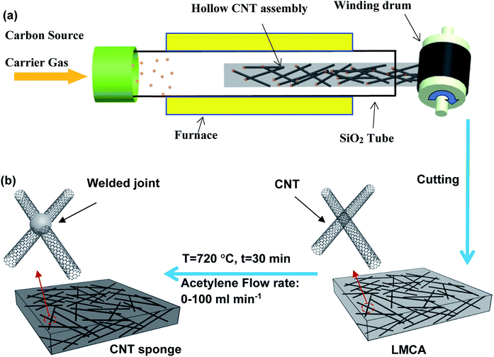
The schematic of CNT synthesis and its assembling into a HCCA is shown in Fig. 1a. Using a quartz tube with an inner diameter of 40 mm as a reactor, the carbon source (ethanol), catalyst precursor (ferrocene, 0.2–1.0 wt%), and growth promoter (thiophene, 0.05–0.3 wt%) were mixed and injected into the high temperature zone (950–1050 °C) at a rate of 2–15 mL min−1 with a N2 carrier gas at a flow rate of 16–100 L min−1. CNTs self-assembled into a HCCA in the low temperature region, and the assembly was blown out by the carrier gas from the reactor to the open-air environment.2.2 Formation of thermal insulating CNT sponge
A winding drum with a diameter of 200 mm was used for winding the CNT assembly. The HCCA was stacked on the drum layer-by-layer to form an LMCA. The winding rate was fixed at 4–10 m min−1. Under given experimental conditions, including the winding rate and the substrate surface area, the thickness of the LMCA was adjusted by controlling the winding time. For the present study, an LMCA was prepared with a width of 200 mm, length of 600 mm, and thickness of 10–20 mm. Such an LMCA was cut into smaller pieces of 200 mm long and 200 mm wide and used as a preform for the preparation of the final sponge sample. In order to introduce welding between CNT joints by AC, the sponge preform was heat treated at 720 °C in the presence of an acetylene flow at a rate of 20–100 mL min−1 for 30 min (Fig. 1b).2.3 Structure characterization and analysis
Morphology and structure of CNT sponges were characterized by high resolution transmission electron microscopy (HRTEM, EOL-2010F, accelerating voltage of 200 kV) and field emission scanning electron microscope (FESEM, GeminSEM 520). High temperature resistance and the content of Fe in the CNT sponge were analyzed by thermo-gravimetric analysis (TGA, Netzsch Model STA 409 PC) at a heating rate of 10 °C min−1 in an air environment. Raman spectroscopy was carried out by a Raman spectrometer (Bruker Senterra R200-L) using a laser of 532 nm wavelength. The diameter of CNTs was measured by a software (Nano Measurer 1.2) from their SEM images.2.4 Thermal property measurement
Thermal transport properties were measured by a transient plane source (TPS) analyzer (Hot Disk TPS 2500, Sweden). The instrument was operated at a 20 mW output power in the transient mode with the use of a 6.4 mm Ni wire sensor. Five independent measurements of thermal diffusivity, α (mm2 s−1), were made in an anisotropic mode for each sample. The specific heat capacity of each sponge sample, Cp (J g−1 K−1), was measured by differential scanning calorimetry (DSC) using an integrated thermal analyzer (TG209F1-GC 7820A-MS5978B, Netzsch). The bulk density of a CNT sponge, ρ (g cm−3), was determined by measuring its weight and volume. Finally, the thermal conductivity coefficient, λ (mW m−1 K−1), for each sponge sample was calculated from the following equation:| λ = α × ρ × Cp. | (1) |
2.5 Mechanical testing
Compressive testing was carried out by a compressive tester (Zolix SC 300-1A) equipped with two flat-surface compression stages and a 6N load cell. Materials were cut into small cubic blocks with a dimension of 10 mm × 10 mm × 10 mm. This sample was compressed at a strain rate of 1.67 × 10⁻² s−1 to 90% strain. Such compressive testing was repeated for some samples and each cycle of the loading–unloading behavior was recorded.3 Results and discussion
3.1 Fabrication of CNT sponge preform
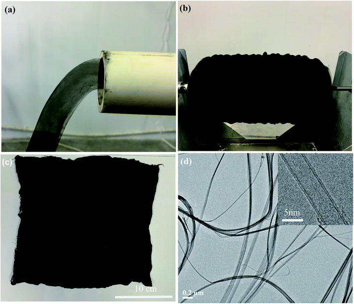
Under the present experimental conditions, as the reaction solution was injected for pyrolysis, CNTs were continuously synthesized at the high-temperature zone, self-assembled into an HCCA in the low-temperature region, and eventually driven out from the reactor to air atmosphere by the carrier gas (Fig. 2a). The HCCA was winded on the winding drum layer-by-layer, leading to the formation of an LMCA with a loose and porous structure (Fig. 2b). The LMCA could be easily taken off from the winding drum for subsequent uses (Fig. 2c). TEM imaging showed that the HCCA contained mainly CNT bundles, and the CNT bundles were entangled and intertwined into a 3D nano-porous network (Fig. 2d). Examination by high-resolution TEM revealed that the CNT bundles were made up of double walled CNTs with a diameter of ∼5 nm (Fig. 2d, inset).3.2 Structural features of CNT sponge
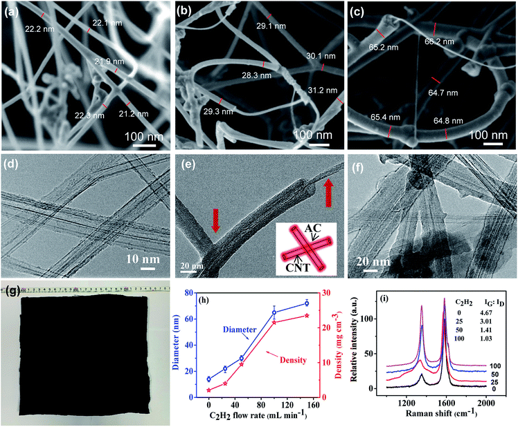
After the sponge preform had been heat treated at 720 °C for 30 min under the flow of C2H2, it turned to be a robust sponge-like material with its original sizes (length, width, and thickness) and black color remaining almost intact (Fig. 3g). ESI Fig. S1† illustrates a typical low magnification SEM image of the CNT sponge exhibiting a smooth surface with homogeneous pores. SEM imaging at a higher magnification showed that the sponge was actually comprised of intertangled CNTs with abundant pores in between, and the CNTs generally distributed uniformly throughout the sponge at the micrometer scale and above. At the nanometer scale, each CNT constituted a high aspect-ratio continuous skeleton. CNT aggregation was noticeable, and the pores had a size distribution over a large range from tens to thousands of nanometers. It is worth noting that no apparent difference in porous structure was observed between the top surface and side walls of the sponge (Fig. 3b vs. ESI Fig. S2†).The porous structures of the sponges obtained under different flow rates of C2H2 were studied, and the CNT diameter and the sponge density were measured (Fig. 3h). The sponge preform before heat treatment had a loose and porous network consisting of randomly oriented CNTs, resulting in a low density of 2.1 mg cm−3 and high porosity of ∼99%. This density is much lower than those of CNT aerogel/sponges, graphene foams (4.0–25.5 mg cm−3) reported in the literature,26–33 and even lower than those of some silica aerogels.16 After heat treatment at a low C2H2 flow rate of 25 mL min−1, a very thin AC coating was observable on CNT surfaces, resulting in an increase of the diameter of the CNT bundle from the original ∼14 nm (ESI Fig. S3†) to ∼22 nm and the density from the original 2.1 to 4.0 mg cm−3, and this increase amounts to an AC loading of ∼90.5 wt%. At a higher C2H2 flow rate, more AC was deposited on CNTs, and the AC preferably accumulated at joints rather than CNT sidewalls. Since the coating was not uniform along CNTs, the diameter measurement was only conducted near CNT joints. The average diameter and density tended to increase with increasing C2H2 flow rate. Namely, as the flow rate changed from 0 → 25 → 50 → 100 → 150 mL min−1, the diameter varied from 14 → 22 → 30 → 65 → 72 nm, and density from 2.1 → 4.0 → 9.5 → 21.5 → 23.5 mg cm−3 (Fig. 3a–c). These observations indicate an increase of AC deposition and the deposition appeared to be saturated at 100 mL min−1 and beyond.
More detailed features of CNT sponges were characterized by TEM. In the CNT sponge preform, it was hard to observe any uniform and continuous coating or particle-like coating on CNT surfaces due to the good graphitic structure of CNTs (Fig. 3d). After the treatment at a low C2H2 flow rate, a very thin AC coating was observed on CNT surfaces. Furthermore, the core–shell structure was clearly recognized at the end of the tube (Fig. 3e). With increasing C2H2 flow rate, the thickness of AC coating on the surface of CNTs increased. AC was uniformly and smoothly coated along the whole CNTs, no matter whether the coating was relatively thin or thick. Although the TEM sample experienced ultrasonic dispersion during the process of sample preparation, there was no obvious interface between AC coating and CNT surface. This observation indicates a strong mutual binding between AC and CNT surface. Besides, some CNT crossings in the CNT network had been welded by AC (Fig. 3e and f). The welded crossings may be responsible for the improved mechanical strength and structural stability of the sponge under compression.
To further characterize the degree of AC coating, Raman spectroscopy was applied. On a Raman spectrum of CNTs, the G mode located at the high frequency of 1580 cm−1 originates from the Eg2 vibration mode of the graphite plane, which corresponds to a complete graphitic structure and reflects the orderliness of the material. Generally, the D peak at ∼1340 cm−1 is induced by the structural defects of CNTs and AC adsorbed on the CNT walls. As shown in Fig. 3i, the ratio of G peak and D peak intensities decreased with increasing C2H2 flow, indicating the accumulation of more AC on CNT surfaces.
3.3 Thermal properties of CNT sponge
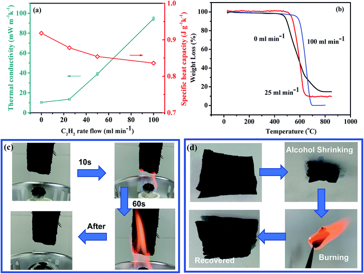
According to eqn (1), the thermal conductivity of the CNT sponge is determined by its specific heat capacity, density, and thermal diffusivity. The CNT sponge can be regarded as a composite of CNTs and air, and its specific heat capacity should be between that of air (1.003 J g−1 K−1) and that of CNT (∼0.7 J g−1 K−1). As shown in Fig. 4a, the specific heat capacities of the CNT sponges from 0, 25, 50, and 100 mL min−1 C2H2 flow rates were measured to be 0.918, 0.878, 0.854, 0.836 J g−1 K−1 at room temperature (25 °C), respectively. The slight difference of specific heat capacity among different sponges was directly correlated with their different densities and porosities. In the extreme case when the original LMCA was densified into a solid film by a liquid, the original pore structure was largely shrunk, and its density could be as high as 1.02 g cm−3, and its specific heat capacity was 0.707 J g−1 K−1, almost the same as that of pure CNTs.Fig. 4a shows the measured relationship between the thermal conductivity and the C2H2 flow rate. The original sponge preform with a very low density of 2.1 mg cm−3 exhibited a very low thermal conductivity (λ = 9.6–10.5 mW m−1 K−1). Although the welding of AC could block the pores in the sponge, resulting in a decrease of the thermal insulation performance of the material, it was found that a small amount of AC welding didn't change the thermal conductivity of the material greatly. For example, when the original sponge preform was treated at a low C2H2 flow rate of 25 mL min−1, the thermal conductivity only increased slightly to 12.6–14.5 mW m−1 K−1, representing a record-low thermal conductivity among the silica, CNT, carbon nanofiber, and graphene aerogel materials reported so far.9–11 As the flow rate increased to 50 and 100 mL min−1, the thermal conductivity of the CNT sponge increased to 37.6–40.4 and 92.4–96.4 mW m−1 K−1, respectively, as a result of the obvious increase of sponge density. As the density continued to increase to the level for a solid film (1.02 g cm−3), the thermal conductivity increased to 560 mW m−1 K−1. From the comparison of the thermal conductivity with the insulating materials published in the literature (ESI Table S1†),2,3,7,8,14,32–38 the present CNT sponge sample exhibits an outstanding thermal-insulating capability.
These results show that the high porosity or ultra-low bulk density and high contact thermal resistance may be the main causes of the good thermal insulation property of the sponge material. First, high porosity limits the cross-sectional area for heat conduction. Besides, a high porosity or low density means that the contact area between CNTs was such small that it was almost in the form of point contacts. Subsequently, the resultant high contact thermal resistance between CNTs or between the CNT and the deposited carbon suppressed phonon transport, leading to a further decrease of λ.39,40
For TIMs, it is necessary not only to have a very low thermal conductivity, but also to have a good high temperature stability and fire-retardancy. Conventional TIMs such as petroleum-based polymeric insulation materials are ignitable, and therefore require the addition of flame retardants.41,42 Unfortunately, many of the commonly used flame retardants are halogenated or phosphorous compounds with negative environmental and health impacts.43 To explore the thermal stability and fire retardancy of the present CNT sponge, we conducted TG and burning tests. As shown in Fig. 4b, the sponge preform began to lose weight at 476 °C in air atmosphere. After carbon deposition, the initial decomposition temperature of the sponge increased to 535 °C and 598 °C, suggesting an excellent thermal stability.
Vertical burning tests showed that the flame did not self-propagate and the CNT sponge from the treatment with the flow of 25 mL min−1 C2H2 did not shrink or undergo any other shape change after having been burned with an ethanol flame, suggesting very good flame retardancy (Fig. 4c and ESI Movie 1†). Graphene oxide foams displayed some fire retardancy too, but undergoing burning-induced shrinking much more than the CNT sponge.32 Furthermore, although the CNT sponge was shrunk by spraying polar solvents such as ethanol and acetone, with the removal of these solvents by burning, the sponge restored almost completely to its original dimension and structure, further suggesting its high thermal stability and fire-retardancy (Fig. 4d).
3.4 Mechanical properties of CNT sponge
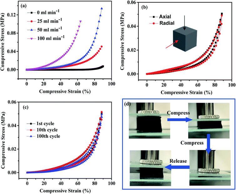
In order to systematically investigate the mechanical properties and structural stability of the sponge material, the CNT sponge from the treatment with the flow of 25 mL min−1 C2H2 was used for testing with the original LMCA also included for comparison. As shown in Fig. 5a, the stress–strain (ε = 90%) curve illustrates the typical deformation behavior of sponges and other elastomeric foams,30,44 that is, a linear elastic behavior at low strain and a plastic yielding plateau with subsequent stiffening at high strain. The strength and Young's modulus of the CNT sponge preform were about σ = 7.6 kPa and E = 75.3 kPa, respectively. The strength and Young's modulus were increased to σ = 50.6 kPa and E = 166.5 kPa for 25 mL min−1 C2H2 flow rate treatment, and σ = 133.6 kPa and E = 460 kPa for 50 mL min−1 C2H2 flow rate treatment. With a higher C2H2 flow rate treatment, the sponge became brittle and the compression deformation was less than 90%. Considering the thermal conductivity and mechanical properties of the material, the optimal C2H2 flow rate was 25 mL min−1. After the treatment at this condition, the CNT sponge had a specific Young's modulus of Es = 40.6 kNm kg−1, which is significantly higher than the values of silica aerogels (5–20 kNm kg−1).45 This high modulus is related to the extraordinary high moduli of CNTs and the AC coating. Besides, the compressive curve and stress at the axial direction were almost the same as those at the radial direction at the same strain (50.6 vs. 49.7 kPa at ε = 90%), showing a uniform structure of the CNT sponge (Fig. 5b).A 100 cycles of loading–unloading fatigue test at a compressive strain of 90% and a bending test were performed to evaluate the structural stability of the CNT sponge. The 25 mL min−1 C2H2 welded CNT sponge completely recovered to its original shape and dimension upon the release from a compressive strain of 90%, whereas the CNT sponge preform showed large unrecoverable plastic deformation during compressive loading. The loading/unloading testing revealed that the stress at 90% strain in each cycle was almost the same (ESI Fig. S4†), and Fig. 5c shows the stress–strain curves for the 1st, 10th and 100th cycles of compression testing. After 100 loading/unloading cycles, the maximum stress slightly decreased from 50.6 to 49.7 kPa under compression. No obvious plastic deformation was observed during the whole fatigue cycling. Photographs of the CNT sponge during one complete compressive cycling are shown in Fig. 5d for visualizing further the excellent mechanical stability of the sponge. In addition to compression stability, the sponges were also mechanically flexible. The sponges could be bent into any angles without apparent structural damage, thus suggesting its feasibility for applications on any shaped objects.
As shown in ESI Fig. S5 and ESI Movie 2,† the CNT sponge could also exist stably and flexibly in liquid nitrogen, reflecting its excellent low temperature stability. In a very humid environment, the sponge was superhydrophobic towards water droplets with a contact angle > 140°, suggesting a potential self-cleaning effect (ESI Fig. S6†). All these observations demonstrate that the CNT sponges are applicable and effective as a high-performance TIM with mechanical stability under extreme conditions.
4 Conclusions
In summary, an original LMCA was modified to a sponge-like material with the deposition of AC on CNT side walls and crossing joints. The AC coated CNT sponge demonstrated a combination of a record-low thermal conductivity (10–14 mW m−1 K−1) and excellent fire-retardancy. Such a low thermal conductivity is attributed to the abundant porous structure, ultra-low density of the sponge (2.1 mg cm−3), and the high contact thermal resistance between CNTs. With the AC welding and cross-linked 3D CNT network, the CNT sponge also possessed excellent mechanical robustness and environmental stability. The specific modulus of the CNT sponge was 40.6 kNm kg−1, being higher than the values for silica aerogels. The structural stability persisted during repeated loading and unloading to the high compressive strain of 90% and even after exposure to 535 °C in air and the ultra-low temperature of −196 °C in liquid nitrogen. The outstanding thermal insulating property combined with the excellent mechanical robustness and environmental stability provides substantial motivation to develop high-performance TIMs to be used in wide areas, particularly under harsh application conditions.Conflicts of interest
There are no conflicts to declare.Acknowledgements
This research was supported by National Key R&D Program of China (2018YFA0208404), National Natural Science Foundation of China (U1362104), and Innovation Program of Shanghai Municipal Education Commission.References
- J. L. Reyna and M. V. Chester, Nat. Commun., 2017, 8, 14916 CrossRef CAS PubMed.
- T. Li, M. Zhu, Z. Yang, J. Song, J. Dai, Y. Yao, W. Luo, G. Pastel, B. Yang and L. Hu, Adv. Energy Mater., 2016, 6, 1601122 CrossRef.
- B. P. Jelle, Energy Buildings, 2011, 43, 2549–2563 CrossRef.
- A. Fraleoni-Morgera and M. Chhikara, Adv. Eng. Mater., 2019, 21, 1801162 CrossRef.
- Y. Guo, K. Li, C. Hou, Y. Li, Q. Zhang and H. Wang, ACS Appl. Mater. Interfaces, 2016, 8, 4676–4683 CrossRef CAS PubMed.
- R. J. Moon, A. Martini, J. Nairn, J. Simonsen and J. Youngblood, Chem. Soc. Rev., 2011, 40, 3941–3994 RSC.
- N. Leventis, C. Chidambareswarapattar, D. P. Mohite, Z. J. Larimore, H. Lu and C. Sotiriou-Leventis, J. Mater. Chem., 2011, 21, 11981–11986 RSC.
- M. D. Gawryla, M. Nezamzadeh and D. A. Schiraldi, Green Chem., 2008, 10, 1078–1081 RSC.
- M. D. Losego, I. P. Blitz, R. A. Vaia, D. G. Cahill and P. V. Braun, Nano Lett., 2013, 13, 2215–2219 CrossRef CAS PubMed.
- G. Pernot, M. Stoffel, I. Savic, F. Pezzoli, P. Chen, G. Savelli, A. Jacquot, J. Schumann, U. Denker, I. Mönch, C. Deneke, O. G. Schmidt, J. M. Rampnoux, S. Wang, M. Plissonnier, A. Rastelli, S. Dilhaire and N. Mingo, Nat. Mater., 2010, 9, 491–495 CrossRef CAS PubMed.
- S. T. Huxtable, D. G. Cahill, S. Shenogin, L. Xue, R. Ozisik, P. Barone, M. Usrey, M. S. Strano, G. Siddons, M. Shim and P. Keblinski, Nat. Mater., 2003, 2, 731–734 CrossRef CAS PubMed.
- M. D. Losego, M. E. Grady, N. R. Sottos, D. G. Cahill and P. V. Braun, Nat. Mater., 2012, 11, 502–506 CrossRef CAS PubMed.
- J.-K. Yu, S. Mitrovic, D. Tham, J. Varghese and J. R. Heath, Nat. Nanotechnol., 2010, 5, 718–721 CrossRef CAS PubMed.
- N. Hüsing and U. Schubert, Angew. Chem., Int. Ed., 1998, 37, 22–45 CrossRef.
- N. Hüsing and U. Schubert, Angew. Chem., 1998, 110, 22–47 CrossRef.
- A. Lamy-Mendes, R. F. Silva and L. Durães, J. Mater. Chem. A, 2018, 6, 1340–1369 RSC.
- H. Maleki, L. Durães and A. Portugal, J. Non-Cryst. Solids, 2014, 385, 55–74 CrossRef CAS.
- S. Mahesh and S. C. Joshi, Int. J. Heat Mass Transfer, 2015, 87, 606–615 CrossRef CAS.
- U. K. H. Bangi, M. S. Kavale, S. Baek and H.-H. Park, J. Sol-Gel Sci. Technol., 2012, 62, 201–207 CrossRef CAS.
- B. Wang, K. Song, Y. Han and T. Zhang, J. Wuhan Univ. Technol., Mater. Sci. Ed., 2012, 27, 512–515 CrossRef CAS.
- T.-Y. Wei, S.-Y. Lu and Y.-C. Chang, J. Phys. Chem. C, 2009, 113, 7424–7428 CrossRef CAS.
- Y. Lei, Z. Hu, B. Cao, X. Chen and H. Song, Mater. Chem. Phys., 2017, 187, 183–190 CrossRef CAS.
- M. F. L. De Volder, S. H. Tawfick, R. H. Baughman and A. J. Hart, Science, 2013, 339, 535 CrossRef CAS PubMed.
- W. Xu, Y. Chen, H. Zhan and J. N. Wang, Nano Lett., 2016, 16, 946–952 CrossRef CAS PubMed.
- J. N. Wang, X. G. Luo, T. Wu and Y. Chen, Nat. Commun., 2014, 5, 3848 CrossRef CAS PubMed.
- W. Zhao, Y. Li, S. Wang, X. He, Y. Shang, Q. Peng, C. Wang, S. Du, X. Gui, Y. Yang, Q. Yuan, E. Shi, S. Wu, W. Xu and A. Cao, Carbon, 2014, 76, 19–26 CrossRef CAS.
- X. Gui, J. Wei, K. Wang, A. Cao, H. Zhu, Y. Jia, Q. Shu and D. Wu, Adv. Mater., 2010, 22, 617–621 CrossRef CAS PubMed.
- M. Yu, H. H. Funke, J. L. Falconer and R. D. Noble, Nano Lett., 2009, 9, 225–229 CrossRef CAS PubMed.
- M. B. Bryning, D. E. Milkie, M. F. Islam, L. A. Hough, J. M. Kikkawa and A. G. Yodh, Adv. Mater., 2007, 19, 661–664 CrossRef CAS.
- H. Wang, W. Lu, J. Di, D. Li, X. Zhang, M. Li, Z. Zhang, L. Zheng and Q. Li, Adv. Funct. Mater., 2017, 27, 1606220 CrossRef.
- X. Gui, H. Li, K. Wang, J. Wei, Y. Jia, Z. Li, L. Fan, A. Cao, H. Zhu and D. Wu, Acta Mater., 2011, 59, 4798–4804 CrossRef CAS.
- B. Wicklein, A. Kocjan, G. Salazar-Alvarez, F. Carosio, G. Camino, M. Antonietti and L. Bergström, Nat. Nanotechnol., 2015, 10, 277–283 CrossRef CAS PubMed.
- Q. Peng, Y. Qin, X. Zhao, X. Sun, Q. Chen, F. Xu, Z. Lin, Y. Yuan, Y. Li, J. Li, W. Yin, C. Gao, F. Zhang, X. He and Y. Li, ACS Appl. Mater. Interfaces, 2017, 9, 44010–44017 CrossRef CAS PubMed.
- D. M. S. Al-Homoud, Build. Environ., 2005, 40, 353–366 CrossRef.
- W. S. Kim, S. Y. Moon, J. Koyanagi and T. Ogasawara, Adv. Compos. Mater., 2016, 25, 105–113 CrossRef CAS.
- Q. Zhang, M. Hao, X. Xu, G. Xiong, H. Li and T. S. Fisher, ACS Appl. Mater. Interfaces, 2017, 9, 14232–14241 CrossRef CAS PubMed.
- M. T. Pettes, H. Ji, R. S. Ruoff and L. Shi, Nano Lett., 2012, 12, 2959–2964 CrossRef CAS PubMed.
- R. S. Prasher, X. J. Hu, Y. Chalopin, N. Mingo, K. Lofgreen, S. Volz, F. Cleri and P. Keblinski, Phys. Rev. Lett., 2009, 102, 105901 CrossRef PubMed.
- Q.-Y. Li, K. Katakami, T. Ikuta, M. Kohno, X. Zhang and K. Takahashi, Carbon, 2019, 141, 92–98 CrossRef CAS.
- Q.-Y. Li, K. Xia, J. Zhang, Y. Zhang, Q. Li, K. Takahashi and X. Zhang, Nanoscale, 2017, 9, 10784–10793 RSC.
- T. Kashiwagi, F. Du, J. F. Douglas, K. I. Winey, R. H. Harris and J. R. Shields, Nat. Mater., 2005, 4, 928–933 CrossRef CAS PubMed.
- A. Dasari, Z.-Z. Yu, G.-P. Cai and Y.-W. Mai, Prog. Polym. Sci., 2013, 38, 1357–1387 CrossRef CAS.
- R. C. Hale, M. J. La Guardia, E. P. Harvey, M. O. Gaylor, T. M. Mainor and W. H. Duff, Nature, 2001, 412, 140–141 CrossRef CAS PubMed.
- C. Wu, X. Huang, X. Wu, R. Qian and P. Jiang, Adv. Mater., 2013, 25, 5658–5662 CrossRef CAS PubMed.
- K. A. D. Obrey, K. V. Wilson and D. A. Loy, J. Non-Cryst. Solids, 2011, 357, 3435–3441 CrossRef CAS.
Footnote |
| † Electronic supplementary information (ESI) available. See DOI: 10.1039/d0ra03472j |
| This journal is © The Royal Society of Chemistry 2020 |

