 Open Access Article
CuCo2O4 nanoneedle array with high stability for high performance asymmetric supercapacitors†
Ling Zhanga,
Ruizhi Li*ab,
Weiqun Lia,
Rongcong Lia,
Chenliang Lia and
Yingke Zhou*a
aThe State Key Laboratory of Refractories and Metallurgy, Institute of Advanced Materials and Nanotechnology, College of Materials and Metallurgy, Wuhan University of Science and Technology, Wuhan 430081, P. R. China. E-mail: rzli@wust.edu.cn; zhouyk@wust.edu.cn
bChongqing Key Laboratory for Advanced Materials & Technologies of Clean Energies, Chongqing 400715, P. R. China
First published on 15th June 2020
Abstract
Cycling performance is very important to device application. Herein, a facile and controllable approach is proposed to synthesize high stability CuCo2O4 nanoneedle array on a conductive substrate. The electrode presents excellent performances in a large specific capacitance up to 2.62 F cm−2 (1747 F g−1) at 1 mV s−1 and remarkable electrochemical stability, retaining 164% even over 70![[thin space (1/6-em)]](https://www.rsc.org/images/entities/char_2009.gif) 000 cycles. In addition, the asymmetric supercapacitor assembled with the optimized CuCo2O4 nanoneedle array (cathode) and active carbon (anode), which exhibits superior specific capacity (146 F g−1), energy density (57 W h kg−1), and cycling stability (retention of 83.9% after 10
000 cycles. In addition, the asymmetric supercapacitor assembled with the optimized CuCo2O4 nanoneedle array (cathode) and active carbon (anode), which exhibits superior specific capacity (146 F g−1), energy density (57 W h kg−1), and cycling stability (retention of 83.9% after 10![[thin space (1/6-em)]](https://www.rsc.org/images/entities/char_2009.gif) 000 cycles). These outstanding performances are mainly ascribed to the ordered binder-free nanoneedle array architecture and holds great potential for the new-generation energy storage devices.
000 cycles). These outstanding performances are mainly ascribed to the ordered binder-free nanoneedle array architecture and holds great potential for the new-generation energy storage devices.
1. Introduction
The environmental challenges and the energy crisis have prompted tremendous efforts into the exploitation of energy storage and conversion systems. Supercapacitors, as one of the potential candidates, are characterized by high power density, fast recharge ability, environmental compatibility and so on.1 The properties of supercapacitors, especially cycling performances, are limited by electrode materials, which greatly restrict their practical application.2–4 At present, the cycling performance of most reported cathode materials can only reach 5000 cycles, such as Co3O4–NiCo2O4 nanosheets (≈91.11%, 5000 cycles),5 3D graphene/ZnO nanorods (≈94.4%, 2300 cycles),6 coral-like MnO2 (≈99.7%, 5000 cycles),7 and Ni(OH)2 nanosheets (≈75%, 3000 cycles).8 Therefore, fabricating long cycle-life cathode materials greatly affects the practical application of the device.Transition metal oxides have attracted a lot of attention as promising material for pseudocapacitors due to faradaic redox reactions.9 However, their low electrical conductivity and structural deformation/dissolution inhibit their application in practical high-rate SCs.10,11 Spinel copper cobaltite (CuCo2O4), a ternary transition metal oxide, has been utilized as cathode material with considerably improved performance compared to traditional binary metal oxides,12–14 ascribed to the multiple oxidation states of both Cu2+ and Co3+ ions. The high theoretical specific capacity, abundant resources, and non-poisonous grant it a prospective electrode material for supercapacitor.15,16
Here, we present a binder-free and shape-controlled strategy to fabricate CuCo2O4 electrode materials on conductive substrate (Ni foam). The optimized electrode with a nanoneedle array morphology attained a high capacitance of 2.62 F cm−2 (1747 F g−1) at 1 mV s−1 and an exceptionally long cycling performance (≈164% after 70![[thin space (1/6-em)]](https://www.rsc.org/images/entities/char_2009.gif) 000 cycles), superior to the reported cathode materials. The high performance partly attributes to the binder-free ordered nanoneedle array structures. The ordered array provides a direct electron transport, facilitates the electrolyte penetration and reduces the interfacial resistance. Meanwhile, the hierarchical porosity framework (Ni foam) combined with the high mesoporous structure of nanoneedles can greatly increase the specific surface area, improve ion diffusion, facilitate mass transport and alleviate structural damage inside the electrode material.17,18 Furthermore, the as-assembled asymmetric supercapacitor employing the optimized CuCo2O4 (cathode) and activated carbon (anode), which can work efficiently in a large operating voltage for 1.8 V and exhibit maximum energy density for 57 W h kg−1 with excellent lifespan of retaining 83.9% over 10
000 cycles), superior to the reported cathode materials. The high performance partly attributes to the binder-free ordered nanoneedle array structures. The ordered array provides a direct electron transport, facilitates the electrolyte penetration and reduces the interfacial resistance. Meanwhile, the hierarchical porosity framework (Ni foam) combined with the high mesoporous structure of nanoneedles can greatly increase the specific surface area, improve ion diffusion, facilitate mass transport and alleviate structural damage inside the electrode material.17,18 Furthermore, the as-assembled asymmetric supercapacitor employing the optimized CuCo2O4 (cathode) and activated carbon (anode), which can work efficiently in a large operating voltage for 1.8 V and exhibit maximum energy density for 57 W h kg−1 with excellent lifespan of retaining 83.9% over 10![[thin space (1/6-em)]](https://www.rsc.org/images/entities/char_2009.gif) 000 cycles.
000 cycles.
2. Experimental
2.1 Material synthesis
All chemicals were used with no other purification. The Ni foam was first cleaned in HCl and ethanol by sonication for 15 min, respectively, then repeatedly rinsed with deionized water, and dried for use. For a typical synthesis of CuCo2O4 nanoneedle array, 12 mmol of CuCl2·6H2O, 24 mmol of CoCl2·6H2O and 112 mmol of urea were mixed in 75 mL deionized water to form a transparent pink solution. The obtained homogeneous solution and the pre-cleaned Ni foam were sealed in a Teflon-lined autoclave, subsequently heated to 120 °C and maintained for 10 h. After completion of the reaction, the obtained precursor was taken out and washed using deionized water to remove the redundant materials. Finally, the CuCo2O4 nanoneedle array was formed by annealing the as-synthesized precursor at 400 °C for 2 h in air atmosphere. The active material mass loading is estimated to 1.5 mg cm−2 for the typical sample, denoted as CuCo2O4-12.For comparative study, the samples with different concentrations were also fabricated. Similar procedure was followed to prepare different nanostructures by adjusting the reactant concentration. It is noted that the molar ratio of CuCl2·6H2O, CoCl2·6H2O and urea remains unchanged. The samples can be easily denoted as CuCo2O4-3, CuCo2O4-6, CuCo2O4-9, CuCo2O4-12 (optimized sample), CuCo2O4-15, standing for 3 mmol, 6 mmol, 9 mmol, 12 mmol, 15 mmol of CuCl2·6H2O used in the hydrothermal processes. The active material mass loading is estimated to 0.85 mg cm−2, 1.00 mg cm−2, 1.20 mg cm−2, 2.00 mg cm−2 for CuCo2O4-3, CuCo2O4-6, CuCo2O4-9 and CuCo2O4-15, respectively.
2.2 Material characterizations
The morphological characteristics were observed using scanning electron microscopy (SEM, PHILIPS XL30 TMP). The microstructural characteristics were further obtained by transmission electron microscopy (TEM, UHR JEM-2000 SETM/EDS). The phase characteristics were identified by X'Pert Pro MPD diffractometer (XRD, Cu Kα radiation, λ = 0.15418 nm). The oxidation states were determined by X-ray photoelectron spectroscopy (XPS, Escalab 250Xi, Thermo) measurements. Nitrogen adsorption/desorption was carried on Autosorb-1-MP/LP instrument. The weight was measured by a semi-micro balance (ESJ200-4B) with a readability of 0.01 mg.2.3 Electrochemical measurements
All electrochemical performances were characterized via BioLogic VMP3 electrochemical workstation at ambient temperature. The three-electrode configuration contained reference electrode (Ag/AgCl), counter electrode (platinum plate), the as-synthesized samples (1 × 1 cm2) and electrolyte (3 M KOH). EIS measurements were performed in open circuit potential between 0.01 Hz and 100 kHz.Furthermore, the asymmetric supercapacitor assembled with the optimized CuCo2O4 nanoneedle array (cathode) and active carbon (anode) were conducted in a two-electrode configuration. To prepare AC electrode, first, the mixture with 80 wt% of AC powder, 10 wt% of polyvinylidene fluoride and 10 wt% of carbon black was added appropriate amount of NMP solvent and stirred for 12 h. Then, the obtained homogeneous slurry was drawn and dripped over the nickel foam with a pipetting gun, followed by drying for 12 h at 80 °C and pressed at 10 MPa. The mass loading of AC powder attached to the nickel foam within a 1 cm × 1 cm area is 5.55 mg.
The areal capacitance (Ca) was figured out by the eqn (1):
 | (1) |
The specific capacitance (C), energy densities (E) and the power density (P) were figured out by the eqn (2)–(4):
| C = (I × Δt)/mΔV | (2) |
| E = (C × ΔV2)/7.2 | (3) |
| P = (E × 3600)/Δt | (4) |
3. Results and discussion
3.1 Characterization analysis
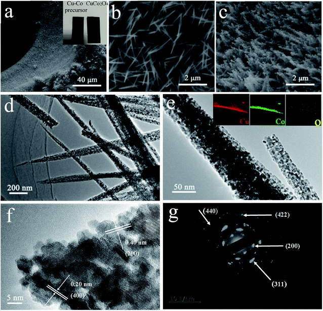
As illustrated in Fig. 1, it is the synthesis process of CuCo2O4 nanoneedle array. A simple hydrothermal procedure was first performed to obtain Cu–Co nanoneedle array precursor (Fig. 1b) vertically grown on conductive substrate (Ni foam), and then an annealing treatment was carried out to form CuCo2O4 nanoneedle array (Fig. 1c). As shown in the optical image, the color of Cu–Co precursor and CuCo2O4 sample turned from pink to black (inset in Fig. 2a). The SEM characterizations were performed to analysis the morphologies for the samples.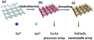 | ||
| Fig. 1 Schematic evolution process of CuCo2O4 nanoneedle array on Ni foam: (a) Ni foam and copper, cobalt sources, (b) Cu–Co precursor array and (c) CuCo2O4 nanoneedle array. | ||
Different morphologies were obtained by adjusting concentration of the solvent. With the increase of the reactant concentration, the samples change from nanosheet-like morphology (Fig. S1a†) to nanowire (Fig. S1b and c†), then to a typical uniform and regular nanoneedle array structure (Fig. 2c), and then to a mixed state of sheet and nanoneedle (Fig. S1d†). In CuCo2O4-12 sample, high density and uniform nanoneedles were vertically grown on Ni foam, ensuring a high utilization for the active material. Fig. 2a, b and c depict SEM images of Cu–Co precursor and CuCo2O4-12, respectively. After annealing, the obtained nanomaterials turn from a typical vertically needle-like morphology to a porous nanoneedles array formed with nanoparticles. The detailed feature and the structures of CuCo2O4 were further revealed in TEM. The diameter of the CuCo2O4 nanoneedle is around 50–80 nm and apparent pores are found on the nanoneedle, as shown in Fig. 2d and e. EDX analysis (insets of Fig. 2e) clearly reveals the existence of Cu, Co, O, along with Ni elements, uniformly distributed throughout the nanoneedle. Nanoneedle structure was made up of sizable amounts of dense pores, which benefits to facilitate the ion and electron transportation into active materials, improving the capacitive performance. As displayed in Fig. 2f, the high-resolution TEM image shows the well-defined interplanar d-spacings of 0.20 nm for (400) plane and 0.40 nm for (200) plane, which indexed well to the feature of CuCo2O4. Moreover, the discontinuous SAED pattern (Fig. 2g) further confirms the CuCo2O4 phase and corroborate the polycrystalline nature of the material.
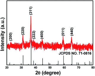
The composition and phase purity of CuCo2O4-12 was characterized by XRD (Fig. 3). To avoid the intense peaks of Ni-foam, we performed the XRD analysis of some powder scrapped off from the Ni foam. Diffraction peaks at 19.0, 31.3, 36.8, 38.6, 44.9, 55.8, 59.3, 65.4 and 77.6° could be well indexed to the (111), (220), (311), (222), (40 0), (422), (511), (440), and (553) planes of cubic CuCo2O4 (JCPDS no. 71-0816). In addition, the absence of other impurity peaks was detected, which confirms the high-purity of the prepared sample.
Further information on the composition and oxidation state of CuCo2O4 nanoneedle array were analyzed by XPS spectrum. The characteristic peaks of C, Ni, Cu, Co and O elements are presented in the full survey spectrum (Fig. 4a). As shown in Fig. 4b, the spectrum of Cu 2p illustrates two main peaks located at 933.3 eV and 953.5 eV, which corresponds to Cu 2p3/2 and Cu 2p1/2. In addition, two satellite of 941.6 and 961.8 eV confirms Cu2+ characteristic.19,20 The peaks of Co 2p spectrum (Fig. 4c) observed at 779.7 eV (Co 2p3/2) and 794.7 eV (Co 2p1/2), along with a splitting of approximately 15 eV, are attributed to the Co2+ and Co3+ states.21 The spectrum of the O 1s (Fig. 4d) displays three different oxygen contributions located at 529.4, 531.0 and 532.2 eV, which are ascribed to typical metal–oxygen (Cu–O or Co–O) bonds,22 the presence of defect sites,23 and the physically and chemically absorbed hydroxyl groups within the surface of CuCo2O4 nanoneedle,24 respectively.
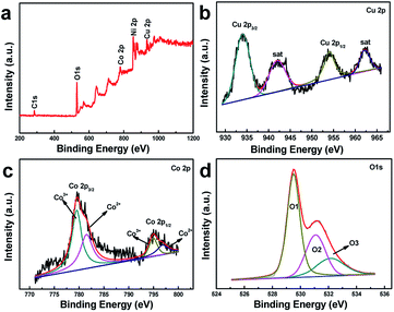 | ||
| Fig. 4 XPS spectra of survey scan (a), Cu 2p (b), Co 2p (c), and O 1s (d) for CuCo2O4 nanoneedle array. | ||
The specific surface area and pore volume of active material play a significant effect on electrochemical properties.25–27 Fig. 5 represents the BET profile of Cu–Co precursor and CuCo2O4 nanoneedle array scrapped off from the Ni foam. The curve of the CuCo2O4 nanoneedle array shows typical IV isotherm, which indicates the unique properties of mesoporous materials.28 The specific surface area of the CuCo2O4 nanoneedle array according to BET measurement is 35.18 m2 g−1, which is much larger than Cu–Co precursor array (10.33 m2 g−1), attributed to the highly porous structure consistent with the SEM and TEM results. In addition, the pore volume of CuCo2O4 nanoneedle array (0.174 cm3 g−1) with average pore diameter of 20.3 nm is much superior to Cu–Co precursor array (0.039 cm3 g−1). The high surface area combined with the abundant mesoporous structure increases active sites and provides fast mass transport, contributing to excellent electrochemical properties.
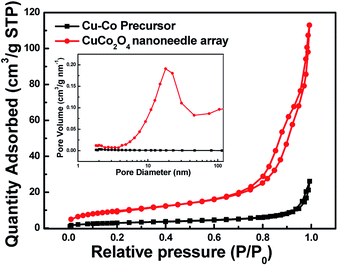 | ||
| Fig. 5 BET isotherm of Cu–Co precursor and CuCo2O4 nanoneedle array (inset is the BJH pore size distribution curves). | ||
3.2 Electrochemical performance
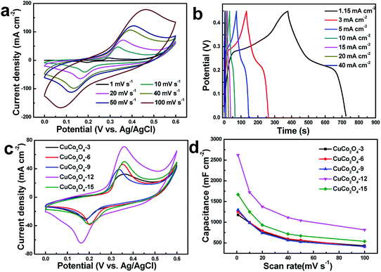
The electrochemical behaviors were first measured in a three-electrode system to evaluate the as-synthesized samples. Cyclic voltammetry (CV) tests within the potential rage between 0 and 0.6 V were obtained. Fig. 6a shows the CV profiles for CuCo2O4-12 electrode at various sweep rates (CVs of other electrodes are shown in Fig. S2†). The obvious pseudocapacitive behavior was demonstrated by the well-defined redox peaks, attributed to the faradaic reaction associated with Co4+/Co3+ and Cu2+/Cu+.29 Moreover, the shape of the CV profiles is almost invariable and symmetrical during different scan rates, indicating the rapid transfer of electrons, high coulombic efficiency and perfect reversibility of the electrode.30,31 The corresponding reaction mechanism of CuCo2O4 during redox reaction in KOH electrolyte is commonly as follows:32| CuCo2O4 + H2O + e− ↔ 2CoOOH + CuOH | (5) |
| CoOOH + OH− ↔ CoO2 + H2O + e− | (6) |
| CuOH + OH− ↔ Cu(OH)2 + e− | (7) |
The galvanostatic charge–discharge (CD) curves were depicted in Fig. 6b. All these curves show nearly symmetric shapes, revealing good electrochemical reversibility. The obvious plateau reveals a more significant battery-type redox behavior, consistent with the CV curves result. Fig. 6c displays the CV comparisons for all as-prepared electrodes attained from different concentration at 20 mV s−1. All curves exhibit the similar pairs of redox peaks. The largest CV integrated area of CuCo2O4-12 electrode obviously indicates highest capacitance than others. To learn more about this, Fig. 6d displays the detailed capacitance versus scan rate for electrode with different reactant concentration. The results reveal that CuCo2O4-12 electrode delivers higher areal capacitance than others at all scan rates. CuCo2O4-12 electrode displays highest capacitance of 2.620 F cm−2 at 1 mV s−1 (CuCo2O4-3: 1.176 F cm−2; CuCo2O4-6: 1.252 F cm−2; CuCo2O4-9: 1.298 F cm−2; CuCo2O4-15: 1.667 F cm−2), demonstrating outstanding charge storage. Meanwhile, CuCo2O4-12 electrode maintains 0.81 F cm−2 at 100 mV s−1 (CuCo2O4-3: 0.430 F cm−2; CuCo2O4-6: 0.407 F cm−2; CuCo2O4-9: 0.412 F cm−2; CuCo2O4-15: 0.537 F cm−2), indicating good rate performance. In addition, the curve of capacitance shows a decreasing trend, which is ascribe to the insufficient diffusion of OH− ions with increasing the scan rate.33 The better electrochemical properties of CuCo2O4-12 electrode are attributed to the mesoporous nanoneedle array architecture, which provides a direct electron transport, facilitates the electrolyte penetration and reduces the interfacial resistance.34,35 The above evidence implies that proper reactant concentration leads to better nanostructure and higher electrochemical performance.
With the optimized nanoarchitecture (CuCo2O4-12), the most remarkable performance improvement is the long-term cycling stability. As shown in Fig. 7a, 70![[thin space (1/6-em)]](https://www.rsc.org/images/entities/char_2009.gif) 000 cycles were tested at 50 mV s−1. Impressively, the capacity retention of the CuCo2O4-12 electrode remains ≈164% after 70
000 cycles were tested at 50 mV s−1. Impressively, the capacity retention of the CuCo2O4-12 electrode remains ≈164% after 70![[thin space (1/6-em)]](https://www.rsc.org/images/entities/char_2009.gif) 000 cycles. The capacitance gets increased at first and keep almost stable in following cycles. The increasing tendency of cycling curve attributed to the activation process and enhanced participated electroactive surface area.36,37 This result is much superior to the reported CuCo2O4 electrodes, for instance, CuCo2O4 nanowires (≈100.9%, 10
000 cycles. The capacitance gets increased at first and keep almost stable in following cycles. The increasing tendency of cycling curve attributed to the activation process and enhanced participated electroactive surface area.36,37 This result is much superior to the reported CuCo2O4 electrodes, for instance, CuCo2O4 nanowires (≈100.9%, 10![[thin space (1/6-em)]](https://www.rsc.org/images/entities/char_2009.gif) 000 cycles),38 CuCo2O4 flowers (≈109%, 2000 cycles),39 CuCo2O4 nanosheets (≈79.7%, 5000 cycles),40 onion-like nanoporous CuCo2O4 hollow spheres (≈93.4%, 5000 cycles),41 and CuCo2O4 nanobelts (≈127%, 1800 cycles)42 in alkaline electrolyte. The capacity retention (exceeds 100%) could be explained in two aspects: the synergistic effects of Cu, Co redox reactions and the hierarchical porous structures of CuCo2O4 materials. At first stage, the electrochemical reactions mainly occurred on the surface of the CuCo2O4 materials. With the cycle increased, the internal active materials were gradually activated, thereby increasing the active site. Meantime, the mesoporous structure of nanoneedles buffers structural deformation, helping maintain the structural stability.43 Moreover, the nanoneedle array structure contribute abundant electrochemical active sites and shorten the diffusion length, enhancing long-term cycling stability. To further understand the fundamental behavior of cycling process, the electrochemical impedance spectroscopy (Fig. 7b) was measured. In EIS spectrum, the x-axis intercept of the curve and the diameter of semicircle stand for the series resistance and charge-transfer resistance. It is observed that electrode after 70
000 cycles),38 CuCo2O4 flowers (≈109%, 2000 cycles),39 CuCo2O4 nanosheets (≈79.7%, 5000 cycles),40 onion-like nanoporous CuCo2O4 hollow spheres (≈93.4%, 5000 cycles),41 and CuCo2O4 nanobelts (≈127%, 1800 cycles)42 in alkaline electrolyte. The capacity retention (exceeds 100%) could be explained in two aspects: the synergistic effects of Cu, Co redox reactions and the hierarchical porous structures of CuCo2O4 materials. At first stage, the electrochemical reactions mainly occurred on the surface of the CuCo2O4 materials. With the cycle increased, the internal active materials were gradually activated, thereby increasing the active site. Meantime, the mesoporous structure of nanoneedles buffers structural deformation, helping maintain the structural stability.43 Moreover, the nanoneedle array structure contribute abundant electrochemical active sites and shorten the diffusion length, enhancing long-term cycling stability. To further understand the fundamental behavior of cycling process, the electrochemical impedance spectroscopy (Fig. 7b) was measured. In EIS spectrum, the x-axis intercept of the curve and the diameter of semicircle stand for the series resistance and charge-transfer resistance. It is observed that electrode after 70![[thin space (1/6-em)]](https://www.rsc.org/images/entities/char_2009.gif) 000 cycles exhibits smaller Rs and Rct (after Rs: 0.44 Ω, Rct: 0.02 Ω; before Rs: 0.58 Ω, Rct: 0.8 Ω), indicating improved electrical conductivity. In addition, the higher slope (after cycling) of the spike line observed at low frequency reveals the more easily ion diffusion. For comparison, Fig. 7c shows the SEM image after 70
000 cycles exhibits smaller Rs and Rct (after Rs: 0.44 Ω, Rct: 0.02 Ω; before Rs: 0.58 Ω, Rct: 0.8 Ω), indicating improved electrical conductivity. In addition, the higher slope (after cycling) of the spike line observed at low frequency reveals the more easily ion diffusion. For comparison, Fig. 7c shows the SEM image after 70![[thin space (1/6-em)]](https://www.rsc.org/images/entities/char_2009.gif) 000 cycles. It is observed that the porous nanoneedle morphology can still be well preserved although regular array architecture has changed. The good electrochemical performance especially excellent stability over thousands of long cycles demonstrates that the optimized electrode is promising for practical applications.
000 cycles. It is observed that the porous nanoneedle morphology can still be well preserved although regular array architecture has changed. The good electrochemical performance especially excellent stability over thousands of long cycles demonstrates that the optimized electrode is promising for practical applications.
 | ||
Fig. 7 (a) Cycling performances, (b) EIS spectra before and after cycle testing, (c) SEM image after 70![[thin space (1/6-em)]](https://www.rsc.org/images/entities/char_2009.gif) 000 cycles of the CuCo2O4-12 electrode. 000 cycles of the CuCo2O4-12 electrode. | ||
3.3 Fabrication of asymmetric supercapacitor
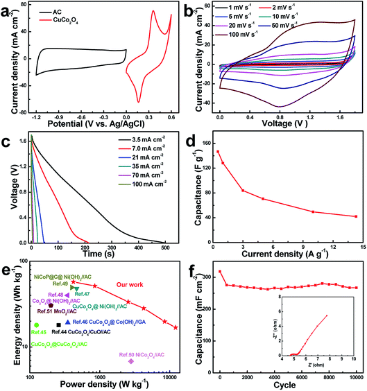
To further demonstrate the practical feasibility of the optimized CuCo2O4-12 electrode, an asymmetric supercapacitor CuCo2O4(+)//AC(−) was constructed with 3 M KOH. The CV profiles of the AC and CuCo2O4-12 electrodes at 20 mV s−1 are displayed in Fig. 8a. Rectangular profile of AC anode reveals the electric double-layer capacitive behavior which is different from the electrochemical feature of CuCo2O4 cathode. Fig. 8b displays that the asymmetric supercapacitor can work efficiently in a large operating voltage for 1.8 V, which is superior to many reported aqueous asymmetric supercapacitors (1.4–1.6 V). As shown, the curves of device maintain a nearly rectangular-like shape in various scan rates, indicating good reversible ability and ideal capacitance behavior. The discharge curves (Fig. 8c) show that the potential decay is linear at the beginning and then slows down. The corresponding specific capacitances versus current densities are presented in Fig. 8d. Notably, the asymmetric supercapacitor can reach 146 F g−1 (0.5 A g−1) and retain 42 F g−1 with increasing to 14.3 A g−1, implying good rate ability.Ragone plots are important for device application. The Ragone plots of CuCo2O4(+)//AC(−) device based on CD curves are shown in Fig. 8e. The asymmetric supercapacitor delivers a maximum energy density of 57 W h kg−1 at 420 W kg−1, which outperforms those of aqueous asymmetric devices reported recently, such as AC//CuCo2O4/CuO (18 W h kg−1),44 CuCo2O4@CuCo2O4//AC (18 W h kg−1),45 CuCo2O4@Co(OH)2//GA (19.2 W h kg−1),46 AC//CuCo2O4@Ni(OH)2 (48 W h kg−1),47 AC//Co3O4@Ni(OH)2 (40 W h kg−1),48 AC//NiCoP@C@Ni(OH)2 (49.5 W h kg−1),49 NiCo2O4//AC (6.8 W h kg−1),50 and AC//MnO2 (30.6 W h kg−1).51 Moreover, the device remains 16.8 W h kg−1 at 12![[thin space (1/6-em)]](https://www.rsc.org/images/entities/char_2009.gif) 142 W kg−1, revealing a well power ability. Additionally, the cycling performance of the as-fabricated asymmetric supercapacitor was performed at 50 mV s−1. After 10
142 W kg−1, revealing a well power ability. Additionally, the cycling performance of the as-fabricated asymmetric supercapacitor was performed at 50 mV s−1. After 10![[thin space (1/6-em)]](https://www.rsc.org/images/entities/char_2009.gif) 000 cycles (Fig. 8f), the capacitance shows 83.9% retention of initial capacitance, implying excellent cycling performance, much better than the reported asymmetric devices, for instance, MnO2@carbon spheres//nitrogen-doped activated carbon (≈74.4%, 1000 cycles),52 Co3O4@Ni3S2//AC (≈61.5%, 1000 cycles),53 CoMn-layered double hydroxides//Fe3O4@N-doped carbon (≈80%, 5000 cycles),54 and ZnO nanoflakes//AC (≈75.6%, 8000 cycles).55 The EIS testing of the device (inset in Fig. 8f) was further performed to understand the electrochemical behavior. The x-axis intercept of the curve (Rs) and the diameter of semicircle (Rct) are 4.7 Ω and 0.55 Ω, respectively, which reveals a small intrinsic resistance of the electrochemical system and rapid transport kinetics of electron. Furthermore, the steep slope of the linear portion indicates an efficient ionic diffusion. The above results endow great application potentials of our device in electrochemical capacitor.
000 cycles (Fig. 8f), the capacitance shows 83.9% retention of initial capacitance, implying excellent cycling performance, much better than the reported asymmetric devices, for instance, MnO2@carbon spheres//nitrogen-doped activated carbon (≈74.4%, 1000 cycles),52 Co3O4@Ni3S2//AC (≈61.5%, 1000 cycles),53 CoMn-layered double hydroxides//Fe3O4@N-doped carbon (≈80%, 5000 cycles),54 and ZnO nanoflakes//AC (≈75.6%, 8000 cycles).55 The EIS testing of the device (inset in Fig. 8f) was further performed to understand the electrochemical behavior. The x-axis intercept of the curve (Rs) and the diameter of semicircle (Rct) are 4.7 Ω and 0.55 Ω, respectively, which reveals a small intrinsic resistance of the electrochemical system and rapid transport kinetics of electron. Furthermore, the steep slope of the linear portion indicates an efficient ionic diffusion. The above results endow great application potentials of our device in electrochemical capacitor.
4. Conclusions
In summary, the mesoporous CuCo2O4 nanoneedle array was successfully fabricated via a facile and controllable hydrothermal technique, for which the structure and electrochemical performance can be controlled by simply adjusting reactant concentration. Meantime, the optimized CuCo2O4-12 electrode exhibits a superb storage capacity of 2.62 F cm−2 (1747 F g−1) with remarkable cyclic stability (164% retention over 70![[thin space (1/6-em)]](https://www.rsc.org/images/entities/char_2009.gif) 000 cycles). Moreover, the fabricated CuCo2O4//AC asymmetric supercapacitor achieved an ultrahigh energy density of 57 W h kg−1 and excellent cyclic stability retained 83.9% after 10
000 cycles). Moreover, the fabricated CuCo2O4//AC asymmetric supercapacitor achieved an ultrahigh energy density of 57 W h kg−1 and excellent cyclic stability retained 83.9% after 10![[thin space (1/6-em)]](https://www.rsc.org/images/entities/char_2009.gif) 000 cycles. These outstanding performances indicate that the optimized mesoporous CuCo2O4 nanoneedle array electrode holds great potential in energy storage applications.
000 cycles. These outstanding performances indicate that the optimized mesoporous CuCo2O4 nanoneedle array electrode holds great potential in energy storage applications.
Conflicts of interest
There are no conflicts to declare.Acknowledgements
This work was supported by the National Natural Science Foundation of China (No. 51802233), the Natural Science Foundation of Hubei Province of China (No. 2018CFB154, 2018CFA022) and Chongqing Key Laboratory for Advanced Materials & Technologies of Clean Energies (No. JJNY201906).Notes and references
- W. Raza, F. Ali, N. Raza, Y. Luo, K.-H. Kim, J. Yang, S. Kumar, A. Mehmood and E. E. Kwon, Nano Energy, 2018, 52, 441–473 CrossRef CAS.
- J. Lin, H. Jia, H. Liang, S. Chen, Y. Cai, J. Qi, C. Qu, J. Cao, W. Fei and J. Feng, Adv. Sci., 2018, 5, 1700687 CrossRef PubMed.
- X. Zhang, S. Deng, Y. Zeng, M. Yu, Y. Zhong, X. Xia, Y. Tong and X. Lu, Adv. Funct. Mater., 2018, 28, 1805618 CrossRef.
- X. Wang, B. Liu, R. Liu, Q. Wang, X. Hou, D. Chen, R. Wang and G. Shen, Angew. Chem., Int. Ed., 2014, 53, 1849–1853 CrossRef CAS PubMed.
- D. Chen, D. Pang, S. Zhang, H. Song, W. Zhu and J. Zhu, Electrochim. Acta, 2020, 330, 135326 CrossRef CAS.
- X. Li, Z. Wang, Y. Qiu, Q. Pan and P. Hu, J. Alloys Compd., 2015, 620, 31–37 CrossRef CAS.
- M. Cakici, K. R. Reddy and F. Alonso-Marroquin, Chem. Eng. J., 2016, 309, 151–158 CrossRef.
- X. Xiong, D. Ding, D. Chen, G. Waller, Y. Bu, Z. Wang and M. Liu, Nano Energy, 2015, 11, 154–161 CrossRef CAS.
- Q. Gao, J. Wang and J. Wang, J. Alloys Compd., 2019, 789, 193–200 CrossRef CAS.
- G. Xiong, P. He, D. Wang, Q. Zhang, T. Chen and T. S. Fisher, Adv. Funct. Mater., 2016, 26, 5460–5470 CrossRef CAS.
- W. Fu, L. Long, M. Wang, Y. Yao, N. Wei, M. Yan, G. Yin, X. Liao, Z. Huang and X. Chen, J. Alloys Compd., 2015, 631, 82–85 CrossRef CAS.
- A. Pendashteh, S. E. Moosavifard, M. S. Rahmanifar, Y. Wang, M. F. El-Kady, R. B. Kaner and M. F. Mousavi, Chem. Mater., 2015, 27, 3919–3926 CrossRef CAS.
- A. T. Aqueel Ahmed, B. Hou, H. S. Chavan, Y. Jo, S. Cho, J. Kim, S. M. Pawar, S. Cha, A. I. Inamdar, H. Kim and H. Im, Small, 2018, 14, e1800742 CrossRef PubMed.
- F. S. Omar, A. Numan, N. Duraisamy, M. M. Ramly, R. Kasi and R. T. Subramaniam, Electrochim. Acta, 2017, 227, 41–48 CrossRef CAS.
- L. Abbasi and M. Arvand, Appl. Surf. Sci., 2018, 445, 272–280 CrossRef CAS.
- Y. Wang, D. Yang, J. Lian, T. Wei and Y. Sun, J. Alloys Compd., 2018, 741, 527–531 CrossRef CAS.
- B. Fang, J. H. Kim, M.-S. Kim, A. Bonakdarpour, A. Lam, D. P. Wilkinson and J.-S. Yu, J. Mater. Chem., 2012, 22, 19031–19038 RSC.
- Y. Z. Wei, B. Fang, S. Iwasa and M. Kumagai, J. Power Sources, 2005, 141, 386–391 CrossRef CAS.
- S. E. Moosavifard, S. Fani and M. Rahmanian, Chem. Commun., 2016, 52, 4517–4520 RSC.
- R. BoopathiRaja, M. Parthibavarman and A. Nishara Begum, Vacuum, 2019, 165, 96–104 CrossRef CAS.
- F. Saleki, A. Mohammadi, S. E. Moosavifard, A. Hafizi and M. R. Rahimpour, J. Colloid Interface Sci., 2019, 556, 83–91 CrossRef CAS PubMed.
- S. K. Kaverlavani, S. E. Moosavifard and A. Bakouei, J. Mater. Chem. A, 2017, 5, 14301–14309 RSC.
- X.-F. Lu, D.-J. Wu, R.-Z. Li, Q. Li, S.-H. Ye, Y.-X. Tong and G.-R. Li, J. Mater. Chem. A, 2014, 2, 4706–4713 RSC.
- C. Jin, Y. Cui, G. Zhang, W. Luo, Y. Liu, Y. Sun, Z. Tian and W. Zheng, Chem. Eng. J., 2018, 343, 331–339 CrossRef CAS.
- B. Fang, M. Kim, S. Q. Fan, J. H. Kim, D. P. Wilkinson, J. Ko and J. S. Yu, J. Mater. Chem., 2011, 21, 8742–8748 RSC.
- B. Fang, J. H. Kim, M. S. Kim and J. S. Yu, Acc. Chem. Res., 2013, 46, 1397–1406 CrossRef CAS PubMed.
- W. B. Hua, X. D. Guo, Z. Zheng, Y. J. Wang, B. H. Zhong, B. Fang, J. Z. Wang, S. L. Chou and H. Liu, J. Power Sources, 2015, 275, 200–206 CrossRef CAS.
- J. Xie, Z. Zhan, S. Zhang, G. Li, H. Xia, Y. Yang and J. Xiong, Mater. Lett., 2018, 226, 30–33 CrossRef CAS.
- S. Kamari Kaverlavani, S. E. Moosavifard and A. Bakouei, Chem. Commun., 2017, 53, 1052–1055 RSC.
- Y. Zhu, X. Pu, W. Song, Z. Wu, Z. Zhou, X. He, F. Lu, M. Jing, B. Tang and X. Ji, J. Alloys Compd., 2014, 617, 988–993 CrossRef CAS.
- Y. Tang, Y. Liu, S. Yu, Y. Zhao, S. Mu and F. Gao, Electrochim. Acta, 2014, 123, 158–166 CrossRef CAS.
- S. Vijayakumar, S. Nagamuthu and G. Muralidharan, ACS Sustainable Chem. Eng., 2013, 1, 1110–1118 CrossRef CAS.
- R. Suresh Babu, R. Vinodh, A. L. F. de Barros, L. M. Samyn, K. Prasanna, M. A. Maier, C. H. F. Alves and H.-J. Kim, Chem. Eng. J., 2019, 366, 390–403 CrossRef CAS.
- J. H. Kim, B. Fang, M. Kim and J. S. Yu, Catal. Today, 2009, 146, 25–30 CrossRef CAS.
- B. Fang, S. Q. Fan, J. H. Kim, M. S. Kim, M. Kim, N. K. Chaudhari, J. Ko and J. S. Yu, Langmuir, 2010, 26, 11238–11243 CrossRef CAS PubMed.
- S. Vijayakumar, S.-H. Lee and K.-S. Ryu, Electrochim. Acta, 2015, 182, 979–986 CrossRef CAS.
- X. Tang, H. Li, Z. H. Liu, Z. Yang and Z. Wang, J. Power Sources, 2011, 196, 855–859 CrossRef CAS.
- L. Liao, H. Zhang, W. Li, X. Huang, Z. Xiao, K. Xu, J. Yang, R. Zou and J. Hu, J. Alloys Compd., 2017, 695, 3503–3510 CrossRef CAS.
- S. Vijayakumar, S. Nagamuthu and K.-S. Ryu, Electrochim. Acta, 2017, 238, 99–106 CrossRef CAS.
- S. Liu, K. S. Hui and K. N. Hui, ACS Appl. Mater. Interfaces, 2016, 8, 3258–3267 CrossRef CAS PubMed.
- A. A. Ensafi, S. E. Moosavifard, B. Rezaei and S. K. Kaverlavani, J. Mater. Chem. A, 2018, 6, 10497–10506 RSC.
- B. Sydulu Singu, R. Kuchi, P. Cao Van, D. Kim, K. Ro Yoon and J. Ryul Jeong, ChemNanoMat, 2019, 5, 1398–1407 CrossRef CAS.
- B. Fang, H. Zhou and I. Honma, J. Phys. Chem. B, 2006, 110, 4875–4880 CrossRef CAS PubMed.
- A. Shanmugavani and R. K. Selvan, Electrochim. Acta, 2016, 188, 852–862 CrossRef CAS.
- Y. Zhang, J. Xu, Y. Zheng, Y. Zhang, X. Hu and T. Xu, RSC Adv., 2017, 7, 3983–3991 RSC.
- Y. Zhang, H. Liu, M. Huang, J. M. Zhang, W. Zhang, F. Dong and Y. X. Zhang, ChemElectroChem, 2017, 4, 721–727 CrossRef CAS.
- Z. Zhan, S. Chen, J. Xie, Y. Yang and J. Xiong, J. Alloys Compd., 2017, 722, 928–937 CrossRef CAS.
- X. Bai, Q. Liu, J. Liu, H. Zhang, Z. Li, X. Jing, P. Liu, J. Wang and R. Li, Chem. Eng. J., 2017, 315, 35–45 CrossRef CAS.
- Q. Zong, H. Yang, Q. Wang, Q. Zhang, Y. Zhu, H. Wang and Q. Shen, Chem. Eng. J., 2019, 361, 1–11 CrossRef CAS.
- R. Ding, L. Qi, M. Jia and H. Wang, Electrochim. Acta, 2013, 107, 494–502 CrossRef CAS.
- J.-G. Wang, Y. Yang, Z.-H. Huang and F. Kang, Carbon, 2013, 61, 190–199 CrossRef CAS.
- J. Wen, X. Chen, M. Huang, W. Yang and J. Deng, J. Chem. Sci., 2019, 132, 1–11 Search PubMed.
- X. X. Liu, R. Wu, Y. Wang, S. H. Xiao, Q. He, X. B. Niu, D. J. Blackwood and J. S. Chen, Electrochim. Acta, 2019, 311, 221–229 CrossRef CAS.
- J. Zhou, S. Xu, L. Ni, N. Chen, X. Li, C. Lu, X. Wang, L. Peng, X. Guo, W. Ding and W. Hou, J. Power Sources, 2019, 438, 227047 CrossRef CAS.
- A. Ali, M. Ammar, M. Ali, Z. Yahya, M. Y. Javaid, S. U. Hassan and T. Ahmed, RSC Adv., 2019, 9, 27432–27438 RSC.
Footnote |
| † Electronic supplementary information (ESI) available. See DOI: 10.1039/d0ra03771k |
| This journal is © The Royal Society of Chemistry 2020 |

