 Open Access Article
Synthesis and characterization of a novel TEMPO@FeNi3/DFNS–laccase magnetic nanocomposite for the reduction of nitro compounds
Shima Saberia,
Rahele Zhiani *b,
Jamshid Mehrzad*a and
Alireza Motavalizadehkakhky
 b
b
aDepartment of Biochemistry, Faculty of Science, Islamic Azad University, Neyshabur Branch, Neyshabur, Iran. E-mail: mehrzadjam@yahoo.com
bDepartment of Chemistry, Faculty of science, Islamic Azad University, Neyshabur Branch, Neyshabur, Iran. E-mail: R_zhiani2006@yahoo.com
First published on 21st July 2020
Abstract
Water is an essential substance for life on earth and for all living things. Plants and animals need almost pure water to live; if it is contaminated with harmful chemicals and micro organisms, it will be impossible for them to survive. This study has tried to investigate the performance of catalyst to reduce nitro-aromatic combinations in the attendance of NaBH4 solution duo to the hydrogen source. TEMPO@FeNi3/DFNS–laccase MNPs was prepared, and its features were reviewed using SEM, TEM, XRD, TGA, VSM, AFM, and FTIR. Then, its strength as a nanocatalyst for removal of nitro-aromatic combinations was tested in contact time, initial concentration, the effects of pH and nanocatalyst amount was study. The results of this research proved that TEMPO@FeNi3/DFNS–laccase MNPs has a good return in removal of nitro-aromatic combinations, as its easy synthesis and reliable recovery.
Introduction
Water pollution has become a serious global concern, which threatens the entire biosphere and influences the lives of many individuals around the globe. Different kinds of illnesses are caused by this pollution and many people die every year due to diseases caused by polluted water. Nitroarene hydrogenation is one of the most effective ways for producing aromatic amines. The amine group is often an important mediator for manufacturing many drugs, organic chemicals, rubber materials, photographic, polymers and dyes.1 Many strategies have been developed for decreasing a nitro precursor such as metal/acid reduction,2–4 hydrogenation of catalytic,5 Hydrogenation at homogeneous catalytic transition,6 and hydrogenation at heterogeneous catalytic transfer.7,8 Nonetheless, these processes have some significant disadvantages; for instance, metal/acid system has demonstrated poor selectivity and this technique is ecologically hazardous; besides, hydrogenation of catalytic is not favored because of applying H2 gas at high temperature, it is not easy to separate the homogeneous or heterogeneous catalytic transfer hydrogenation from the ultimate product.9,10 Accordingly, it is important to discover new catalysts for hydrogenation of nitroarenes under favorable situations.Various researches have reported the usage of supported laccase for the preparation of materials, however, the application of expensive intermediate reagents such as 2,2,6,6-tetramethyl-1-piperidinyloxy (TEMPO) are unavoidable for laccase catalyzed reactions. For a large-scale reaction, the recycling of laccase and the mediator is in favor.11 The usage of porous material in co-immobilizing both laccase and the mediator is found to be effective as both species can be found in the individual cavity of the support.12 For this application, a magnetic material known as FeNi3 alloy is extensively used for its excellent permeability, magnetic saturation and experience minimal energy loss. The concerns that arise for the synthesis of FeNi3 nanomaterials are the risks possessed by the individual metal. It is especially alarming as nickel can be an allergen that causes dermatitis and possesses carcinogenic properties. Despite the concerns, FeNi3 has not been reported to be harmful. The problem that persist is the instability of magnetic particle for a long-term application as FeNi3 is highly chemically reactive and can go through oxidation in air. This contributes to the loss of magnetic properties and dispersion.13–19
In the recent years, the utilize of surfactant over soft templating caused the production of mesoporous silica along with dendrimeric silica fibers morphology (DFNS). For adsorption and catalysis approaches as support material, silica having this morphology are analyzed. For reactants for accessing the functional materials more properly, the appearance radial widening of these silicas possesses higher surface area. Moreover, DFNS possesses intrinsic mesoporous characteristics, exhibits high activity and thermally stable. The production of DFNS needs microemulsion method that involves water, surfactant, and oil. In addition, the morphology of DFNS and particle size may be varied considering co-surfactant and different co-solvents.20–26
A bifunctional hybrid catalyst is synthesized by co-immobilizing laccase and TEMPO into the cavities of magnetic DFNS. In consideration on the environmental impact caused by antibiotic residuals and the high oxidation of rate in the removal of organic contaminants, this research is aimed at investigating the photocatalytic efficiency of the bifunctional hybrid catalyst synthesized for reduction of 4-NP to 4-AP from aqueous environment.
Experimental
General procedure for the preparation of FeNi3 MNPs
The procedure involved in the preparation of FeNi3 MNPs involved dissolving 0.01 mol FeCl2·4H2O and 0.03 mol NiCl2·6H2O into 300 mL of distilled water and the subsequent addition of 1.0 g of polyethylene glycol (PEG, MW 6000). To achieve the pH range of 12 ≤ pH ≤ 13, sodium hydroxide (NaOH) were added to the solution. Next, hydrazine hydrate (N2H4·H2O) at 80% concentration were added to the suspension in varied quantity. The suspension was left to react continuously for 24 h at room temperature. The pH of the suspension was maintained at 12 ≤ pH ≤ 13 with periodical dosing of NaOH. After that, the solid phase of resultant mixture was filtered to obtain a black colored FeNi3 MNPs and rinsed with ionized water multiple times.27General procedure for the preparation of FeNi3/SiO2 MNPs
An aqueous solution containing 80 mL of ethanol, 20 mL of ionized water and 2.0 mL of 28 wt% concentrated ammonia aqueous solution (NH3·H2O) was prepared. 0.02 mol of FeNi3 MNPs were dispersed in the mixture and 0.20 g of tetraethyl orthosilicate (TEOS) were added subsequently. The mixture was vigorously stirred for 24 h. The solid phase of the resultant mixture was filtered and washed several times before being dried in atmospheric condition at 60 °C.27General procedure for the preparation of FeNi3/DFNS MNPs
Solution A was prepared with the addition of 30 mL aqueous solution containing 0.3 g urea and dispersion of 0.25 g of FeNi3/SiO2. The mixture was placed in an ultrasonic bath for 1 h. Solution B was prepared with the addition of 0.5 g cetylpyridinium bromide (CPB) into 0.75 mL of n-pentanol and 30 mL of cyclohexane. Solution A and solution B were mixed and stirred at room temperature and 1.25 g TEOS was added in a drop wise manner. The mixture was continuously stirred for 1 h at room temperature and placed in an oven at 120 °C for 5 h to incite reaction. The completed reaction was cooled to room temperature before applying a strong magnetic suction for the isolation of FeNi3/DFNS core–shell microspheres. The solid phase was then washed several times with water and acetone. The washed solid were dried in a drying oven at 40 °C overnight and calcined at 550 °C for 5 h in atmospheric condition.27General procedure for the preparation of FeNi3/DFNS/GMSI MNPs
A mixture was prepared by mixing 200 mg of FeNi3/DFNS in 20 mL of THF followed by the addition of 20 mmol of NaH via ultrasonication. After that, 22 mmol of (3-glycidyloxypropyl)trimethoxysilane were added into the mixture at room temperature and stirred for 16 h at 50 °C. The resultant mixture was filtered and washed with ethanol and deionized water. The filtered solids were then dried in vacuum condition at 50 °C for 3 h.28General procedure for the preparation of TEMPO@FeNi3/DFNS–laccase MNPs
Glycidyloxypropyl were used for the activation of FeNi3/DFNS (100 mg). This was then added to a mixture containing 10 mL of acetate buffer at 0.1 M and pH of 4.5, laccase and 4-hydroxy-TEMPO. The mixture is stirred at 120 rpm for a few hours. The resultant nanoparticles containing co-immobilized laccase and TEMPO were filtered and rinsed with acetate buffer multiple times. The filtered nanoparticles were kept and store under 4 °C.28General procedure for reducing nitro compounds
Suspension of NaBH4 (1.5 mmol) in H2O (5 mL) was added to nitro compound (1 mmol) and stirring was applied at 50 °C in the presence of TEMPO@FeNi3/DFNS–laccase (15 mg) in water. TLC was applied for monitoring the reaction progress. After the end of the reaction, the catalyst was removed and eluted with ethanol. Ethyl acetate was applied to extract the reaction mixture and dried with Na2SO4. The product was purified by column chromatography using hexane–ethyl acetate as solvent system in various concentrations to get the pure compound.Results and discussion
The preparation of magnetic DFNS were done in accordance to previously established procedures and then functionalized with (3-glycidyloxypropyl)trimethoxysilane. The chemical process involved in the construction of co-immobilized TEMPO and enzyme is shown in Scheme 1.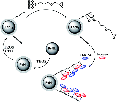 | ||
| Scheme 1 The process of co-immobilization of laccase and TEMPO onto glycidyloxypropyl-functionalized FeNi3/DFNS nanoparticles. | ||
TEM and FE-SEM were used for the morphological and structural characterization of the FeNi3/DFNS, and TEMPO@FeNi3/DFNS–laccase MNPs. The images from TEM and FE-SEM showed spherical shaped solid composed of fibers. It is observed in Fig. 1a that FeNi3/DFNS has a core made from FeNi3 particle with nonporous silica layer and silica fibres. A uniform and monodispersed as-prepared magnetic core–shell fibrous silica material FeNi3/DFNS with fibrous structure were also observed. Fig. 1a and c displayed highly textured FeNi3/DFNS samples containing spheres of uniform size (∼300 nm) with wrinkled radial structure. The wrinkled fibres with an approximate thickness of ∼8.5 nm is observed to be a three-dimensional radial extension from the center of the sphere. Also, cone-shaped open pores were formed as wrinkled radial structure overlapped on each other. Nevertheless, mass transfer of reactants was enhanced with the formation open hierarchical channel structures and fibers due to increase accessibility to active sites. TEM and FE-SEM images also showed that there are no morphological changes were experienced with modified FeNi3/DFNS.
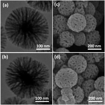 | ||
| Fig. 1 TEM images of FeNi3/DFNS MNPs (a); TEMPO@FeNi3/DFNS–laccase MNPs (b); FE-SEM images of FeNi3/DFNS MNPs (c); TEMPO@FeNi3/DFNS–laccase MNPs (d). | ||
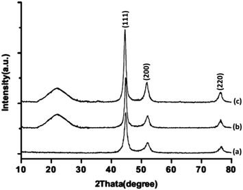
Fig. 2 illustrates the powder X-ray diffraction patterns of FeNi3, FeNi3/DFNS, and TEMPO@FeNi3/DFNS–laccase MNPs respectively. Prominent diffraction peaks were observed at 111, 200 and 220 for all samples. The XRD patterns obtained is in good agreement to report in the JCPDS card (no. 19-0629) for standard FeNi3 sample as shown in Fig. 2a. A broad amorphous peak is observed in Fig. 2b which corresponded to the amorphous silica in FeNi3/DFNS core–shell nanoparticles. XRD pattern shown in Fig. 2c for TEMPO@FeNi3/DFNS–laccase MNPs were determined to be normal and had experienced no changes.
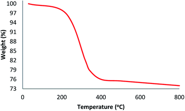
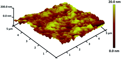
TGA analysis of TEMPO@FeNi3/DFNS–laccase MNPs were illustrated in Fig. 3. The weight loss experienced below 150 °C were a consequence of the removal of physically and chemically absorbed solvent from the surface of the TEMPO@FeNi3/DFNS–laccase material. A 23.2 wt% loss was experienced around 250–450 °C which corresponded to the organic group derivatives. The weight decrement at this temperature is attributed to the oxidation of TEMPO and laccase at around 180–350 °C. In fact, the remaining mass after the organic decomposition in TEMPO@FeNi3/DFNS–laccase MNPs is due to the DFNS NPs. Atomic force microscopy (AFM) were utilized to determine the surface roughness of TEMPO@FeNi3/DFNS–laccase MNPs. The resultant topographic images observed in Fig. 4 showed that decreasing T/W is accompanied by greater height region represented by bright yellowish color. This suggested the increment in surface roughness of the catalyst.
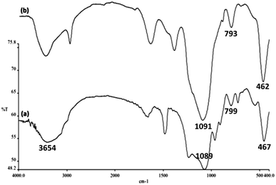
Surface silanol, hydroxyl and phosphate groups were determined to be present in FeNi3/DFNS, and aminofunctionalized FeNi3/DFNS nanoparticles via FTIR analyses as shown in Fig. 5. For FeNi3/DFNS, presence of Si–O–Si unsymmetrical stretching and OH are evident in the broad absorption bands at 1089 cm−1 and 3654 cm−1 respectively. Symmetrical stretching of Si–O–Si and bending is represented by the peaks observed at 799 cm−1 and 467 cm−1 as shown in Fig. 5a. This signified that GMSI is successfully grafted on DFNS surface. Bands around 1091, 793 and 462 cm−1 were exhibited by GMSI–FeNi3/DFNS composite. The occurrence of –OH and –NH stretching vibrations are characterized by a strong and broad absorption band at 3000–3550 cm−1. Peak appeared at 2930 cm−1 are due to the stretching of the C–H aliphatic group (Fig. 5b).
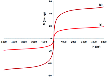
Vibrating sample magnetometer (VSM) are utilized or the specification of the nanoparticles magnetic characteristics by the magnetization curves of the archived nanocomposite considered at the temperature of 300 K. Fig. 6 shows that no residual magnetism was specified, so paramagnetic properties were exhibited using the nanocomposites. Value of saturation magnetization of 51.2 and 16.3 emu g−1 are specified for FeNi3 and TEMPO@FeNi3/DFNS–laccase MNPs, respectively. External magnetic field as well as the ability for rapid redispersion on removal of magnetic field has been introduced as a properties of paramagnetic nanocomposites along with high magnetization amounts. Therefore, the resultant nanocomposite showed proper magnetic responsivity proposing potential application in the cases of targeting and separation.
TEMPO@FeNi3/DFNS–laccase and BET specific surface area for FeNi3/DFNS are specified through nitrogen physisorption analysis. It is determined to be 340 and 652 m2 g−1, respectively. TEMPO@FeNi3/DFNS–laccase reduced in surface area compared with FeNi3/DFNS due to the supporting of laccase and TEMPO in the FeNi3/DFNS. In addition, reducing surface area is more clear in TEMPO@FeNi3/DFNS–laccase MNPs due to poor bicontinuous concentric TEMPO as well as laccase morphology of the nanocatalyst. The attendance of mesopores in FeNi3/DFNS was proved to the attendance of IV isotherm as well as H1-type hysteresis loop. To calculate pore size distribution by BJH approach, the desorption branch of nitrogen isotherm was utilized. Table 1 shows that corresponding pore size distribution presented a narrow pore size distribution peaked at 11 nm (refer to Table 1). The high mesopore size of FeNi3/DFNS by great capacity can load TEMPO as well as laccase, which have relative large molecular size.
| Catalysts | SBET (m2 g−1) | Va (cm3 g−1) | DBJH (nm) |
|---|---|---|---|
| FeNi3/DFNS | 652 | 3.4 | 11 |
| TEMPO@FeNi3/DFNS–laccase | 340 | 1.9 | 6 |
The catalytic performance of the new nanocatalyst TEMPO@FeNi3/DFNS–laccase was examined to decrease fragrant nitro compounds. To improve the reaction conditions, the reduction reaction of para-nitrophenol within the attendance of NaBH4 as the hydrogen source was considered as a model reaction. Initially, the solvent effect and molar ratio of hydrogen sources on the model reaction were studied (Table 2, entries 1–13). According to our findings, water was the simplest solvent for the model reaction when 1.5 mmol NaBH4 was applied; thus, the output was gotten by 99% yield (Table 2, entry 2). Increasing the amount of NaBH4 from 1.0 mmol to 2.5 mmol resulted in an improvement within the rate of para-nitrophenol reduction (Table 2, entries 1–4). Reduction process was very slow in aprotic solvents like CH2Cl2, CH3CN, DMSO (Table 2, entries 10–12) and non-polar solvent like n-hexane (Table 2, entry 13). Using CH3OH, H2O, EtOH as protic solvents was the most appropriate procedure for this catalytic system (Table 2, entries 8 and 9); H2O was chosen for the nitroarene reduction because it is cheap, harmless, and ecologically green solvent.
| Entry | Source of hydrogen | Solvent | Time (min) | Yield (%) |
|---|---|---|---|---|
| 1 | NaBH4 (1.0 mmol) | H2O | 5 | 39 |
| 2 | NaBH4 (1.5 mmol) | H2O | 5 | 99 |
| 3 | NaBH4 (2.0 mmol) | H2O | 5 | 99 |
| 4 | NaBH4 (2.5 mmol) | H2O | 5 | 99 |
| 5 | NaBH4 (1.5 mmol) | H2O | 3 | 99 |
| 6 | NaBH4 (1.5 mmol) | H2O | 2 | 99 |
| 7 | NaBH4 (1.5 mmol) | H2O | 1 | 63 |
| 8 | NaBH4 (1.5 mmol) | CH3OH | 2 | 90 |
| 9 | NaBH4 (1.5 mmol) | EtOH | 2 | 82 |
| 10 | NaBH4 (1.5 mmol) | CH2Cl2 | 2 | 30 |
| 11 | NaBH4 (1.5 mmol) | CH3CN | 2 | 36 |
| 12 | NaBH4 (1.5 mmol) | DMSO | 2 | 27 |
| 13 | NaBH4 (1.5 mmol) | n-Hexane | 2 | 12 |
The influence of catalyst content on the model reaction was explored. There was no advancement within the decrease of nitro-aromatic combinations, in the absence of neither catalyst nor TEMPO@FeNi3/DFNS–laccase MNPs. Fig. 7 shows that, increasing the quantity of catalyst from 1 to 15 mg per mmol of substrate leads to increased reaction efficiency; thus, the maximum yield (99%) has been obtained from a 15 mg catalyst attendance. The findings fit well with significant increase in the number of active positions.
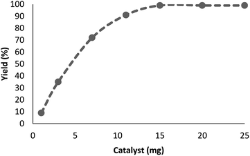 | ||
| Fig. 7 Effect of increasing amount of TEMPO@FeNi3/DFNS–laccase MNPs on yield of reduction of para-nitrophenolin. | ||
The catalytic efficiency of TEMPO@FeNi3/DFNS–laccase MNPs by using the decrease of 4-NP in 4-AP under the existence of NaBH4, which could be a probe reaction. Using UV-vis spectroscopy, the expansion method with time of reaction within the case of the reduction of 4-NP to 4-AP was evaluated. As observed in Fig. 8a, 4-NP solution indicates a correct absorption peak in 300 nm, which is red-shifted to 400 nm, dramatically. Using 15 mg TEMPO@FeNi3/DFNS–laccase MNPs within the system led to decrease the height severity of 4-NP (in 400 nm) with the simultaneous increment within the peaks related to 4-AP at 300 nm. The response swiftly occurred with the conversion of 99% in a very time interval of about 120 s (Fig. 8b).
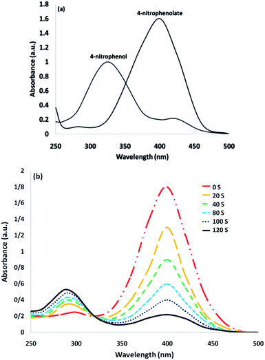 | ||
| Fig. 8 UV-vis spectra of (a) 4-NP before and after adding NaBH4 solution; and (b) the consecutive reduction of 4-NP to 4-AP. | ||
The reaction conversion is measured with Ct/C0, obtained the relative strength of UV-vis absorbance (At/A0) (at 400 nm). Ct shows the concentration of 4-NP at the interval (t). C0 indicates the primary concentration. Fig. 9 shows the mean value of the reaction conversions by standard deviation. Fig. 10 illustrates the linear correlation between the time of reaction. ln(Ct/C0) shows that the reaction was first-order considering that the reduction of 4-NP. Fig. 10 indicates the linear correlation among reaction time and ln(Ct/C0) considering that the 4-NP reduction is first-order. Nevertheless, the kinetic relation of this catalytic reduction reaction can be illustrated as ln(Ct/C0) = −kt. Here, t shows the reaction time and k shows the apparent first-order rate constant (s−1). The k, reaction rate constant, be estimated 0.944 s−1 in the case of the TEMPO@FeNi3/DFNS–laccase MNPs catalyzed 4-NP reduction. The activity factor, k′ = k/M, is showed, for a quantitative comparison that introduced as the ratio of k to the weight of the catalyst utilized. In addition, M indicates the total mass of the catalyst that was utilized during the reaction. Hence, the reaction rate constants per unit mass was estimated to be 9.44 s−1 g−1 in case of the reduction of 4-NP.
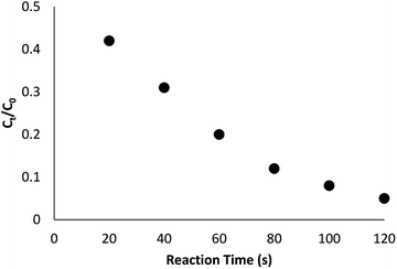 | ||
| Fig. 9 The scheme of Ct/C0 against reaction time for the reduction of 4-NP over TEMPO@FeNi3/DFNS–laccase MNPs. | ||
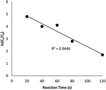 | ||
| Fig. 10 The scheme of ln(Ct/C0) against reaction time for the reduction of 4-NP over TEMPO@FeNi3/DFNS–laccase MNPs. | ||
As Table 3 shows, we used the enhanced situations for transforming of nitro aromatic comprising various functional groups into the intended amino compounds (Table 3, entries 1–12). Table 3 findings suggest that electrons with substituents for drawing/donating have no extraordinary effect on the reaction time and yield (Table 3, entries 6–12). Dinitro compounds were successfully converted to the intended diamines that are significant precursor for several heterocyclic combinations and are utilized as a part for engineering polymers and composites (Table 3, entries 3–5).
Scheme 2 was an illustrative representation of the reaction, with the activation of the hydrides on the surface of the catalyst and their transfer to the nitro group. In fact, according to the literature, in the reduction of nitroarenes using TEMPO catalyzed by TEMPO and laccase, first, a TEMPO–H bond cleavage is the rate-determining step to give the laccase–H species. The negatively charged hydrogen in the TEMPO–hydrogen structure can easily attack the positively charged nitrogen in the nitro group of nitrophenols, and as a result, the nitro group is reduced to the nitroso group, followed by the reductive addition of two hydrogen atoms to form hydroxylamine. Finally, the hydroxylamine is further reduced to the aniline derivative.
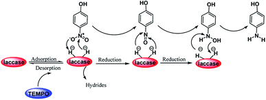 | ||
| Scheme 2 A plausible mechanism for the reduction of p-nitrophenol catalyzed by the UiO-66-NH2/TTACP/Ni@Pd NPs catalyst. | ||
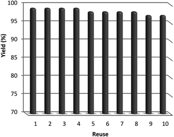
After the reaction, the heterogeneous property of the TEMPO@FeNi3/DFNS–laccase MNPs improved the impressive recovery of the reaction mixture. The activity of recycled catalyst was analyzed to 10 times causing notable loss in catalytic activity. After the response, the catalyst was separated using the process of filtration, shown in Fig. 11. Then, it was washed by methanol and put to dry using a pump.
Conclusions
The successful synthesis of TEMPO@FeNi3/DFNS–laccase MNPs is achieved in this study. The effect of varying aqueous conditions in the reduction of aromatic nitro compounds using synthesized TEMPO@FeNi3/DFNS–laccase MNPs were studied as well. It was found that TEMPO@FeNi3/DFNS–laccase MNPs performed sufficient in reduction of aromatic nitro compounds in aqueous environment. The increment of synthesized TEMPO@FeNi3/DFNS–laccase MNPs dosage has minimal effect in the reduction of aromatic nitro compounds. In addition to that, TEMPO@FeNi3/DFNS–laccase MNPs showed recyclability as the negligible decrement in efficiency were observed after each cycle testing. This signifies its potential to be recovered and used repeatedly. Based on the results shown, TEMPO@FeNi3/DFNS–laccase MNPs exhibited high efficiency for reduction of aromatic nitro compounds. In addition to its easy synthesis method, recyclability and convenient recovery, it is concluded that TEMPO@FeNi3/DFNS–laccase MNPs can be used in the removal and degradation of persistent, pharmaceutical organic pollutants.Conflicts of interest
There are no conflicts to declare.Notes and references
- Y. Jang, S. Kim, S. W. Jun, B. H. Kim, S. Hwang, I. K. Song, B. M. Kim and T. Hyeon, Chem. Commun., 2011, 47, 3601–3603 RSC.
- F. A. Khan, J. Dash, C. Sudheer and R. K. Gupta, Tetrahedron Lett., 2003, 44, 7783–7787 CrossRef CAS.
- G. Rai, J. M. Jeong, Y. S. Lee, H. W. Kim, D. S. Lee, J. K. Chung and M. C. Leea, Tetrahedron Lett., 2005, 46, 3987–3990 CrossRef CAS.
- Y. Shen, Y. Su and Y. Ma, RSC Adv., 2015, 5, 7597–7603 RSC.
- F. Figueras and B. Coq, J. Mol. Catal. A: Chem., 2001, 173, 223–230 CrossRef CAS.
- C. Lagrost, L. Preda, E. Volanschi and P. Hapiot, J. Electroanal. Chem., 2005, 585, 1–7 CrossRef CAS.
- R. M. Magdalene, E. G. Leelamani and G. N. M. Nanje, J. Mol. Catal. A: Chem., 2004, 223, 17–20 CrossRef CAS.
- F. Cardenas-Lizana, S. Gomez-Quero and M. A. Keane, Catal. Commun., 2008, 9, 475–481 CrossRef CAS.
- Z. Duan, G. Ma and W. Zhang, Bull. Korean Chem. Soc., 2012, 33, 4003–4006 CrossRef CAS.
- N. Yan, Y. Yuan and P. J. Dyson, Dalton Trans., 2013, 42, 13294–13304 RSC.
- A. Dhakshinamoorthy, M. Alvaro and H. Garcia, ACS Catal., 2011, 1, 48–53 CrossRef CAS.
- D. M. Mate and M. Alcalde, Microb. Biotechnol., 2017, 10, 1457–1467 CrossRef CAS PubMed.
- C. Chao, Y. F. Zhao, H. J. Guan, G. X. Liu, Z. G. Hu and B. Zhang, Environ. Eng. Sci., 2017, 34, 762–770 CrossRef CAS.
- J. Su, J. J. Fu, Q. Wang, C. Silva and A. Cavaco-Paulo, Crit. Rev. Biotechnol., 2018, 38, 294–307 CrossRef CAS PubMed.
- D. M. Mate and M. Alcalde, Biotechnol. Adv., 2015, 33, 25–40 CrossRef CAS PubMed.
- J. R. Jeon and Y. S. Chang, Trends Biotechnol., 2013, 31, 335–341 CrossRef CAS PubMed.
- T. Kudanga and M. Le Roes-Hill, Appl. Microbiol. Biotechnol., 2014, 98, 6525–6542 CrossRef CAS PubMed.
- A. Das and S. S. Stahl, Angew. Chem., 2017, 56, 8892–8897 CrossRef CAS PubMed.
- K. Engström, E. V. Johnston, O. Verho, K. P. J. Gustafson, M. Shakeri, C. W. Tai and J. E. Bäckvall, Angew. Chem., 2013, 125, 14256–14260 CrossRef.
- H. Shekari, M. Sayadi, M. Rezaei and A. Allahresani, Surf. Interfaces, 2017, 8, 199–205 CrossRef CAS.
- A. Maity and V. Polshettiwar, ChemSusChem, 2017, 10, 3866–3913 CrossRef CAS PubMed.
- S. M. Sadeghzadeh, Microporous Mesoporous Mater., 2016, 234, 310–316 CrossRef CAS.
- U. Patil, A. Fihri, A. H. Emwas and V. Polshettiwar, Chem. Sci., 2012, 3, 2224–2229 RSC.
- V. Polshettiwar, J. ThivolleCazat, M. Taoufik, F. Stoffelbach, S. Norsic and J. M. Basset, Angew. Chem., Int. Ed., 2011, 50, 2747–2751 CrossRef CAS PubMed.
- A. Fihri, D. Cha, M. Bouhrara, N. Almana and V. Polshettiwar, ChemSusChem, 2012, 5, 85–89 CrossRef CAS PubMed.
- A. Fihri, M. Bouhrara, U. Patil, D. Cha, Y. Saih and V. Polshettiwar, ACS Catal., 2012, 2, 1425–1431 CrossRef CAS.
- S. M. Sadeghzadeh, ChemPlusChem, 2014, 79, 278–283 CrossRef CAS PubMed.
- L. Fan, J. Wang, X. Zhang, S. M. Sadeghzadeh, R. Zhiani, M. Shahroudi and F. Amarloo, Catal. Lett., 2019, 149, 3465–3475 CrossRef CAS.
| This journal is © The Royal Society of Chemistry 2020 |

