 Open Access Article
SiO2@MnOx@Na2WO4@SiO2 core–shell-derived catalyst for oxidative coupling of methane†
La-Hee Parkab,
Ye Rim Jo a,
Jae-Wook Choia,
Dong Jin Suhab,
Kwang Ho Song
 bc and
Jeong-Myeong Ha
 *abd
*abd
aClean Energy Research Center, Korea Institute of Science and Technology, Seoul 02792, Republic of Korea. E-mail: jmha@kist.re.kr
bGraduate School of Energy and Environment (Green School), Korea University, Seoul 02841, Republic of Korea
cDepartment of Chemical and Biological Engineering, Korea University, Seoul 02841, Republic of Korea
dDivision of Energy and Environment Technology, KIST School, Korea University of Science and Technology, Seoul 02792, Republic of Korea
First published on 13th October 2020
Abstract
SiO2@MnOx@Na2WO4@SiO2 core–shell catalysts were prepared and their fabrication was confirmed using transmission electron microscopy. The formation of Mn-based nanosheets on the silica spheres is important for the deposition of nanoscopic Na2WO4. The SiO2@MnOx@Na2WO4@SiO2 core–shell catalysts were used for the oxidative coupling of methane at a temperature of 700–800 °C at which the nanostructures were completely destroyed. Although the core–shell structures did not survive the high-temperature oxidative coupling of methane, the selective production of olefins and paraffins can be attributed to highly dispersed Na2WO4 derived from confined core–shell structures.
1. Introduction
Methane is a major component of natural gas and potential feedstock for the production of chemicals and fuels.1,2 While it is a building block for the preparation of many complex organic chemicals, the conversion of stable C–H bonds is difficult. Methane can be indirectly transformed into larger organic molecules via synthesis gas.3 It can also be directly converted into functionalized building blocks including methanol,4 methyl halides,5 and ethylene.6 Oxidative coupling of methane (OCM) to paraffins and olefins has attracted much interest because of its high productivity.3,7,8 Because catalysts are important for the determination of the efficiency of OCM, many catalysts have been suggested for the development of economically feasible processes.7,9,10Several metal oxide catalysts including perovskites,11,12 metal oxide nanoparticles,13 and other mixed metal oxides14 have been proposed for the active and selective OCM process. One of the most efficient OCM catalysts,15 Na2WO4/Mn/SiO2 can be fabricated by depositing Na2WO4 and Mn on an SiO2 support. Although the reaction mechanism is still controversial,9 it has been suggested that Na2WO4 and Mn act as active component and promoter, respectively.9,16,17 Scientists attempted to improve the Na2WO4/Mn/SiO2 catalyst by adding promoters16,18,19 and modifying the support,20 but nanostructured Na2WO4/Mn/SiO2 has not been used because of the high OCM reaction temperature.
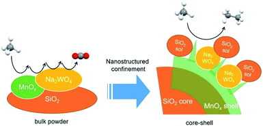
In this study, core–shell structures composed of Na2WO4–Mn–SiO2 were prepared as precursors of OCM catalysts (Scheme 1). Based on the active or selective catalysis using core–shell structures reported in the literature,21,22 the objectives of building a core–shell structure are the (i) dispersion of Na2WO4 and Mn on the silica surface, (ii) stabilization of Na2WO4 and Mn components at the high reaction temperatures of 700–900 °C, and (iii) formation of possible Na2WO4, Mn, and SiO2 complexes to achieve an improved catalytic activity. Particularly, an outer shell of SiO2 was added to immobilize Na2WO4 and MnOx shells at the high reaction temperature and to potentially prepare a highly dispersed mixture of Na2WO4, MnOx, and silica which could improve the catalytic activity. By using the highly dispersed Na2WO4 of the core–shell precursors, the selective formation of ethane and ethylene is favored compared with the bulk Na2WO4/Mn/SiO2 catalyst, which allows the deep oxidation to CO2. While well-defined core–shell structures cannot survive at high OCM reaction temperatures, they control the final annealed structures and thus potentially the OCM activity and selectivity. Active OCM components that are nano-confined by the initial core–shell structures can be prepared. The step-by-step preparation of core–shell particles and improvement of the OCM activity are discussed in this paper.
2. Methods
2.1. Materials
All chemicals were used without further purification. Sodium tungstate dihydrate (Na2WO4·2H2O) was purchased from Yakuri Pure Chemicals (Kyoto, Japan). Potassium permanganate (KMnO4, 99.3%) was purchased from Daejung Co., Ltd. (Siheung, Korea). Manganese acetate tetrahydrate [Mn(CH3CO)2·4H2O, 99.99%] was purchased from Sigma-Aldrich (St. Louis, Missouri, USA). Silica gel (SiO2, 70–230 mesh, 99.5%) was purchased from Alfa Aesar (Haverhill, Massachusetts, USA). The TEOS [Si(OC2H5)4] was purchased from Sigma-Aldrich (St. Louis, Missouri, USA). Aqueous ammonia solution (NH3 (aq), 28.0–30.0%) was purchased from Sigma-Aldrich (St. Louis, Missouri, USA). Methane (99.5%), oxygen (99.95%), and nitrogen (99.9%) were purchased from Shinyang Sanso (Seoul, Korea). Deionized (DI) water (18.2 MΩ m) was prepared using an aquaMAX-Ultra 370 series water purification system (Young Lin Instruments, Anyang, Korea).2.2. Preparation of supported powder catalysts
The mixed slurry method was used to prepare Na2WO4/Mn/SiO2 catalysts with 5 wt% Na2WO4 and 2 wt% Mn supported by SiO2.23 A silica gel support (28 g) was mixed with DI water (150 mL) and stirred at 105 °C for 1 h. The Mn(NO3)2·6H2O (1.8 mL) dissolved in DI water (10 mL) and Na2WO4·2H2O (1.684 g) dissolved in DI water (10 mL) were drop-wise added to the boiling mixture for 15 min using a syringe pump. The generated thick paste was dried in air at 105 °C for 16 h and then calcined in air at 800 °C for 5 h. Prior to the reaction, the catalyst powder was sieved using a 150–250 mesh. Using the same procedure, additional catalysts were prepared by adding KMnO4 or Mn(CH3CO)2·4H2O.2.3. Preparation of SiO2 spheres
The silica spheres used as cores were prepared using the Stöber method.24–26 For this purpose, TEOS (30 mL) was hydrolysed in ethanol (170 mL) in the presence of aqueous ammonia solution (190 mL) and DI water (10 mL). The solvent was uniformly mixed using an impeller and added using a separatory funnel to hydrolyse the TEOS at a constant rate. The obtained silica spheres were washed with DI water and ethanol, centrifuged in a suspension, and dried in an oven at 80 °C for 24 h.2.4. Preparation of SiO2@MnOx
The Mn species were deposited on the silica spheres (SiO2@MnOx) using a hydrothermal method. To prepare SiO2@MnxOy, the silica spheres (0.3 g) were dispersed in DI water (20 mL) at 30 °C for 1 h using ultrasonication,27 followed by the addition of KMnO4 (0.015–1.8 g) or Mn(CH3CO)2·4H2O (or Mn-acetate, 0.15–1.8 g). Subsequently, the suspension was transferred to a Teflon-lined stainless-steel autoclave-type reactor and heated to 150 °C at a heating rate of 10 °C min−1; the temperature was maintained at 150 °C for 48 h.28–30 The autoclave-type reactor was then cooled to room temperature under ambient conditions. Subsequently, the SiO2@MnOx(KMnO4) and SiO2@MnOx(Mn-acetate) core–shell structures were collected by centrifugation and washed five times or more with ethanol and DI water. Potassium ions were removed by washing the core–shell structures.2.5. Preparation of SiO2@MnOx@Na2WO4
The Na2WO4 was deposited on SiO2@MnOx by drying an aqueous Na2WO4 solution in an oil bath. The Na2WO4·2H2O (0.012 g) dissolved in DI water (15 mL) was stirred for 30 min at room temperature. The SiO2@MnOx (0.2 g) was added to the mixture, which then was stirred for an hour. The suspension was transferred to an oil bath preheated to 105 °C and stirred until the water solvent was completely evaporated. The prepared powder was dried in air at 80 °C for 6 h to completely remove any moisture.2.6. Preparation of SiO2@MnOx@Na2WO4@SiO2 core–shell structures
Nanostructured core–shell catalysts with three shell layers composed of the active components of the OCM catalyst were synthesized. First, the TEOS was hydrolysed using the Stöber method to fabricate silica spheres with sizes between 600–800 nm, which were used as cores. Subsequently, two manganese precursors were selected, and the silica spheres were coated with the MnOx shells using hydrothermal synthesis in a Teflon-lined stainless-steel autoclave. To attach Na2WO4 to the surface of the prepared SiO2@MnOx, DI water, Na2WO4·2H2O, and SiO2@MnOx were added, followed by heating and stirring. Finally, the same method was used to fabricate silica spheres for the silica coating on the outermost layer of the catalyst.2.7. Characterization of nanomaterials
Scanning electron microscopy (SEM) images of the catalysts were obtained using a Nova Nano SEM 200 instrument (FEI, Hillsboro, Oregon, USA). High-angle annular dark-field scanning transmission electron microscopy (HAADF-STEM) images of the catalysts were obtained using a Talos F200X instrument (FEI, Hillsboro, Oregon, USA). Both analyses were performed at the Korea Institute of Science and Technology (KIST) Advanced Analysis Center (Seoul, Korea). XRD results were collected using a Shimadzu XRD-6000 device equipped with a CuKα1 (λ = 0.15406 nm) source.2.8. Catalytic activity measurement
The catalytic reaction was performed in a fixed bed reactor. The outlets and inlets of the quartz reactor had the same size (internal diameter = 6 mm, external diameter = 8 mm). The catalyst bed was in the center of the reactor and the quartz wool was placed in the upper and lower layers of the catalyst bed. To minimize any homogeneous reactions, ZrSiO4 beads (Cenotec, Co., Ltd.) were added to the quartz reactor. The CH4 and O2 reactants diluted with N2, flowed to the catalyst bed with each gas flow was controlled by a mass flow controller (MFC). The catalyst bed was primed with a N2 flow for 30 min prior to the reaction. Water produced during the OCM reaction was removed using a cold trap connected to a −2 °C chiller (Jeio Tech, VTRC-620) and the CH4, O2, N2, CO, CO2, and hydrocarbons were analysed using the methanizer-equipped-flame ionization detector (FID), thermal conductivity detector (TCD) and FID of online gas chromatograph (GC, Agilent 7890A with ShinCarbon ST GC Columns (micropacked, RESTEK, 100/120 mesh, 2 m, 80 psi) was used to detect hydrocarbons. The catalysis results were calculated as follows:The standard deviations of measured CH4 conversion and C2+ selectivity were less than 5 and 3%, respectively.
3. Results and discussion
3.1. Preparation of SiO2@MnOx particles
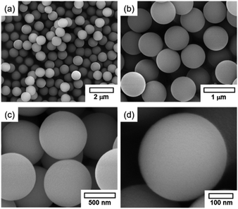
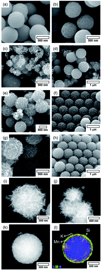
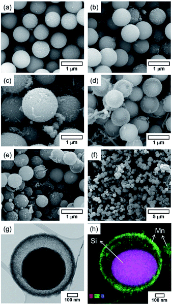
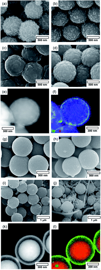
Prior to the fabrication of core–shell particles, silica spheres with diameters of 600–800 nm (Fig. 1) were prepared using the Stöber method.24–26 The SiO2@MnOx (Mn oxide shell deposited on SiO2 spheres) was prepared by the deposition of MnOx on the cores of the silica spheres. The MnOx was deposited with a hydrothermal method utilizing KMnO4 and Mn(CH3CO)2·H2O (Mn-acetate) as Mn species precursors.28,29 The morphologies of the Mn shells differ depending on the Mn precursors. When KMnO4 was used, plate-like shells formed on the surfaces of silica spheres. The morphology depends on the concentration of KMnO4; the (KMnO4)/(SiO2) ratio ranged from 0.02 to 2.22 (mol/mol). At a (KMnO4)/(SiO2) ratio of 0.02–0.76 (mol/mol), SiO2, the spheres were not completely covered with Mn species. However, they were completely covered at a (KMnO4)/(SiO2) ratio of 1.52 (mol/mol) or higher. The Mn species, which completely cover the SiO2 spheres, form nanoplate-like structures with a complex morphology that are stacked on top of each other (Fig. 2(f–h)). The transmission electron microscopy (TEM) images and energy dispersive X-ray spectroscopy (EDS) maps of SiO2@MnOx(KMnO4) confirm the deposition of nanoplate-like Mn species on the SiO2 spheres and formation of Mn shells on SiO2 spheres (Fig. 2(i–l)), respectively.In addition to KMnO4, Mn-acetate was added to the silica spheres. The Mn-acetate forms shells on the silica spheres and Mn oxide nanowires (not deposited on the silica surface; Fig. 3(a–f)). Interestingly, the EDS maps indicate the formation of yolk–shell-like structures, creating empty space between the MnOx shells and silica spheres (Fig. 3(g and h)).
3.2. Preparation of SiO2@MnOx@Na2WO4
The Na2WO4 was added to SiO2@MnOx(KMnO4) and SiO2@MnOx(Mn-acetate). The deposition of Na2WO4 was analysed using EDS maps (Fig. 4). The morphology of SiO2@MnOx@Na2WO4 insignificantly differs from that of SiO2@MnOx. These observations indicate the Na2WO4 deposition in the empty space between the MnOx nanosheets and stabilization of Na2WO4 by MnOx shells. The roughness of the MnOx shells improves the deposition of Na2WO4 (Fig. 2 and 3). Note that Na2WO4 could not be deposited on the silica spheres without Mn species when a mixture of aqueous Na2WO4 solution and silica spheres was used, which indicates that it is difficult to deposit Na2WO4 on the silica surface and that an interaction between Na2WO4 and MnOx is required for the formation of a Na2WO4 layer.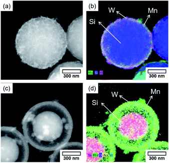 | ||
| Fig. 4 HAADF-STEM images and EDS maps of (a and b) SiO2@MnOx(KMnO4)@Na2WO4 and (c and d) SiO2@MnOx(Mn-acetate)@Na2WO4. | ||
3.3. Preparation of SiO2@MnOx@Na2WO4@SiO2
The SiO2@MnOx@Na2WO4@SiO2 core–shell catalyst was prepared by forming a silica shell on SiO2@MnOx@Na2WO4 (Fig. 5 and S1†). The thickness of the top SiO2 shell was controlled by changing the quantity of tetraethyl orthosilicate (TEOS) precursors that were added to SiO2@MnOx@Na2WO4. Regarding the SiO2@MnOx(KMnO4)@Na2WO4@SiO2 catalyst, the top shell of SiO2 forms a rough surface, mimicking the surface morphology (Na2WO4 layer) of SiO2@MnOx(KMnO4)@Na2WO4. With increasing concentration of top-shell SiO2, small SiO2 particles (∼100 nm) form, covering the surface of SiO2@MnOx(KMnO4)@Na2WO4. The EDS maps and TEM images indicate the formation of thin SiO2 layers on the surface. Top-shell SiO2 also forms on the surface of the SiO2@MnOx(Mn-acetate)@Na2WO4@SiO2 catalyst. During the Mn-acetate deposition, isolated Mn rods form, which are also coated with SiO2. The EDS maps and TEM images indicate that the deposition of SiO2 insignificantly changes the core–shell structure of SiO2@MnOx(Mn-acetate)@Na2WO4.3.4. OCM using core–shell structures
Core–shell catalysts prepared were used for the OCM (Fig. 6 and Table S1†). The OCM activity of SiO2@MnOx(KMnO4)@Na2WO4@SiO2 was measured and compared with those of SiO2@MnOx(KMnO4)@Na2WO4 without outer SiO2 shell, SiO2@MnOx(Mn-acetate)@Na2WO4@SiO2, and conventional Na2WO4/Mn/SiO2. Although SiO2@MnOx(KMnO4)@Na2WO4@SiO2 was covered by the outer SiO2 shell, it exhibited the slightly higher C2+ selectivity compared to Na2WO4/Mn/SiO2 at 740–800 °C. SiO2@MnOx(Mn-acetate)@Na2WO4@SiO2 exhibited poor OCM activity with lower CH4 conversion and the lower C2+ selectivity which was confirmed by the EDS-STEM images (Fig. 7). SiO2@MnOx(KMnO4)@Na2WO4 without the outer SiO2 shell also exhibited lower CH4 conversion (4.3–17.0%) compared to SiO2@MnOx(KMnO4)@Na2WO4@SiO2 (10.8–25.4%). The higher OCM activity of SiO2@MnOx(KMnO4)@Na2WO4@SiO2 compared to that of SiO2@MnOx(KMnO4)@Na2WO4 without the outer SiO2 shell can be attributed to the better dispersed Na2WO4 and MnOx mixed with the outer SiO2 shell as depicted in the EDS-STEM images (Fig. 7). With increasing gas hourly space velocity (GHSV) or decreasing contact time, CH4 conversion decreased, and the C2+ selectivity slightly increased (Table S2†). The long term stability of SiO2@MnOx(KMnO4)@Na2WO4@SiO2 was also observed, as a stable C2+ yield was observed for up to 100 h. That said, the C2+ selectivity decreased slightly up to 20 h and remained stable thereafter (Fig. S2†).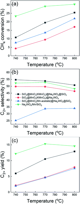 | ||
Fig. 6 Results of oxidative coupling of methane using core–shell catalysts. GHSV = 20![[thin space (1/6-em)]](https://www.rsc.org/images/entities/char_2009.gif) 000 h−1, CH4/O2/N2 = 3/1/1 mol/mol/mol. 000 h−1, CH4/O2/N2 = 3/1/1 mol/mol/mol. | ||
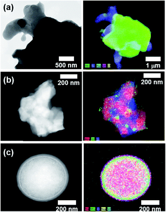 | ||
| Fig. 7 HAADF-STEM images and EDS maps of (a) Na2WO4/Mn/SiO2, (b) SiO2@MnOx(KMnO4)@Na2WO4@SiO2, and (c) SiO2@MnOx(Mn-acetate)@Na2WO4@SiO2 after the OCM reaction. | ||
The TEM results confirm that core–shell SiO2@MnOx@Na2WO4@SiO2 catalysts were successfully fabricated (Fig. 1–5). While the use of Mn as an oxygen supplier for the OCM reaction has been suggested,16 Mn is also required for the production of well-dispersed Na2WO4 on Mn-based nanosheets in the core–shell structures. The formation of Mn-based nanosheets on the silica core spheres could be clearly observed when the KMnO4 precursor was used. The better catalytic activity of SiO2@MnOx(KMnO4)@Na2WO4@SiO2 can be attributed to the deposition of well-dispersed of Na2WO4 on Mn-based nanosheets. At high OCM reaction temperatures, the core–shell structure of SiO2@MnOx(KMnO4)@Na2WO4@SiO2 collapses into a complex SiO2, MnOx, and Na2WO4 composite. The successful OCM activity of collapsed SiO2@MnOx(KMnO4)@Na2WO4@SiO2 can be attributed to the formation of well-dispersed Na2WO4 particles on the Mn-bearing SiO2 surface, which was derived from the initial core–shell structure. Core–shell structures and highly disperse catalysts are more selective with respect to the formation of C2+ compounds because of the confined Na2WO4 structure. Interestingly, SiO2@MnOx(Mn-acetate)@Na2WO4@SiO2 exhibited spherical core–shell structures at high reaction temperature, despite being fully covered by the outer SiO2 shell which suppressed the OCM reaction.
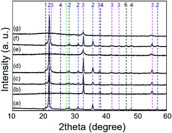
The XRD measurements indicate that the formation of α-cristobalite SiO2 was observed for SiO2@MnOx(KMnO4)@Na2WO4@SiO2 and Na2WO4/Mn/SiO2 but not for SiO2@MnOx(Mn-acetate)@Na2WO4@SiO2 (Fig. 8). Because of the stabilizing effects of α-cristobalite SiO2,17 the poor OCM activity of SiO2@MnOx(Mn-acetate)@Na2WO4@SiO2 can be attributed to the absence of α-cristobalite SiO2. The formation of α-cristobalite SiO2 for SiO2@MnOx(KMnO4)@Na2WO4@SiO2 indicated the formation of a complex mixture of Na2WO4 and the outer SiO2 shell because the permeation of Na into SiO2 nucleated the α-cristobalite SiO2.
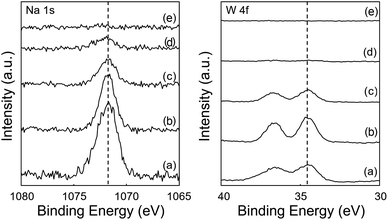
The XPS exhibited distinct peaks of tungsten (W 4f) and sodium (Na 1s) for SiO2@MnOx(KMnO4)@Na2WO4@SiO2, but not for SiO2@MnOx(Mn-acetate)@Na2WO4@SiO2 (Fig. 9). Because the OCM-active tungsten oxide was not clearly observed on the surface of SiO2@MnOx(Mn-acetate)@Na2WO4@SiO2,9,16,31,32 the OCM activity of SiO2@MnOx(Mn-acetate)@Na2WO4@SiO2 was lower than those of other catalysts. These observations can be attributed to the outer SiO2 shell blocking the active tungsten oxide for SiO2@MnOx(Mn-acetate)@Na2WO4@SiO2 as depicted in the EDS-STEM images. SiO2@MnOx(KMnO4)@Na2WO4@SiO2 exhibited appreciable W 4f peaks indicating exposed active sites for the OCM.
3.5. Reaction mechanism on the core–shell catalysts
SiO2@MnOx(KMnO4)@Na2WO4@SiO2 exhibited slightly higher C2+ selectivity compared to the conventional Na2WO4/Mn/SiO2 catalyst although it was covered by the outer SiO2 shell. The selective OCM activity can be attributed to the formation of a complex of Na2WO4, MnOx, and SiO2 as observed on the TEM, XRD, and Raman results. The presence of complex mixed oxides improved the dispersion of Na2WO4 in the mixture of MnOx and SiO2 selectively catalysing OCM.4. Conclusion
In this study, SiO2@MnOx@Na2WO4@SiO2 core–shell structures were prepared. Nanostructured shells of Mn oxide and Na2WO4 consecutively formed and were protected using SiO2 sols. Although the complex core–shell structures were destroyed at a temperature of 700–800 °C at which the OCM to olefins and paraffins was performed, highly dispersed Na2WO4 on the MnOx layer is derived from nanoscopic core–shell structures. The Na2WO4 may be confined to the complex structures of MnOx and SiO2. The catalyst derived from the core–shell Na2WO4–Mn–SiO2 complex exhibits an improved production of C2+ compounds and the further oxidation of C2+ compounds to CO and CO2 may be suppressed by highly dispersed Na2WO4.Conflicts of interest
There are no conflicts to declare.Acknowledgements
This work was supported by the C1 Gas Refinery Program of the National Research Foundation of Korea (NRF) funded by the Ministry of Science and ICT (2015M3D3A1A01064900).Notes and references
- R. T. Yunarti, S. Gu, J.-W. Choi, J. Jae, D. J. Suh and J.-M. Ha, ACS Sustainable Chem. Eng., 2017, 5, 3667–3674 CrossRef CAS.
- C. Hammond, S. Conrad and I. Hermans, ChemSusChem, 2012, 5, 1668–1686 CrossRef CAS.
- H. R. Godini, S. Xiao, S. Jašo, S. Stünkel, D. Salerno, N. X. Son, S. Song and G. Wozny, Fuel Process. Technol., 2013, 106, 684–694 CrossRef CAS.
- Z. Zakaria and S. K. Kamarudin, Renewable Sustainable Energy Rev., 2016, 65, 250–261 CrossRef CAS.
- V. Paunović and J. Pérez-Ramírez, Catal. Sci. Technol., 2019, 9, 4515–4530 RSC.
- Y. Gambo, A. A. Jalil, S. Triwahyono and A. A. Abdulrasheed, J. Ind. Eng. Chem., 2018, 59, 218–229 CrossRef CAS.
- T. Ito and J. H. Lunsford, Nature, 1985, 314, 721–722 CrossRef CAS.
- G. E. Keller and M. M. Bhasin, J. Catal., 1982, 73, 9–19 CrossRef CAS.
- S. Arndt, T. Otremba, U. Simon, M. Yildiz, H. Schubert and R. Schomäcker, Appl. Catal., A, 2012, 425–426, 53–61 CrossRef CAS.
- T. W. Elkins, B. Neumann, M. Bäumer and H. E. Hagelin-Weaver, ACS Catal., 2014, 4, 1972–1990 CrossRef CAS.
- G. Lee, I. Kim, I. Yang, J.-M. Ha, H. B. Na and J. C. Jung, Appl. Surf. Sci., 2018, 429, 55–61 CrossRef CAS.
- S. Lim, J.-W. Choi, D. J. Suh, K. H. Song, H. C. Ham and J.-M. Ha, J. Catal., 2019, 375, 478–492 CrossRef CAS.
- T. W. Elkins and H. E. Hagelin-Weaver, Appl. Catal., A, 2013, 454, 100–114 CrossRef CAS.
- J. W. Xu, Y. Zhang, Y. M. Liu, X. Z. Fang, X. L. Xu, W. M. Liu, R. Y. Zheng and X. Wang, Eur. J. Inorg. Chem., 2019, 183–194 CrossRef.
- X. Fang, S. Li, J. Lin and Y. Chu, J. Mol. Catal., 1992, 6, 427–433 CAS.
- S. Gu, H.-S. Oh, J.-W. Choi, D. J. Suh, J. Jae, J. Choi and J.-M. Ha, Appl. Catal., A, 2018, 562, 114–119 CrossRef CAS.
- Z. C. Jiang, C. J. Yu, X. P. Fang, S. B. Li and H. L. Wang, J. Phys. Chem., 1993, 97, 12870–12875 CrossRef CAS.
- N. S. Hayek, G. J. Khlief, F. Horani and O. M. Gazit, J. Catal., 2019, 376, 25–31 CrossRef CAS.
- N. Hiyoshi and T. Ikeda, Fuel Process. Technol., 2015, 133, 29–34 CrossRef CAS.
- M. Yildiz, Y. Aksu, U. Simon, T. Otremba, K. Kailasam, C. Gobel, F. Girgsdies, O. Gorke, F. Rosowski, A. Thomas, R. Schomacker and S. Arndt, Appl. Catal., A, 2016, 525, 168–179 CrossRef CAS.
- D. Sun, S. Wageh, A. A. Al-Ghamdi, Y. Le, J. Yu and C. Jiang, Appl. Surf. Sci., 2019, 466, 301–308 CrossRef CAS.
- Y.-F. Huang, X.-Y. Sun, S.-H. Huo, Y. Li and C. Zhong, Appl. Surf. Sci., 2019, 466, 637–646 CrossRef CAS.
- J. Y. Lee, W. Jeon, J.-W. Choi, Y.-W. Suh, J.-M. Ha, D. J. Suh and Y.-K. Park, Fuel, 2013, 106, 851–857 CrossRef CAS.
- W. Stöber, A. Fink and E. Bohn, J. Colloid Interface Sci., 1968, 26, 62–69 CrossRef.
- W. Li and D. Zhao, Adv. Mater., 2013, 25, 142–149 CrossRef CAS.
- X. Jiang, Y. Wang and M. Li, Sci. Rep., 2014, 4, 6070 CrossRef CAS.
- H. Shi, D. Shi, L. Yin, Z. Yang, S. Luan, J. Gao, J. Zha, J. Yin and R. K. Li, Nanoscale, 2014, 6, 13748–13753 RSC.
- D. Yuan, T. Zhang, Q. Guo, F. Qiu, D. Yang and Z. Ou, Chem. Eng. J., 2017, 327, 539–547 CrossRef CAS.
- D. Kong, M. Yu, C. Lin, X. Liu, J. Lin and J. Fang, J. Electrochem. Soc., 2005, 152, H146–H151 CrossRef CAS.
- M. Qiao, X. Lei, Y. Ma, L. Tian, W. Wang, K. Su and Q. Zhang, J. Alloys Compd., 2017, 693, 432–439 CrossRef CAS.
- Y. Kou, B. Zhang, J.-z. Niu, S.-b. Li, H.-l. Wang, T. Tanaka and S. Yoshida, J. Catal., 1998, 173, 399–408 CrossRef CAS.
- S.-B. Li, Chin. J. Chem., 2001, 19, 16–21 CrossRef CAS.
Footnote |
| † Electronic supplementary information (ESI) available. See DOI: 10.1039/d0ra05081d |
| This journal is © The Royal Society of Chemistry 2020 |

