 Open Access Article
Tailored design of p-phenylenediamine functionalized graphene decorated with cobalt ferrite for microwave absorption
Tao Ma†
 a,
Yu Cui†b,
Li Liu*a,
Hao Luana,
Jianwen Gea,
Pengfei Juc,
Fandi Menga and
Fuhui Wanga
aShenyang National Laboratory for Materials Science, Northeastern University, Shenyang 110819, China. E-mail: liuli@mail.neu.edu.cn
bInstitute of Metal Research, Chinese Academy of Sciences, Shenyang 110016, China
cShanghai Aerospace Equipment Manufacture, Shanghai 200245, China
First published on 27th August 2020
Abstract
Structural design and componential optimization are two primary directions in the study of microwave absorbers. In this study, a novel cobalt ferrite (CoFe2O4) decorated with p-phenylenediamine (PPD) functionalized graphene (PG/CoFe2O4) binary hybrid with unique hierarchical porous structure was synthesized by a two-step route. The chemical composition, morphology and electromagnetic parameters of the as-prepared sample were investigated successively. The porous CoFe2O4 microspheres with an average diameter of about 160 nm were uniformly anchored on rGO nanosheets. Owing to the uniquely hierarchical porous structure, synergistic effects of dielectric loss (conductive loss, interface and dipole polarization) and magnetic loss (eddy current loss, natural and exchange resonance), the as-prepared sample exhibited excellent microwave absorption (MA) performance. The maximum reflection loss (RLmax) could attain up to −53.3 dB, and the effective absorption bandwidth (EAB) reached 6.6 GHz (11.4–18.0 GHz) at 2.40 mm, which completely covered the Ku band. These results showed that this functional material can be applied in the MA field.
1. Introduction
In order to address the problems of microwave radiation and interference arising from the widespread use of electronic devices and equipment, it is urgent to design high-performance MA materials with the traits of light weight, thin thickness, strong absorption and wide bandwidth.1–3Graphene has drawn considerable attention in the MA field owing to its low density, large specific surface area and strong dielectric loss.4,5 However, pure graphene usually leads to bad impedance matching and weak absorption due to its high conductivity.6,7 Fortunately, the large specific surface endow it with the ability to load various particles. Hence, scholars have been dedicated to combining graphene with magnetic particles to integrate the advantages of dielectric and magnetic materials over last few years.8–10 To further achieve moderate impedance matching and attenuation capacity, different reductants and dopants were employed to fabricate graphene-based absorbers. For instance, FeNi/N-GN (hydrazine hydrate as reductant and dopant),11 Co0.8Fe2.2O4/rGO (sodium borohydride as reductant),12 FeCo/N-doped carbon/rGO (ascorbic acid),13 graphene/Fe3O4@PPy (ethylenediamine)14 and rGO/MWCNTs/ZnFe2O4 (glucose).15 In addition, it is reported that GO reduced and functionalized by PPD can form cross-linked graphene networks to greatly enhance the conductivity and increase the layer spacing to prevent restacking and aggregation.16,17 Furthermore, functional groups containing nitrogen introduced into graphene can produce defect and dipole polarization, which will conduce to MA.18–20 So it may have potential to act as a new-style dielectric material used in MA field by loading with magnetic component.
Compared to other spinel ferrites, cobalt ferrite shows high magnetic loss due to its higher saturation magnetization and magnetic anisotropy.21–23 Thus it has been widely studied as competitive candidates for absorber. For example, CoFe2O4@1T/2H-MoS2,24 CoFe2O4-Ti3C2,23 CoFe2O4/CNFs,25 C@CoFe2O4,26 and CF@CoFe2O4@MnO2.27 From above research, it is not hard to notice that CoFe2O4 was decorated with various dielectric materials to prepare high-performance absorbers. Besides, rational structure design is another way to prepare high-efficiency absorber. Among all structures, porous structure exhibits the superiority of light-weight and enhanced microwave attenuation.11 Hence, combining graphene with porous CoFe2O4 could be a reasonable design for MA.
Herein, we successfully synthesized hierarchical porous PG/CoFe2O4 binary hybrid by using PPD to functionalize and reduce GO. The PG/CoFe2O4 exhibited excellent MA performance than pure CoFe2O4. The optimal RL could reach up to −53.3 dB. The EAB attained 6.6 GHz (from 11.4 to 18.0 GHz) at 2.40 mm, covering the whole Ku band. Thus, the binary composite has great potential to be applied as newly high-performance absorber.
2. Experimental
2.1 Materials
Graphite oxide (GO) was supplied by Shenzhen Matterene Tech Co., Ltd (Shenzhen, China). Ferric chloride hexahydrate (FeCl3·6H2O), cobalt chloride hexahydrate (CoCl2·6H2O), urea, ethylene glycol, diglycol, polyvinylpyrrolidone (PVP, K30), ammonium hydroxide and ethanol were obtained from Sinopharm Chemical Reagent, China. And p-phenylenediamine was bought from Aladdin Bio-Chem Technology Co., Ltd, Shanghai, China. Deionized water was used throughout the experiments.2.2 Synthesis of PG/CoFe2O4 composite
Firstly, the CoFe2O4 was fabricated by a solvothermal method according to our previous report with some modification.28 In a typical procedure, FeCl3·6H2O (5 mmol), CoCl2·6H2O (2.5 mmol) and polyvinylpyrrolidone (K30, 0.2 g) were dissolved into 40 mL mixed solution containing same-volumetric ethylene glycol and diglycol with magnetic stirring for 40 min, then urea (40 mmol) was added. The mixture solution was sealed into Teflon-lined autoclave (50 mL) and maintained in 180 °C for 20 h. The CoFe2O4 was obtained. Secondly, the above as-prepared CoFe2O4 (500 mg) were dispersed in 100 mL 2 mg mL−1 GO aqueous solution with ultrasonically treating for 60 min. Afterwards, p-phenylenediamine (2.0 g) and ammonium hydroxide (0.6 mL) was added with further stirring for 5 h at 95 °C in oil bath pot. Finally, the PG/CoFe2O4 composite was obtained by filtrated, washed and dried. The pure PG was synthesized under the same conditions except for the addition of CoFe2O4.2.3 Characterization
The structure, morphology and electromagnetic parameters of the samples were measured by X-ray diffraction (XRD, Rigaku, Cu-Kα), Fourier transform infrared spectroscopy (FT-IR, BRUKER, VERTEX70), Raman spectra (HORIBA, XPLORA), X-ray photoelectron spectrometer (XPS, Thermo VG, ESCALAB250), scanning electron microscopy (SEM, JEOL, JSM-7001F), transmission electron microscopy (TEM, JEOL, JEM-2100F), energy dispersive X-ray spectroscopy (EDS) and vector network analyzer (Agilent E5071C), respectively. The specimens of electromagnetic parameters were tested by mixing samples with paraffin by the mass ratio of 1![[thin space (1/6-em)]](https://www.rsc.org/images/entities/char_2009.gif) :
:![[thin space (1/6-em)]](https://www.rsc.org/images/entities/char_2009.gif) 1, and then pressed into toroidal shape of φout = 7.00 mm and φin = 3.04 mm with a thickness of 2.0 mm.
1, and then pressed into toroidal shape of φout = 7.00 mm and φin = 3.04 mm with a thickness of 2.0 mm.
3. Results and discussion
The synthetic route of PG/CoFe2O4 composite is schematically represented in Fig. 1a. Firstly, porous CoFe2O4 were prepared by solvothermal process with the help of surfactant PVP. Then, the CoFe2O4 microspheres were loaded on the surface of GO nanosheets under electrostatic interaction. Finally, the amine of PPD was reacted with epoxy group and carboxyl group of GO through nucleophilic substitution and condensation reaction.17,29 The GO was reduced and functionalized and PG/CoFe2O4 binary hybrid was prepared.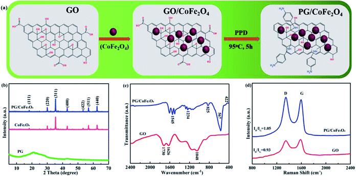 | ||
| Fig. 1 (a) Synthetic route of PG/CoFe2O4 composite, (b) XRD patterns of PG, CoFe2O4 and PG/CoFe2O4 composite, (c) FT-IR spectra and (d) Raman spectra of GO and PG/CoFe2O4 composite. | ||
The XRD patterns of PG, CoFe2O4 and PG/CoFe2O4 composite are shown in Fig. 1b. The PG exhibits a broad characteristic peak at around 20.8° instead of 11° (graphene oxide), indicating that GO was reduced to PG with the presence of p-phenylenediamine. For CoFe2O4, the diffraction peaks are obtained at 18.3°, 30.1°, 35.4°, 43.1°, 53.5°, 57.0° and 62.6°, which assign to the (111), (220), (311), (400), (422), (511) and (440) planes of CoFe2O4 (JCPDS card no. 22-1086).24 The peaks of PG/CoFe2O4 composite are nearly the same with CoFe2O4. In addition, the characteristic peak of PG is disappeared, which is on account of PG layers were separated by interbedded CoFe2O4 to avoid stacking.30
Fig. 1c shows FT-IR spectra of GO and PG/CoFe2O4 composite. The GO exhibits four distinct characteristic peaks at 1730 cm−1 (C![[double bond, length as m-dash]](https://www.rsc.org/images/entities/char_e001.gif) O in carboxyl group), 1626 cm−1 (C
O in carboxyl group), 1626 cm−1 (C![[double bond, length as m-dash]](https://www.rsc.org/images/entities/char_e001.gif) C in aromatic ring) and 1048 cm−1 (C–O in epoxide group).31 For PG/CoFe2O4 composite, the peaks corresponding to epoxide and carboxyl group weaken or vanish. Meanwhile, three new peaks are detected at 1545 cm−1, 1234 cm−1 and 825 cm−1 assigning to the stretching vibration of N–H in –C–NH2 groups, stretching vibration of C–N in C–NH–C bonds and asymmetric 1,4-substituent of benzene ring.32 All the results imply that the epoxide and carboxyl groups of GO were reacted with the amine group of PPD to form PG effectively. In addition, another two new peaks at 567 cm−1 and 422 cm−1 associated with vibrations of Fe–O and Co–O bonds further indicate the presence of CoFe2O4.
C in aromatic ring) and 1048 cm−1 (C–O in epoxide group).31 For PG/CoFe2O4 composite, the peaks corresponding to epoxide and carboxyl group weaken or vanish. Meanwhile, three new peaks are detected at 1545 cm−1, 1234 cm−1 and 825 cm−1 assigning to the stretching vibration of N–H in –C–NH2 groups, stretching vibration of C–N in C–NH–C bonds and asymmetric 1,4-substituent of benzene ring.32 All the results imply that the epoxide and carboxyl groups of GO were reacted with the amine group of PPD to form PG effectively. In addition, another two new peaks at 567 cm−1 and 422 cm−1 associated with vibrations of Fe–O and Co–O bonds further indicate the presence of CoFe2O4.
Fig. 1d presents Raman spectra of GO and PG/CoFe2O4 composite. It can be observed that both samples present two distinct peaks called D band (1349 cm−1) and G band (1591 cm−1), relating to the vibration of sp3 defects and the disorder sites and in-plane sp2 hybridization. Moreover, the intensity of ID/IG is usually used to characterize the defects and disorders of carbon materials. The ID/IG of PG/CoFe2O4 is 1.05, which is higher than that of GO (0.93). It suggests that the introduction of PPD can destroy the ordered sp2 domains and generate more defects and disorders in PG/CoFe2O4 composite, further it will contribute to microwave absorption.33
The element composition and formation of chemical bond of GO and PG was analyzed by XPS. The survey spectra of GO and PG are shown in Fig. 2a. The GO presents two peaks of C 1s and O 1s. After functionalized by PPD, there exists a new peak of N 1s for PG. Meanwhile, the oxygen amount was reduced from 31.72% (GO) to 7.90% (PG). The high-resolution C 1s spectra of GO and PG are exhibited in Fig. 2b and c, respectively. For GO, it can be fitted into four peaks at 284.4, 286.3, 287.0 and 288.3 eV, assigning to the groups of C–C/C![[double bond, length as m-dash]](https://www.rsc.org/images/entities/char_e001.gif) C (aromatic rings), C–OH (hydroxyl), C–O–C (epoxy) and C–O
C (aromatic rings), C–OH (hydroxyl), C–O–C (epoxy) and C–O![[double bond, length as m-dash]](https://www.rsc.org/images/entities/char_e001.gif) C (carboxyl), respectively. As for PG, the peaks corresponding to epoxide and carboxyl groups disappear and a new peak appears at 285.6 eV ascribed to C–N group. The results further confirm that the epoxide and carboxyl groups of GO were reacted with the amine group of PPD.
C (carboxyl), respectively. As for PG, the peaks corresponding to epoxide and carboxyl groups disappear and a new peak appears at 285.6 eV ascribed to C–N group. The results further confirm that the epoxide and carboxyl groups of GO were reacted with the amine group of PPD.
The morphology and microstructure of CoFe2O4 and PG/CoFe2O4 composite are investigated by SEM and TEM, as shown in Fig. 3. In Fig. 3a–c, the CoFe2O4 presents a spherical shape and the average diameter of about 160 nm. Moreover, it exhibits an uneven surface and a mass of nano-holes are well distributed in CoFe2O4 microparticle. This porous structure not only decreases the density but also optimizes impedance matching. Besides, it can induce plentiful interfaces and to generate interfacial polarization and multiple reflection.34 For PG/CoFe2O4 (Fig. 3d and e), the wrinkled and transparent sheets are supposed to PG (marked in blue arrow) and porous CoFe2O4 particles (marked in red arrow) are uniformly embedded in the surface of PG to prevent restacking. In Fig. 3f, the HRTEM image shows the lattice spacing of 0.29 nm, assigning to the (220) plane of CoFe2O4. And this result is in consistent with XRD and FT-IR characterizations. The elemental mapping analysis (Fig. 3g) shows that PG/CoFe2O4 composite consists of Co, Fe, O, C and N elements. It indicates that CoFe2O4 was wrapped by PG. Importantly, it further suggests that PG was doped with N element, which can induce more defect and dipole relaxation.19
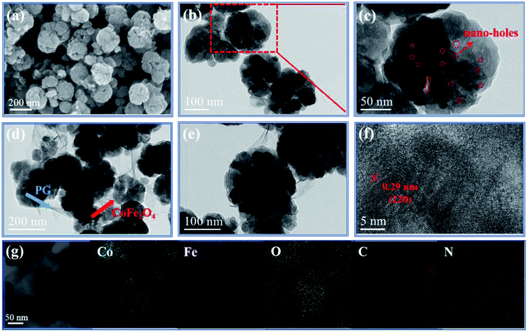 | ||
| Fig. 3 SEM image of (a) CoFe2O4, TEM images of (b and c) CoFe2O4 and (d and e) PG/CoFe2O4 composite, (f) HRTEM image and (g) elemental mapping distribution of PG/CoFe2O4 composite. | ||
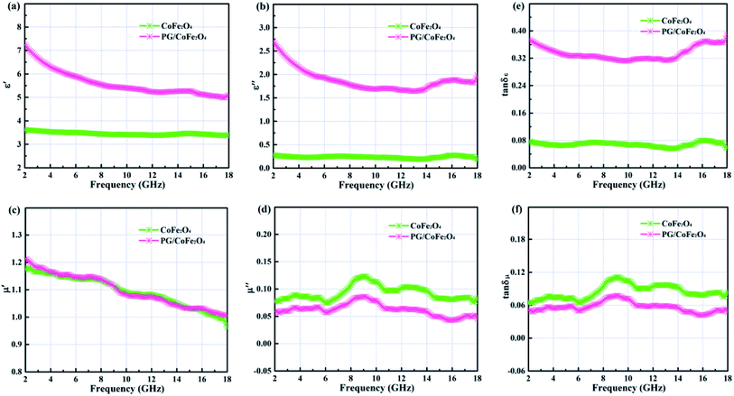
Fig. 4a–d illustrates the complex permittivity (εr = ε′ − jε′′) and complex permeability (μr = μ′ − jμ′′) of CoFe2O4 and PG/CoFe2O4 composite. In general, the real parts (ε′ and μ′) represents the storage of electromagnetic energy, and the imaginary parts (ε′′ and μ′′) symbolizes the dissipation of electromagnetic energy.35 As shown in Fig. 4a and b, the ε′ and ε′′ values of CoFe2O4 exhibit slight variation with the change of frequency, ranging from 3.6–3.3 and 0.34–0.16, respectively. As for PG/CoFe2O4 composite, it shows a declining trend with the increasing frequency, ranging from 7.3–4.9 and 2.72–1.55, respectively. Obviously, compared to CoFe2O4, the ε′ and ε′′ values of PG/CoFe2O4 increase significantly in the whole frequency. In Fig. 4c and d, the μ′ values decrease with the changing frequency and the μ′′ values present some fluctuations for both CoFe2O4 and PG/CoFe2O4. And owing to the adding of nonmagnetic PG, the μ′′ value of PG/CoFe2O4 is lower than that of CoFe2O4 in the entire frequency. Further, the corresponding dielectric loss tangent (tan![[thin space (1/6-em)]](https://www.rsc.org/images/entities/char_2009.gif) δε = ε′′/ε′) and magnetic loss tangent (tan
δε = ε′′/ε′) and magnetic loss tangent (tan![[thin space (1/6-em)]](https://www.rsc.org/images/entities/char_2009.gif) δμ = μ′′/μ′) are shown in Fig. 4e and f. It suggests that tan
δμ = μ′′/μ′) are shown in Fig. 4e and f. It suggests that tan![[thin space (1/6-em)]](https://www.rsc.org/images/entities/char_2009.gif) δε value increases greatly and tan
δε value increases greatly and tan![[thin space (1/6-em)]](https://www.rsc.org/images/entities/char_2009.gif) δμ value decreases slightly with the introduction of PG. And the value of tan
δμ value decreases slightly with the introduction of PG. And the value of tan![[thin space (1/6-em)]](https://www.rsc.org/images/entities/char_2009.gif) δε is much larger that tan
δε is much larger that tan![[thin space (1/6-em)]](https://www.rsc.org/images/entities/char_2009.gif) δμ in the whole frequency for PG/CoFe2O4, confirming that the dielectric loss plays a dominant role in MA for PG/CoFe2O4 composite.
δμ in the whole frequency for PG/CoFe2O4, confirming that the dielectric loss plays a dominant role in MA for PG/CoFe2O4 composite.
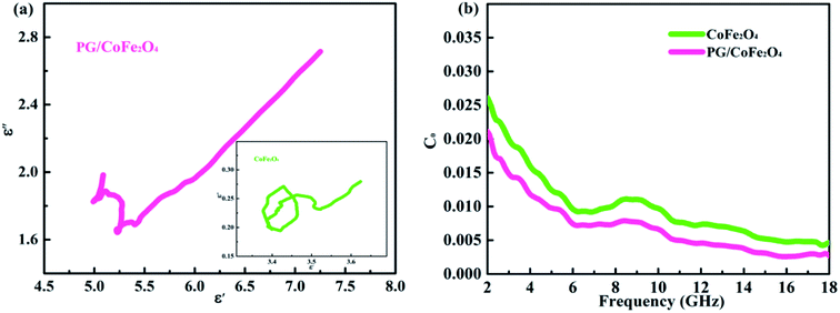
The dielectric loss of an absorber generally associates with conductive loss and polarization relaxation.36 In terms of conductive loss, based on free electron theory (σ = ε0ε′′2πf), the higher conductivity (σ) leads to larger dielectric imaginary parts (ε′′), and further increases dielectric loss.37 Herein, the introduction of PG greatly enhances the conductivity of PG/CoFe2O4 composite, hence its dielectric loss is significantly improved compared to CoFe2O4. With regard to polarization relaxation, interfacial polarization and dipole polarization are usually considered in microwave frequency range.38 According to Debye relaxation theory, the plot of ε′–ε′′ is a single semicircle (Cole–Cole semicircle) and each semicircle stands for a Debye relaxation process.39 As shown in Fig. 5a, both samples present more than one imperfect semicircle, indicating multiple Debye relaxation processes. The multiple interfaces between CoFe2O4 and PG, cavities of CoFe2O4 microsphere will induce abundant interfacial polarization. Moreover, the structural defects, nitrogen-doping and residual group of PG can act as polarization center to generate dipole polarization.19,20 In addition, the long line tail of plot for PG/CoFe2O4 further confirms the conductive loss due to introduction of PG.40
The magnetic loss is composed of hysteresis loss, domain-wall resonance, exchange resonance, eddy current loss and natural resonance.24 In microwave band, it mainly attributed to eddy current loss, natural and exchange resonance.22,36 The eddy current loss can be expressed as C0 = μ′′(μ′)−2f−1 = 2πμ0σd2/3.41,42 If magnetic loss only derive from eddy current effect, the C0 will be a constant in the whole frequency. As shown in Fig. 5b, the values of C0 are changeable for both samples, especially in 2–6 GHz. This result suggests that magnetic loss is caused by eddy current loss, natural resonance (2–6 GHz) and exchange resonance (exceed 6 GHz) jointly.
The reflection loss can be assessed by transmission line theory and is given as follows:43
RL (dB) = 20![[thin space (1/6-em)]](https://www.rsc.org/images/entities/char_2009.gif) log|(Zin − Z0)/(Zin + Z0)| log|(Zin − Z0)/(Zin + Z0)|
| (1) |
Zin = Z0(μr/εr)1/2![[thin space (1/6-em)]](https://www.rsc.org/images/entities/char_2009.gif) tanh[j(2πfd/c)(μr × εr)1/2] tanh[j(2πfd/c)(μr × εr)1/2]
| (2) |
Fig. 6a–c depicts the frequency-dependent RL curves of CoFe2O4 and PG/CoFe2O4 with different thickness. For CoFe2O4 shown in Fig. 6a, the RLmax is −22.5 dB at 18.0 GHz with EAB (RL less than −10 dB) of 3.8 GHz (14.2–18.0 GHz) for the thickness of 2.32 mm. It indicates that pure CoFe2O4 exhibits poor MA performance. For PG/CoFe2O4 shown in Fig. 6b and c, the RLmax value of −53.3 dB at 2.61 mm and the corresponding EAB of 6.0 GHz (10.3–16.3 GHz). Moreover, when thickness of 2.40 mm, the ultra-broad bandwidth attains 6.6 GHz (11.4–18.0 GHz), covering the whole Ku band. And the EAB is 4.7 GHz (8.0–12.7 GHz) at 3.20 mm, which can completely cover the X band. Additionally, the comparative MA performance of some graphene-based absorbers is summarized in Table 1. Obviously, the PG/CoFe2O4 composite exhibits preferable MA performance with both strong absorption and wide bandwidth.
 | ||
| Fig. 6 Frequency dependence of RL with different thickness for (a) CoFe2O4 and (b and c) PG/CoFe2O4 composite. | ||
| Absorber | RLmax (dB) | EAB (GHz) | Thickness (mm) | Ref. |
|---|---|---|---|---|
| Fe-doped SnO2/rGO | −29.0 | 2.7 | 5.30 | 44 |
| Graphene/SiC | −37.1 | 2.2 | 2.60 | 45 |
| Ti3C2Tx@rGO | −31.2 | 5.4 | 2.05 | 46 |
| BiFeO3/rGO | −46.7 | 4.7 | 1.80 | 47 |
| N/B12-rGO | −52.0 | 6.0 | 2.80 | 48 |
| PANI/GA | −42.3 | 3.2 | 3.00 | 49 |
| γ-Fe2O3/PNG | −40.18 | 3.41 | 2.50 | 50 |
| PG/CoFe2O4 | −53.3 | 6.0 | 2.61 | This work |
| PG/CoFe2O4 | −29.3 | 6.6 | 2.40 | This work |
Noticeably, the frequency associated with RLmax exhibits a lower trend with the increasing thickness. This phenomenon can be explained by quarter-wavelength (λ/4) cancellation model with following equation:51
 | (3) |
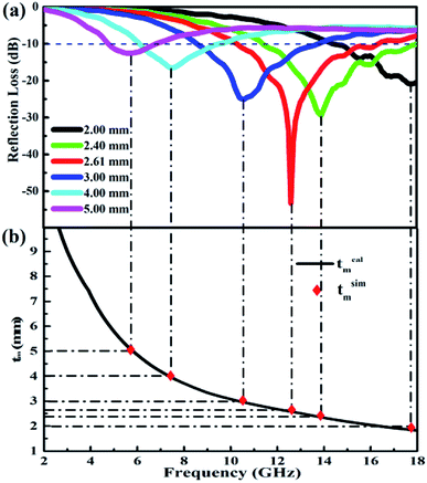 | ||
| Fig. 7 Frequency dependence of (a) RL with different thickness, and (b) the tm–fm curve of PG/CoFe2O4 composite. | ||
An excellent absorber should simultaneously fulfill two requirements, including strong attenuation capacity and favorable impedance matching. Generally, the attenuation constant (α) is used to assess attenuation capacity of absorber and it can be expressed as follows:52
 | (4) |
As shown in Fig. 8a, the α value of PG/CoFe2O4 is larger than CoFe2O4 in the whole frequency, suggesting the strong attenuation ability of PG/CoFe2O4. Meanwhile, normalized characteristic impedance (Z = |Zin/Z0|) is applied to evaluate the transmission behaviors of microwave. The Z = 1 means all incident microwaves enter into absorber without reflection.53 As presented in Fig. 8b, the Z value is closer to 1 in most of frequency range for PG/CoFe2O4 at 2.61 mm, which is much better than that of CoFe2O4. Therefore, the impedance matching of composite is improved by introducing PG. The PG/CoFe2O4 composite possesses higher attenuation capacity and superb impedance matching, leading to excellent MA performance.
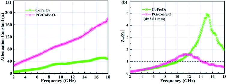 | ||
| Fig. 8 Frequency dependence of (a) attenuation constant α and (b) normalized characteristic impedance Z at 2.61 mm of PG/CoFe2O4 composite. | ||
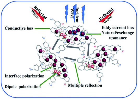
The MA mechanism of PG/CoFe2O4 composite is elaborated in Fig. 9. The superb MA performance can be ascribed to uniquely hierarchical porous structure, synergistic effects of dielectric loss (conductive loss, interface and dipole polarization) and magnetic loss (eddy current loss, natural and exchange resonance). Firstly, the PG nanosheets establish a conductive network to generate conductive loss. Secondly, the structural defects, nitrogen-doping and residual group of PG can produce dipole polarization. Thirdly, abundant interfaces between CoFe2O4 and PG create interface polarization, adjacent layers of PG and cavities of CoFe2O4 can generate multiple reflection. Fourthly, the CoFe2O4 microspheres induce eddy current loss, natural and exchange resonance. Lastly, the appropriate dielectric and magnetic loss facilitate good impedance matching. Therefore, the PG/CoFe2O4 composite exhibits excellent MA performance.
4. Conclusions
In summary, the hierarchical PG/CoFe2O4 binary hybrid was prepared by using PPD to functionalize and reduce GO. Owing to the introduction of PG, the PG/CoFe2O4 composite present superb MA performance than pure CoFe2O4. The strong RLmax of −53.3 dB and the ultra-broad bandwidth attains 6.6 GHz from 11.4 to 18.0 GHz at 2.40 mm, which completely covered the Ku band. When thickness of 3.20 mm, the EAB was 4.7 GHz (8.0–12.7 GHz), which covered the whole X band. This functional binary composite has great potential to be used in MA field and even in other fields.Conflicts of interest
There are no conflicts to declare.Acknowledgements
The investigation was supported by the National Natural Science Foundation of China under the contract No. 51871049, the Fundamental Research Funds for the Central Universities under the contract No. 2017YFB0702303, Liao Ning Revitalization Talents Program under the contract No. XLYC1807076 and International Cooperation Fund of Shanghai Science and Technology Commission under the contract No. 17520731800.References
- L. Wang, Y. Huang, X. Sun, H. Huang, P. Liu, M. Zong and Y. Wang, Nanoscale, 2014, 6, 3157–3164 RSC
.
- Z. Zhao, S. Xu, Z. Du, C. Jiang and X. Huang, ACS Sustainable Chem. Eng., 2019, 7, 7183–7192 CrossRef CAS
.
- X. Zhang, X. Zhang, H. Yuan, K. Li, Q. Ouyang, C. Zhu, S. Zhang and Y. Chen, Chem. Eng. J., 2020, 383, 123208 CrossRef
.
- M. Zhang, Z. Jiang, H. Si, X. Zhang, C. Liu, C. Gong, Y. Zhang and J. Zhang, Phys. Chem. Chem. Phys., 2020, 22, 8639–8646 RSC
.
- S. Zhao, C. Wang and B. Zhong, J. Magn. Magn. Mater., 2020, 495, 165753 CrossRef CAS
.
- G. Wen, X. Zhao, Y. Liu, H. Zhang and C. Wang, Chem. Eng. J., 2019, 372, 1–11 CrossRef CAS
.
- N. Zhang, Y. Huang and M. Wang, J. Colloid Interface Sci., 2018, 530, 212–222 CrossRef CAS PubMed
.
- J. Li, D. Zhou, W.-F. Liu, J.-Z. Su and M.-S. Fu, Scr. Mater., 2019, 171, 42–46 CrossRef CAS
.
- W. Xu, G.-S. Wang and P.-G. Yin, Carbon, 2018, 139, 759–767 CrossRef CAS
.
- H.-B. Zhao, J.-B. Cheng, J.-Y. Zhu and Y.-Z. Wang, J. Mater. Chem. C, 2019, 7, 441–448 RSC
.
- J. Feng, Y. Zong, Y. Sun, Y. Zhang, X. Yang, G. Long, Y. Wang, X. Li and X. Zheng, Chem. Eng. J., 2018, 345, 441–451 CrossRef CAS
.
- W. Shen, B. Ren, K. Cai, Y.-F. Song and W. Wang, J. Alloys Compd., 2019, 774, 997–1008 CrossRef CAS
.
- S. Wang, Y. Xu, R. Fu, H. Zhu, Q. Jiao, T. Feng, C. Feng, D. Shi, H. Li and Y. Zhao, Nano-Micro Lett., 2019, 11, 76 CrossRef
.
- J. Li, H. Ji, Y. Xu, J. Zhang and Y. Yan, J. Mater. Res. Technol., 2020, 9, 762–772 CrossRef CAS
.
- R. Shu, G. Zhang, J. Zhang, X. Wang, M. Wang, Y. Gan, J. Shi and J. He, J. Alloys Compd., 2018, 736, 1–11 CrossRef CAS
.
- H.-L. Ma, H.-B. Zhang, Q.-H. Hu, W.-J. Li, Z.-G. Jiang, Z.-Z. Yu and A. Dasari, ACS Appl. Mater. Interfaces, 2012, 4, 1948–1953 CrossRef CAS PubMed
.
- B. Song, J. Choi, Y. Zhu, Z. Geng, L. Zhang, Z. Lin, C. Tuan, K. Moon and C. Wong, Chem. Mater., 2016, 28, 9110–9121 CrossRef CAS
.
- H. Yuan, F. Yan, C. Li, C. Zhu, X. Zhang and Y. Chen, ACS Appl. Mater. Interfaces, 2018, 10, 1399–1407 CrossRef CAS PubMed
.
- Y. Wang, X. Gao, X. Wu, W. Zhang, C. Luo and P. Liu, Chem. Eng. J., 2019, 375, 121942 CrossRef CAS
.
- R. Shu, J. Zhang, C. Guo, Y. Wu, Z. Wan, J. Shi, Y. Liu and M. Zheng, Chem. Eng. J., 2020, 384, 123266 CrossRef CAS
.
- Y. Ren, S. Li, B. Dai and X. Huang, Appl. Surf. Sci., 2014, 311, 1–4 CrossRef CAS
.
- T. Zhu, S. Chang, Y.-F. Song, M. Lahoubi and W. Wang, Chem. Eng. J., 2019, 373, 755–766 CrossRef CAS
.
- J. He, S. Liu, L. Deng, D. Shan, C. Cao, H. Luo and S. Yan, Appl. Surf. Sci., 2020, 504, 144210 CrossRef CAS
.
- X. Wang, T. Zhu, S. Chang, Y. Lu, W. Mi and W. Wang, ACS Appl. Mater. Interfaces, 2020, 12, 11252–11264 CrossRef PubMed
.
- Y. Li, M. Yuan, H. Liu and G. Sun, J. Alloys Compd., 2020, 826, 154147 CrossRef CAS
.
- L. Huang, J. Li, Z. Wang, Y. Li, X. He and Y. Yuan, Carbon, 2019, 143, 507–516 CrossRef CAS
.
- A. Feng, T. Hou, Z. Jia and G. Wu, RSC Adv., 2020, 10, 10510–10518 RSC
.
- T. Ma, Y. Cui, Y. Sha, L. Liu, J. Ge, F. Meng and F. Wang, Synth. Met., 2020, 265, 116407 CrossRef CAS
.
- A. A. Ibrahim, A. Lin, M. S. Adly and M. S. El-Shall, J. Catal., 2020, 385, 194–203 CrossRef CAS
.
- X.-J. Zhang, G.-S. Wang, W.-Q. Cao, Y.-Z. Wei, J.-F. Liang, L. Guo and M.-S. Cao, ACS Appl. Mater. Interfaces, 2014, 6, 7471–7478 CrossRef CAS PubMed
.
- Y. Lei, Z. Yao, H. Lin, A. A. Haidry, J. Zhou and P. Liu, Mater. Lett., 2019, 236, 456–459 CrossRef CAS
.
- A. Wang, L. Cheng, X. Chen, W. Zhao, C. Li, W. Zhu and D. Shang, Dyes Pigm., 2019, 160, 344–352 CrossRef CAS
.
- F. Yan, Y. Zong, C. Zhao, G. Tan, Y. Sun, X. Li, Z. Ren and X. Zheng, J. Alloys Compd., 2018, 742, 928–936 CrossRef CAS
.
- Z. Xiang, J. Xiong, B. Deng, E. Cui, L. Yu, Q. Zeng, K. Pei, R. Che and W. Lu, J. Mater. Chem. C, 2020, 8, 2123–2134 RSC
.
- L. Liang, Z. Zhang, F. Song, W. Zhang, H. Li, J. Gu, Q. Liu and D. Zhang, Carbon, 2020, 162, 283–291 CrossRef CAS
.
- H. Zhao, Y. Cheng, Y. Zhang, Z. Zhang, L. Zhou and B. Zhang, Dalton Trans., 2019, 48, 15263–15271 RSC
.
- B. Mordina, R. Kumar, R. K. Tiwari, D. K. Setua and A. Sharma, J. Phys. Chem. C, 2017, 121, 7810–7820 CrossRef
.
- M. Zeng, Q. Cao, J. Liu, B. Guo, X. Hao, Q. Liu, X. Liu, X. Sun, X. Zhang and R. Yu, ACS Appl. Mater. Interfaces, 2020, 12, 1222–1231 CrossRef CAS PubMed
.
- S. Wang, S. Peng, S. Zhong and W. Jiang, J. Mater. Chem. C, 2018, 6, 9465–9474 RSC
.
- H. Wang, F. Meng, F. Huang, C. Jing, Y. Li, W. Wei and Z. Zhou, ACS Appl. Mater. Interfaces, 2019, 11, 12142–12153 CrossRef CAS PubMed
.
- X. Zhang, J. Xu, X. Liu, S. Zhang, H. Yuan, C. Zhu, X. Zhang and Y. Chen, Carbon, 2019, 155, 233–242 CrossRef CAS
.
- J. Liu, H. Liang and H. Wu, Composites, Part A, 2020, 130, 105760 CrossRef CAS
.
- Y. Cheng, Y. Zhao, H. Zhao, H. Lv, X. Qi, J. Cao, G. Ji and Y. Du, Chem. Eng. J., 2019, 372, 390–398 CrossRef CAS
.
- J. Zhang, R. Shu, Y. Ma, X. Tang and G. Zhang, J. Alloys Compd., 2019, 777, 1115–1123 CrossRef CAS
.
- X. Li, Z. Li, L. Que, Y. Ma, L. Zhu and C. Pei, J. Alloys Compd., 2020, 835, 155172 CrossRef CAS
.
- L. Wang, H. Liu, X. Lv, G. Cui and G. Gu, J. Alloys Compd., 2020, 828, 154251 CrossRef CAS
.
- X. Gao, Y. Wang, Q. Wang, X. Wu, W. Zhang, M. Zong and L. Zhang, Ceram. Int., 2019, 45, 3325–3332 CrossRef CAS
.
- Z. Sun, Z. Yan, K. Yue, A. Li and L. Qian, Composites, Part B, 2020, 196, 108132 CrossRef CAS
.
- Y. Wang, X. Gao, Y. Fu, X. Wu, Q. Wang, W. Zhang and C. Luo, Composites, Part B, 2019, 169, 221–228 CrossRef CAS
.
- S. Wang, Q. Jiao, Q. Shi, H. Zhu, T. Feng, Q. Lu, C. Feng, H. Li, D. Shi and Y. Zhao, Ceram. Int., 2020, 46, 1002–1010 CrossRef CAS
.
- R. Wang, M. He, Y. Zhou, S. Nie, Y. Wang, W. Liu, Q. He, W. Wu, X. Bu and X. Yang, ACS Appl. Mater. Interfaces, 2019, 11, 38361–38371 CrossRef CAS PubMed
.
- L. Liang, G. Han, Y. Li, B. Zhao, B. Zhou, Y. Feng, J. Ma, Y. Wang, R. Zhang and C. Liu, ACS Appl. Mater. Interfaces, 2019, 11, 25399–25409 CrossRef CAS PubMed
.
- J. Xiong, Z. Xiang, B. Deng, M. Wu, L. Yu, Z. Liu, E. Cui, F. Pan, R. Liu and W. Lu, Appl. Surf. Sci., 2020, 513, 145778 CrossRef CAS
.
Footnote |
| † Contributed to this work equally. |
| This journal is © The Royal Society of Chemistry 2020 |


