 Open Access Article
The in situ preparation of iron phosphide using ionic liquids as iron and phosphorus sources for efficient hydrogen evolution reactions†
Yanping
Chen
ab,
Tianhao
Li
 *ab,
Qichao
Zhao
 c,
Dingyu
Liu
ab and
Chang Ming
Li
 ab
ab
aSchool of Materials and Energy, Southwest University, Chongqing 400715, China. E-mail: tli7@swu.edu.cn
bChongqing Key Laboratory for Advanced Materials and Technologies of Clean Energy, Chongqing 400715, China
cBureau of Hydrology, Changjiang Water Resources Commission, Wuhan 430010, China
First published on 7th September 2020
Abstract
Ionic liquids (ILs) were utilized as iron and phosphorus sources for the preparation of iron phosphide for the first time. The IL trihexyl(tetradecyl)phosphonium tetrachloroferrate ([P(C6H13)3C14H29][FeCl4]) and carbon nanotubes (CNTs) were applied as precursors for the in situ preparation of Fe2P(IL6)/CNTs. This material has good catalytic activity and stability for the hydrogen evolution reaction, including a low onset overpotential (75 mV) and Tafel slope (68 mV dec−1). Moreover, this catalyst exhibits current densities of 10 and 20 mA cm−2 at overpotentials of 115 and 150 mV, respectively. The phosphidation process using [P(C6H13)3C14H29][FeCl4] was also investigated. All experimental results indicate that Fe2P can be formed in situ on the CNTs using this IL, and that the CNTs help the formation of the Fe2P nanoparticles and improve the electrical conductivity. This IL-based in situ preparation strategy is facile and environmentally friendly and does not require the addition of other reagents. This method holds great promise for application in other electrochemical studies.
Introduction
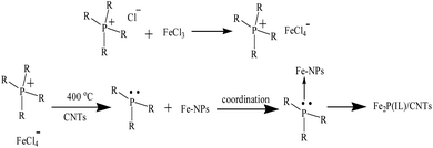
Due to the environmental impact of fossil fuels and the energy crisis, the development of some clean, low-carbon emission, renewable and efficient energy sources to replace fossil fuels is required. Hydrogen is a sustainable and green energy source and a carrier with a high energy density, which could enable the world to meet future energy demand. Water electrolysis is a simple and reliable method to generate H2 without carbon emissions and normally needs a high overpotential.1 In order to decrease the required overpotential and to increase the current density, electrocatalysts for the hydrogen evolution reaction (HER) are highly desired. Noble metal-based catalysts have excellent HER activities but their high price and low abundance have restricted their practical application.2 Also, the proton exchange membrane used for water splitting demands that the HER electrocatalyst is acid-stable.3 Thus, it is necessary to develop some inexpensive, stable and highly efficient catalysts for the HER.4 Recently, transition metal phosphides (TMPs) have been introduced as a promising catalyst material due to their low-cost, good catalytic efficiency and stability.5 Various kinds of TMPs have been prepared as electrocatalysts for the HER, such as MoP, WP, NiP, FeP and CoP.6–11 Amongst the transition metals, iron is the cheapest and most abundant, so iron phosphide-based catalysts, including FeP, Fe2P, Fe3P and FeMnP, have been introduced and widely applied in the HER.12–14 To prepare iron phosphide, different iron salts (e.g. FeCl3 and FeSO4) and phosphorus compounds (e.g. trioctylphosphine and NaH2PO2) have frequently been used as the Fe and P sources, respectively.12–17 However, some of these preparation methods have adopted complicated procedures to obtain a good HER performance.6,12–17 Hence, it is vital to develop a simple approach to the synthesis of iron phosphide with novel Fe and P sources.Ionic liquids (ILs) are organic molten salts that possess low melting points (<100 °C). Various ILs have been applied in the HER due to their high conductivities and stabilities.18–20 In our previous study, an IL with a tetrachloroferrate anion was synthesized and applied as the iron source to prepare FeP for use in the HER. The resulting FeP showed good catalytic activity.21 However, this synthetic process is tedious and time consuming, and an additional P source is needed for the preparation of FeP. Thus, it is essential to use some novel metal and phosphorus sources to simplify the preparation route. In this study, an in situ iron phosphide preparation method was developed, where ILs containing a phosphonium cation and a tetrachloroferrate anion were utilized as a dual iron and phosphorus source for the first time. Generally, trihexyl(tetradecyl)phosphonium tetrachloroferrate ([P(C6H13)3C14H29][FeCl4]) and tetrabutylphosphonium tetrachloroferrate ([P(C4H9)4][FeCl4]) were quickly synthesized, and then these two ILs were mixed with carbon nanotubes (CNTs) to prepare the Fe2P(IL6)/CNTs and Fe2P(IL4)/CNTs materials via low temperature pyrolysis (Scheme 1). These as-prepared iron phosphides exhibited good HER activity and stability. During the preparation, the CNTs facilitated the formation of the Fe2P nanoparticles as well as improving the conductivity of these catalysts. This IL-based in situ preparation strategy is uncomplicated, quick, and environmentally friendly without needing the addition of other organic solvents and harmful reagents. It holds great promise for applications in other electrochemical studies.
Experimental
Chemicals
Trihexyl(tetradecyl)phosphonium chloride ([P(C6H13)3C14H29][Cl]), tetrabutylphosphonium chloride ([P(C4H9)4][Cl]), iron(III) chloride hexahydrate (FeCl3·6H2O) and other reagents were purchased from Titansci Co. China. Multi-walled carbon nanotubes (CNTs) were supplied by Shenzhen Nanotech Port Ltd, Co. China.Synthesis of ionic liquids and the preparation of Fe2P
Two ionic liquids (ILs), namely trihexyl(tetradecyl)phosphonium tetrachloroferrate ([P(C6H13)3C14H29][FeCl4]) and tetrabutylphosphonium tetrachloroferrate ([P(C4H9)4][FeCl4]), were synthesized via a previously reported procedure.22 Generally, [P(C6H13)3C14H29][Cl] was mixed with FeCl3·6H2O in methanol for 24 h at room temperature and the dark red product was automatically separated from the solvent. After removing the solvent, the homogeneous product was dried under vacuum to afford [P(C6H13)3C14H29][FeCl4]. Then, this IL was mixed with CNTs in a mortar to obtain a IL6/CNTs mixture, which was subsequently pyrolyzed in a tube furnace for in situ preparation of Fe2P(IL6)/CNTs (400 °C in an Ar atmosphere for 2 h) (Scheme 1). Similarly, [P(C4H9)4][Cl] was reacted with FeCl3·6H2O to synthesize [P(C4H9)4][FeCl4], which was further mixed with CNTs and pyrolyzed to obtain Fe2P(IL4)/CNTs. For comparison, [P(C6H13)3C14H29][FeCl4] was directly pyrolyzed without CNTs to prepare Fe2P(IL6) under the same conditions. FeCl3·6H2O was mixed with CNTs and sodium hypophosphite (NaH2PO2) and was then pyrolyzed to prepare FeP/CNTs under the same conditions.Electrocatalytic performance
All electrochemical measurements were conducted on an electrochemical workstation (CHI-760E) with a three-electrode configuration at ambient temperature, where a glassy carbon electrode (GCE, 0.126 cm2), a carbon rod and a saturated calomel electrode (SCE) were employed as the working electrode, the counter electrode and the reference electrode in 0.5 M H2SO4, respectively. 10 μL of a catalyst ethanol solution (5 mg ml−1) with Nafion (5 wt%) was dropped on the clean GCE and dried to prepare the working electrode. For each analysis, the measurement was repeated at least three times. The linear sweep voltammograms (LSV) were performed at a scan rate of 2 mV s−1 (from 0.2 to −1 V). The electrochemical impedance spectroscopy (EIS) measurements of the catalysts were recorded at −400 mV over a frequency range of 0.1–1000 kHz with a 5 mA amplitude of current perturbation.Characterization
The morphology and structure of the material were studied using field emission scanning electron microscopy (FE-SEM, JEOL-7800F), transmission electron microscopy (TEM, JEM-2100) and energy dispersive X-ray spectroscopy (EDX, INCA X-Max 250). The measurement of the X-ray diffraction (XRD) patterns was conducted using a RigakuD/Max 2550 diffractometer with Cu Kα radiation (λ = 1.5418 Å). X-ray photoelectron spectroscopy (XPS) characterization was performed using a ESCALAB 250Xi spectrometer with Al Kα (150 W, 1486.6 eV) radiation. The specific surface area was analyzed using a nitrogen adsorption method (BET method) through a TriStar II 3020 gas sorption analyzer.Results and discussion
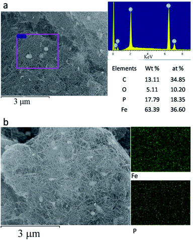
The morphology of the Fe2P(IL6)/CNTs was examined using FE-SEM and TEM. As shown in Fig. 1 and S1 in the ESI,† Fe2P was uniformly generated in situ on the CNTs. These Fe2P nanoparticles are sphere-shaped with a diameter of approximately 40–70 nm. These images clearly illustrate that the Fe2P nanospheres are wrapped in the CNTs. Moreover, a size distribution histogram based on the TEM images was obtained (Fig. S2†), showing that the diameters of the particles almost ranged from 40–60 nm. The energy dispersive spectroscopy (EDS) analysis reveals that C, O, P and Fe are the main elements of Fe2P(IL6)/CNTs. The EDS mapping results indicate that the Fe and P are evenly spread on the CNTs (Fig. 2 and S3†). It also suggests that during the preparation, the CNTs uniformly disperse the [P(C6H13)3C14H29][FeCl4] for in situ formation of the Fe2P nanospheres. Furthermore, the EDS pattern (Fig. 2a) shows that the atomic percentage of Fe and P in Fe2P(IL6)/CNTs was 36.6 and 18.35%, respectively. These results indicate that the Fe and P molar ratio in the catalyst is 2![[thin space (1/6-em)]](https://www.rsc.org/images/entities/char_2009.gif) :
:![[thin space (1/6-em)]](https://www.rsc.org/images/entities/char_2009.gif) 1, yet this ratio is 1
1, yet this ratio is 1![[thin space (1/6-em)]](https://www.rsc.org/images/entities/char_2009.gif) :
:![[thin space (1/6-em)]](https://www.rsc.org/images/entities/char_2009.gif) 1 in the [P(C6H13)3C14H29][FeCl4] IL. A possible reason for this change in the Fe
1 in the [P(C6H13)3C14H29][FeCl4] IL. A possible reason for this change in the Fe![[thin space (1/6-em)]](https://www.rsc.org/images/entities/char_2009.gif) :
:![[thin space (1/6-em)]](https://www.rsc.org/images/entities/char_2009.gif) P ratio could be that during the preparation process (Scheme 1) some of the phosphorus formed may react with other atoms (such as Cl and H) to form volatiles that are transferred out of the tube furnace by the carrier gas (Ar). Moreover, this change in stoichiometric ratio preliminarily demonstrates the formation of Fe2P. For comparison, SEM, TEM and EDS analyses were also performed for Fe2P(IL4)/CNTs, FeP/CNTs and Fe2P(IL6). As shown in Fig. 1, 2 and S4–S6,† Fe2P(IL6)/CNTs has a smaller particle size and a higher Fe2P content than Fe2P(IL4)/CNTs and FeP/CNTs. The FeP/CNTs nanoparticles were aggregated and the Fe2P(IL6) sample has a large sheet morphology.
P ratio could be that during the preparation process (Scheme 1) some of the phosphorus formed may react with other atoms (such as Cl and H) to form volatiles that are transferred out of the tube furnace by the carrier gas (Ar). Moreover, this change in stoichiometric ratio preliminarily demonstrates the formation of Fe2P. For comparison, SEM, TEM and EDS analyses were also performed for Fe2P(IL4)/CNTs, FeP/CNTs and Fe2P(IL6). As shown in Fig. 1, 2 and S4–S6,† Fe2P(IL6)/CNTs has a smaller particle size and a higher Fe2P content than Fe2P(IL4)/CNTs and FeP/CNTs. The FeP/CNTs nanoparticles were aggregated and the Fe2P(IL6) sample has a large sheet morphology.
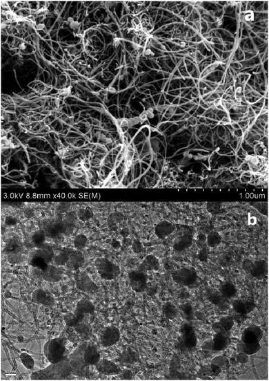 | ||
| Fig. 1 (a) An SEM image of Fe2P(IL6)/CNTs; and (b) a TEM image of Fe2P(IL6)/CNTs (scale bar: 50 nm). | ||
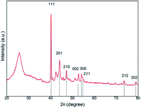
In addition, XRD and XPS characterizations of Fe2P(IL6)/CNTs were carried out to further confirm the formation of Fe2P. The broad peak in the XRD pattern from 20 to 28° can be assigned to the presence of CNTs in this material. The XRD pattern of Fe2P(IL6)/CNTs displayed characteristic diffraction peaks at 40.4° (111), 44.2° (201), 47.3° (210), 52.9° (002), 54.1° (300), 54.6° (211), 73.6° (212) and 79.1° (302), which is in agreement with the Fe2P reference pattern (PDF#51-0943) (Fig. 3).23 The small positive shift of the Fe2P(IL6)/CNTs peaks may result from the oxygen dopant observed in the EDS data.10 Some of the iron could be oxidized during the phosphidation and so the unidentified peak around 43° may be attributed to the iron oxidized species. A Scherrer analysis of the XRD data was conducted, and the results indicated that the average grain size is 52.7 nm (Fig. S2†), which is in accordance with the TEM data. Bonding information relating to Fe2P(IL6)/CNTs was investigated through XPS analysis. In the Fe 2p spectrum (Fig. 4a) two broad peaks were observed at binding energies (BEs) of 712.6 eV and 726.7 eV. These are most likely related to the amorphous iron oxide species (Fe–O) in the material, indicating that the Fe3+ was not totally reduced to a zero valence state.24 Two sharp peaks were found at 707.5 eV (Fe 2p3/2) and 720.3 eV (Fe 2p1/2). Also, the P 2p spectrum reveals two peaks located at 129.4 eV (P 2p3/2) and 130.1 eV (P 2p1/2). The Fe 2p3/2 peak (707.5 eV) is a little higher than that of elemental Fe (707.0 eV) while the P 2p3/2 peak (129.4 eV) is a little lower than that of elemental P (130.2 eV), which is consistent with the structure of Fe2P.25–27 Also, it suggests that electrons were transferred from iron to phosphorus, where Fe and P have a partial positive charge (δ+) and a partial negative charge (δ−), respectively.28,29 Another peak located at 133.9 eV may arise from the oxidized P species, suggesting the formation of phosphorous based oxides (Fig. 4b).28,29 The existence of oxidized Fe and P can be assumed to arise from the surface oxidation of Fe2P under ambient conditions.28 In addition, the relative area ratio of the P 2p peak area at 133.9 eV is higher than that of the other P 2p peaks. Its higher proportion could be the possible reason for these broad peaks and the peak shift observed in the XRD patterns.
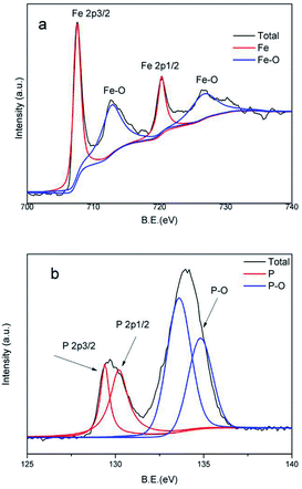 | ||
| Fig. 4 (a) The Fe 2p XPS spectrum of Fe2P(IL6)/CNTs; and (b) the P 2p XPS spectrum of Fe2P(IL6)/CNTs. | ||
In this study, [P(C6H13)3C14H29][FeCl4] was utilized as a dual P and Fe source for in situ preparation of Fe2P. Previous investigations have demonstrated that the quaternary phosphonium cation of an IL can decompose to a trialkylphosphine (TAP) and that the metal-based anion can be reduced to give metal nanoparticles (M–NPs).30,31 This TAP, utilized as an organophosphine to prepare transition metal phosphides (TMPs), can exhibit a strong coordination interaction with the M–NPs to form a complex, such as Ni–TAP or Co–TAP.32,33 In this case, Fe–TAP was generated during the pyrolysis step and the P–C bond could be broken to form phosphorus. Finally, the metal and phosphorus react to obtain the TMP.5 Accordingly, the possible synthetic route for Fe2P using [P(C6H13)3C14H29][FeCl4] is described in Scheme 1. During the preparation, the IL can also be used as a solvent and a stabilizer to prevent the aggregation of the nanoparticles.19,34 Furthermore, according to the TEM and SEM images of all four materials, Fe2P(IL6) is a large bulky material on the micrometer scale while the other three catalysts with CNTs are on the nanometer scale. Thus, the CNTs are favorable for the formation of iron phosphide nanoparticles by dispersing the IL and avoiding aggregation.
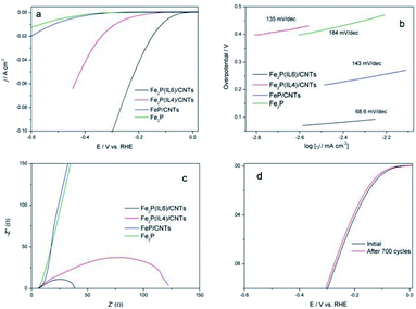
The HER activities of Fe2P(IL6)/CNTs and Fe2P(IL4)/CNTs were studied. Fe2P(IL6) and FeP/CNTs, pyrolyzed from [P(C6H13)3C14H29][FeCl4] and FeCl3·6H2O/CNTs/NaH2PO2 respectively, were introduced as control groups. As shown in Fig. 5a, Fe2P(IL6)/CNTs possesses the best HER activity, holding the lowest onset overpotential of 75 mV. It can also achieve current densities of 10 and 20 mA cm−2 at overpotentials of 115 and 150 mV, respectively. On the contrary, Fe2P(IL6) displays a much lower activity than Fe2P(IL6)/CNTs and Fe2P(IL4)/CNTs. Thus, the CNTs played a pivotal role in improving the HER performance. It is highly possible that the CNTs can disperse the IL to small droplets, which is beneficial for forming the Fe2P nanoparticles.
Tafel plots for these materials were investigated, and the corresponding Tafel slopes were calculated (Fig. 5b). The Tafel slope for Fe2P(IL6) is higher than 120 mV dec−1, suggesting that a Volmer step (proton adsorption) is the rate-limiting step.35 On the contrary, the Tafel slope of Fe2P(IL6)/CNTs is the lowest (68 mV dec−1), revealing that this process is a Volmer–Heyrovsky reaction and that the rate-limiting step is a Heyrovsky step (charge transfer step). Therefore, enhancing the conductivity and electron transfer ability of the material could significantly improve the catalytic activity of Fe2P(IL6)/CNTs. In addition, the low Tafel slope of Fe2P(IL6)/CNTs demonstrates good hydrogen evolution kinetics and a low energy barrier for H2 electrochemical desorption.
Electrochemical Impedance Spectroscopy (EIS) analysis was conducted to further evaluate catalytic performance. As shown in Fig. 5c, Fe2P(IL6)/CNTs possesses the lowest faradaic impedance (∼30 Ω) while Fe2P(IL6) has a much higher impedance. This demonstrates that Fe2P(IL6)/CNTs possesses a high electrical conductivity and good electron transfer ability which, given that charge transfer is the rate-limiting step for this catalyst, can dramatically improve the catalytic activity. Thus, it is worth noting that the CNTs can not only facilitate the fabrication of the Fe2P nanoparticles, but also improve the HER performance.
Additionally, both Fe2P(IL6)/CNTs and Fe2P(IL4)/CNTs have a better HER performance than FeP/CNTs, showing that the IL can improve HER activity (Table 1). The possible reason could be the carbonization of the IL cation during pyrolysis, which increases the electrical conductivity of the materials.16 Also, the EDS results indicate that Fe2P(IL6)/CNTs and Fe2P(IL4)/CNTs have a higher iron phosphide content than that of FeP/CNTs, improving the HER performance.
| Catalyst | Onset overpotential (mV) | Tafel slope (mV dec−1) | j (mA cm−2) | η at the corresponding j (mV) | Ref. |
|---|---|---|---|---|---|
| Fe2P(IL6)/CNTs | 75 | 68 | 10 | 115 | This work |
| 20 | 150 | ||||
| Fe2P(IL4)CNTs | 120 | 130 | 10 | 290 | |
| 20 | 340 | ||||
| FeP/CNTs | 350 | 143 | 10 | 520 | |
| 20 | 600 | ||||
| Fe2P | 350 | 184 | 10 | 570 | |
| FeP/C | 63 | 57 | 10 | 110 | 8 |
| 20 | 147 | ||||
| FeP NPs | 85 | 64 | 10 | 124 | 16 |
| FeP NPs/graphene | 65 | 67 | 10 | 123 | 37 |
| FeP NP-candle soot | 38 | 58 | 10 | 112 | 38 |
| FeP hollow microsphere | — | 58 | 10 | 114 | 39 |
| FeP and Fe2P nanowires | 50 | 39 | 10 | 96 | 25 |
| FeP nanorods | 150 | 55 | 10 | 120 | 40 |
| 3D-graphene aerogel CoP | — | 50 | 10 | 121 | 41 |
| MoP2 nanosheets | 90 | 81.5 | 10 | 150 | 9 |
| Ni2P nanoparticles | 75 | 46 | 10 | 102 | 19 |
When compared with [P(C4H9)4][FeCl4] (colloidal solid), P(C6H13)3C14H29][FeCl4] (liquid) is more convenient to mix with the CNTs, forming smaller IL droplets that subsequently generate smaller Fe2P particles. Brunauer–Emmett–Teller (BET) measurements were carried out. Fe2P(IL6)/CNTs has a higher surface area (163 m2 g−1) than that of Fe2P(IL4)/CNTs (145 m2 g−1), which can expose more active sites to enhance the HER activity.36 These BET results also suggest that Fe2P(IL6)/CNTs has a smaller particle size than Fe2P(IL4)/CNTs, resulting in better HER performance. Moreover, the EDS analysis indicates that Fe2P(IL6)/CNTs has a higher Fe2P content than Fe2P(IL4)/CNTs (Fig. 2b and S4†), which could be another reason for the better HER performance.
The stability of Fe2P(IL6)/CNTs in the HER was evaluated, and cyclic voltammetry (CV) over 700 scanning cycles was performed at the scan rate of 100 mV s−1. After scanning, no significant change in the LSV was observed, indicating that this catalyst possesses a good cycle life during the HER (Fig. 4d). Therefore, Fe2P(IL6)/CNTs can serve as an effective and stable HER electrocatalyst, and its catalytic activity is comparable to other TMP catalysts used for the HER (Table 1). Moreover, Fe2P(IL6) was prepared in situ on CNTs using the IL as a dual source of Fe and P, which is simple, fast and green and does not require the addition of other reagents.
The IL/CNTs ratio and pyrolysis temperature for Fe2P(IL6)/CNTs preparation were optimized. The IL to CNTs ratio was varied from 1![[thin space (1/6-em)]](https://www.rsc.org/images/entities/char_2009.gif) :
:![[thin space (1/6-em)]](https://www.rsc.org/images/entities/char_2009.gif) 1 to 10
1 to 10![[thin space (1/6-em)]](https://www.rsc.org/images/entities/char_2009.gif) :
:![[thin space (1/6-em)]](https://www.rsc.org/images/entities/char_2009.gif) 1, and the best ratio was 5
1, and the best ratio was 5![[thin space (1/6-em)]](https://www.rsc.org/images/entities/char_2009.gif) :
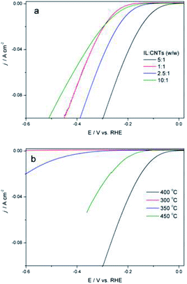
:![[thin space (1/6-em)]](https://www.rsc.org/images/entities/char_2009.gif) 1 (Fig. 6a). It is possible that a high ratio of IL to CNTs could produce more Fe2P(IL6) particles on the CNTs, while excess IL would form extra Fe2P(IL6) that deteriorates the HER performance. Next, the pyrolysis temperature was increased from 300 to 500 °C (Fig. 6b), which is, depending on the iron and phosphorus precursors, the most suitable temperature range for preparing iron phosphide.12–17 In this study, pyrolysis at too low a temperature will not obtain the final product, while too high a temperature will waste energy and increase the annealing time. Thus, 400 °C was used for phosphidation.
1 (Fig. 6a). It is possible that a high ratio of IL to CNTs could produce more Fe2P(IL6) particles on the CNTs, while excess IL would form extra Fe2P(IL6) that deteriorates the HER performance. Next, the pyrolysis temperature was increased from 300 to 500 °C (Fig. 6b), which is, depending on the iron and phosphorus precursors, the most suitable temperature range for preparing iron phosphide.12–17 In this study, pyrolysis at too low a temperature will not obtain the final product, while too high a temperature will waste energy and increase the annealing time. Thus, 400 °C was used for phosphidation.
Conclusions
Fe2P(IL6)/CNTs was successfully prepared from [P(C6H13)3C14H29][FeCl4]/CNTs, where [P(C6H13)3C14H29][FeCl4] was used as the dual source of Fe and P to fabricate Fe2P for the first time. Fe2P(IL6)/CNTs was then utilized as an electrocatalyst for the HER where it displayed good HER activity and stability. CNTs not only improve the catalytic activity but are also favorable for the preparation of the Fe2P nanoparticles. Moreover, the IL-based in situ preparation is facile and eco-friendly and does not require the addition of any other reagent. This method possesses great promise for application in other electrochemical studies. Future studies will focus on the trapping of volatiles and using gas chromatography-mass spectrometry (GC-MS) or other characterization methods to analyze the off-gases during the preparation process. This will be applied to further investigate the phosphidation mechanism.Conflicts of interest
There are no conflicts to declare.Acknowledgements
This work is financially supported by the National Natural Science Foundation of China (No. 51909012) and “Fundamental Research Funds of the Central University” (XDJK2019C004).References
- A. B. Laursen, S. Kegnæs, S. Dahl and I. Chorkendorff, Molybdenum sulfides-efficient and viable materials for electro-and photoelectrocatalytic hydrogen evolution, Energy Environ. Sci., 2012, 5, 5577 RSC.
- J. F. Callejas, C. G. Read, C. W. Roske, N. S. Lewis and R. E. Schaak, Synthesis, characterization, and properties of metal phosphide catalysts for the hydrogen-evolution reaction, Chem. Mater., 2016, 28, 6017 CrossRef CAS.
- H. Hambourger, M. Gervaldo, D. Svedruzic, P. W. King, D. Gust, M. Ghirardi, A. L. Moore and T. A. Moore, [FeFe]-Hydrogenase-catalyzed H2 production in a photoelectrochemical biofuel cell, J. Am. Chem. Soc., 2008, 130, 2015 CrossRef PubMed.
- P. F. B. D. Martins, P. P. Lopes, E. A. Ticianell, V. R. Stamenkovic, N. M. Markovic and D. Strmcnik, Hydrogen evolution reaction on copper: promoting water dissociation by tuning the surface oxophilicity, Electrochem. Commun., 2019, 100, 30 CrossRef CAS.
- Y. Shi and B. Zhang, Recent advances in transition metal phosphide nanomaterials: synthesis and applications in hydrogen evolution reaction, Chem. Soc. Rev., 2016, 45, 1529 RSC.
- F. Wang, X. Yang, B. Dong, X. Yu, H. Xue and L. Feng, A FeP powder electrocatalyst for the hydrogen evolution reaction, Electrochem. Commun., 2018, 92, 33 CrossRef CAS.
- M. Wei, L. Yang, L. Wang, T. Liu, C. Liu, Y. Tang and S. Luo, In situ potentiostatic activation to optimize electrodeposited cobalt-phosphide electrocatalyst for highly efficient hydrogen evolution in alkaline media, Chem. Phys. Lett., 2017, 681, 90 CrossRef CAS.
- K. Xiong, L. Huang, Y. Gao, H. Zhang, Y. Zhuo, H. Shen, Y. Wang, L. Peng and Z. Wei, Formation of a thin-layer of nickel hydroxide on nickel phosphide nanopillars for hydrogen evolution, Electrochem. Commun., 2018, 92, 9 CrossRef CAS.
- Y. Gao, M. Zhang, J. Ding, S. Hong, J. Masa, S. Liu and Z. Sun, Simple synthesis of two-dimensional MoP2 nanosheets for efficient electrocatalytic hydrogen evolution, Electrochem. Commun., 2018, 97, 27 CrossRef CAS.
- T. Li, D. Tang and C. M. Li, Microwave-assisted synthesis of cobalt phosphide using ionic liquid as Co and P dual-source for hydrogen evolution reaction, Electrochim. Acta, 2019, 295, 1027 CrossRef CAS.
- J. Tian, Q. Liu, A. M. Asiri and X. Sun, Self-supported nanoporous cobalt phosphide nanowire arrays: an efficient 3D hydrogen-evolving cathode over the wide range of pH 0–14, J. Am. Chem. Soc., 2014, 136, 7587 CrossRef CAS PubMed.
- D. E. Schipper, Z. Zhao, A. P. Leitner, S. L. Donaldson, A. Kumar, F. Qin, Z. Wang, J. Bao, H. Thirumalai, L. C. Grabow and K. H. Whitmire, Effects of Catalyst Phase on the Hydrogen Evolution Reaction of Water Splitting: Preparation of Phase-Pure Films of FeP, Fe2P, and Fe3P and their Relative Catalytic Activities, Chem. Mater., 2018, 30, 3588 CrossRef CAS.
- Y. Park, H. Kang, Y.-K. Hong, G. Cho, M. Choi, J. Cho and D.-H. Ha, Influence of the phosphorus source on iron phosphide nanoparticle synthesis for hydrogen evolution reaction catalysis, Int. J. Hydrogen Energy, 2020 DOI:10.1016/j.ijhydene.2020.03.051.
- Z. Zhao, D. E. Schipper, A. P. Leitner, H. Thirumalai and J. Bao, Bifunctional metal phosphide FeMnP films from single source metal organic chemical vapor deposition for efficient overall water splitting, Nano Energy, 2017, 39, 444 CrossRef CAS.
- E. Muthuswamy, P. R. Kharel, G. Lawes and S. L. Brock, Control of phase in phosphide nanoparticles produced by metal nanoparticle transformation: Fe2P and FeP, ACS Nano, 2009, 3, 2383 CrossRef CAS PubMed.
- G. Cho, H. Kim, Y. S. Park, Y. K. Hong and D. H. Ha, Phase transformation of iron phosphide nanoparticles for hydrogen evolution reaction electrocatalysis, Int. J. Hydrogen Energy, 2018, 43, 11326 CrossRef CAS.
- A. T. Kelly, I. Rusakova, T. Ould-Ely, C. Hofmann, A. Lüttge and K. H. Whitmire, Iron phosphide nanostructures produced from a single-source organometallic precursor: nanorods, bundles, crosses, and spherulites, Nano Lett., 2007, 7, 2920 CrossRef CAS PubMed.
- B. Zhang, Y. Xue, A. Jiang, Z. Xue, Z. Li and J. Hao, Ionic liquid as reaction medium for synthesis of hierarchically structured one-dimensional MoO2 for efficient hydrogen evolution, ACS Appl. Mater. Interfaces, 2017, 9, 7217 CrossRef CAS PubMed.
- C. Zhang, B. Xin, Z. Xi, B. Zhang, Z. Li, H. Zhang, Z. Li and J. Hao, Phosphonium-based ionic liquid: a new phosphorus source toward microwave-driven synthesis of nickel phosphide for efficient hydrogen evolution reaction, ACS Sustainable Chem. Eng., 2018, 6, 1468 CrossRef CAS.
- T. Li, D. Tang and C. M. Li, A high active hydrogen evolution reaction electrocatalyst from ionic liquids-originated cobalt phosphide/carbon nanotubes, Int. J. Hydrogen Energy, 2017, 42, 21786 CrossRef CAS.
- Z. Cui, T. Li, D. Tang and C. M. Li, Ionic liquids-based iron phosphide/carbon nanotubes composites: high active electrocatalysts towards hydrogen evolution reaction, ChemistrySelect, 2017, 2, 1019 CrossRef CAS.
- N. Deng, M. Li, L. Zhao, C. Lu, S. L. D. Rooy and I. M. Warner, Highly efficient extraction of phenolic compounds by use of magnetic room temperature ionic liquids for environmental remediation, J. Hazard. Mater., 2011, 192, 1350 CrossRef CAS PubMed.
- J. Wang, Q. Yang and Z. Zhang, Selective Synthesis of magnetic Fe2P/C and FeP/C core/shell nanocables, J. Phys. Chem. Lett., 2010, 1, 102 CrossRef CAS.
- Y. Yan, B. Zhao, S. Yi and X. Wang, Assembling pore-rich FeP nanorods on the CNT backbone as an advanced electrocatalyst for oxygen evolution, J. Mater. Chem. A, 2016, 4, 13005 RSC.
- C. Qian, F. Kim, L. Ma, F. Tsui, P. Yang and J. Liu, Solution-Phase synthesis of single-crystalline iron phosphide nanorods/nanowires, J. Am. Chem. Soc., 2004, 126, 1195 CrossRef CAS PubMed.
- C. Y. Son, I. H. Kwak, Y. R. Lim and J. Park, FeP and FeP2 nanowires for efficient electrocatalytic hydrogen evolution reaction, Chem. Commun., 2016, 52, 2819 RSC.
- F. Luo, H. Su, W. Song, Z. Wang, Z. Yuan and C. Yan, Magnetic and magnetotransport properties of Fe2P nanocrystallites via a solvothermal route, J. Mater. Chem., 2004, 14, 111 RSC.
- P. Jiang, Q. Liu, Y. Liang, J. Tian, A. M. Asiri and X. Sun, A cost-effective 3D hydrogen evolution cathode with exceptionally high catalytic activity: FeP nanowires array as the active phase, Angew. Chem., Int. Ed., 2014, 53, 12855 CrossRef CAS PubMed.
- E. J. Popczun, C. G. Read, C. W. Roske, N. S. Lewis and R. E. Schaak, A cost-effective 3D hydrogen evolution cathode with high catalytic activity: FeP nanowire array as the active phase, Angew. Chem., Int. Ed., 2014, 53, 5427 CrossRef CAS PubMed.
- C. Read, J. Callejas, C. Holder and R. Schaak, General strategy for the synthesis of transition metal phosphide films for electrocatalytic hydrogen and oxygen evolution, ACS Appl. Mater. Interfaces, 2016, 8, 12798 CrossRef CAS PubMed.
- F. Liang, L. Huang, L. Tian, J. Li, H. Zhang and S. Zhang, Microwave-assisted hydrothermal synthesis of cobalt phosphide nanostructures for advanced supercapacitor electrodes, CrystEngComm, 2018, 20, 2412 RSC.
- Y. Pan, Y. Liu, J. Zhao, K. Yang, J. Liang, D. Liu, W. Hu, D. Liu, Y. Liu and C. Liu, Monodispersed nickel phosphide nanocrystals with different phases: synthesis, characterization and electrocatalytic properties for hydrogen evolution, J. Mater. Chem. A, 2015, 3, 1656 RSC.
- D. Tang, T. Li and C. M. Li, Metal and phosphonium-based ionic liquid: a new Co and P dual-source for synthesis of cobalt phosphide toward hydrogen evolution reaction, Int. J. Hydrogen Energy, 2019, 44, 1720 CrossRef CAS.
- R. Welton, Room temperature ionic liquids. Solvents for synthesis and catalysis, Chem. Rev., 1999, 99, 2071 CrossRef PubMed.
- B. E. Conway and B. V. Tilak, Interfacial processes involving electrocatalytic evolution and oxidation of H2, and the role of chemisorbed H, Electrochim. Acta, 2002, 47, 3571 CrossRef CAS.
- J. Wang, F. Xu, H. Jin, Y. Chen and Y. Wang, Non-noble metal-based carbon composites in hydrogen evolution reaction: fundamentals to applications, Adv. Mater., 2017, 29, 1605838 CrossRef PubMed.
- Z. Zhang, B. Lu, J. Hao, W. Yang and J. Tang, FeP nanoparticles grown on graphene sheets as highly active non-precious-metal electrocatalysts for hydrogen evolution reaction, Chem. Commun., 2014, 50, 11554 RSC.
- Z. Zhang, J. Hao, W. Yang, B. Lu and J. Tang, Modifying candle soot with FeP nanoparticles into high-performance and cost-effective catalysts for the electrocatalytic hydrogen evolution reaction, Nanoscale, 2015, 7, 4400 RSC.
- X. Guo, Z. Feng, Z. Lv, Y. Bu, Q. Liu, L. Zhao, C. Hao, G. Li and Q. Lei, Formation of uniform FeP hollow microspheres assembled by nanosheets for efficient hydrogen evolution reaction, ChemElectroChem, 2017, 4, 2052 CrossRef CAS.
- H. Du, S. Gu, R. Liu and C. M. Li, Highly active and inexpensive iron phosphide nanorods electrocatalyst towards hydrogen evolution reaction, Int. J. Hydrogen Energy, 2015, 40, 14272 CrossRef CAS.
- X. Zhang, Y. Han, L. Huang and S. Dong, 3D graphene aerogels decorated with cobalt phosphide nanoparticles as electrocatalysts for the hydrogen evolution reaction, ChemSusChem, 2016, 9, 3049.s CrossRef PubMed.
Footnote |
| † Electronic supplementary information (ESI) available. See DOI: 10.1039/d0ra05666a |
| This journal is © The Royal Society of Chemistry 2020 |

