
 Open Access Article
 This Open Access Article is licensed under a Creative Commons Attribution-Non Commercial 3.0 Unported Licence
Rhodium effects on Pt anode materials in a direct alkaline ethanol fuel cell†
Thamyres Fernandes Messa Moreira ab,
Sidney Aquino Netoa,
Charly Lemoineb,
Kouakou Boniface Kokohb,
Cláudia Moraisb,
Teko Wilhelmin Napporn*b and
Paulo Olivi*a
ab,
Sidney Aquino Netoa,
Charly Lemoineb,
Kouakou Boniface Kokohb,
Cláudia Moraisb,
Teko Wilhelmin Napporn*b and
Paulo Olivi*a
aLaboratório de Eletroquímica e Eletrocatálise Ambiental, Departamento de Química da Faculdade de Filosofia Ciências e Letras de Ribeirão Preto, Universidade de São Paulo, Av. Bandeirantes, 3900, 14040-901 Ribeirão Preto, SP, Brazil. E-mail: olivip@usp.br
bUniversité de Poitiers, IC2MP UMR 7285 CNRS, 4, Rue Michel Brunet, B27, TSA 51106, 86073 Poitiers Cedex 09, France. E-mail: teko.napporn@univ-poitiers.fr
First published on 24th September 2020
Abstract
The development of efficient catalysts for ethanol oxidation in alkaline medium requires a synthetic approach that may prevent the surfactant molecules from being adsorbed at the catalytic sites and decreasing the electrochemical performance of the final direct ethanol fuel cell. Toward this goal, the recently reported surfactant-less Bromide Anion Exchange (BAE) method, appears as a promising route to conveniently aim at preparing PtRh alloys dispersed on carbon substrates. The catalysts prepared herein by the BAE method were characterized physicochemically to obtain structural information on the PtRh/C nanomaterials, their morphology (size and shape), and their chemical and surface composition. Electrochemical behavior and properties of these electrodes were then investigated in a half-cell before the implementation of a direct ethanol fuel cell (DEFC) in a home-made anion exchange membrane Teflon cell. The analysis of the electrolytic solution in the anodic compartment by chromatography revealed that acetate was the major reaction product and the carbonate amount increased with the Rh content in the bimetallic composition. With 2.8–3.6 nm particle sizes, the Pt50Rh50/C catalyst exhibited the highest activity towards the ethanol electrooxidation.
1. Introduction
The interest in sustainable energy sources and converter systems that combine efficiency and reduction of environmental footprint is increasing.1 In this diversification of energy resources to face the growing energy demand, the development of direct ethanol fuel cells (DEFCs) in the domain of renewable and green energy devices constitutes a breakthrough.1,2 Indeed, ethanol can be produced from biomass (sugar cane, corn, and wheat).3 Particularly in Brazil, there is a great interest in the development of ethanol containing devices because of its current large-scale production and distribution.4–7 Furthermore, as in a fuel cell the chemical energy is converted directly into electrical energy, the energy density of ethanol is close to that of gasoline without the toxicity of the latter fossil fuel (8.0 vs. 10.5 kW h kg−1).4,8,9The key issue to improve the performance of DEFCs is the complete oxidation of ethanol to CO2 which involves 12 electrons.6,7 However, the sluggish kinetics of ethanol oxidation reaction (EOR) and the 2 or 4 electron-pathway efficiency still remain the main obstacle for the development of this sustainable fuel cell.10–13 Importantly, this partial oxidation of ethanol is due to the weak cleavage rate of the C–C bond through the electrochemical process at low temperature.14,15 Thereby, acetaldehyde and acetic acid (or acetate) are the main reaction compounds obtained and often CO2 (or carbonate) is obtained under traces state.8,16 Accordingly, the enhancement of the ethanol-to-CO2 conversion requires a dissociative adsorption at lower potentials and at the same time the removal of poison species with an effective bifunctional catalyst.17–19
Platinum appears to be the most active catalyst material used in EOR.20,21 However, it has a catalytic activity loss throughout the reaction process due to the strong adsorption of intermediates such as carbon monoxide (CO), which progressively blocks the electrode surface.3,22 One way to avoid this poisoning effect or at considerably decrease its effect is to combine Pt with other metals such as ruthenium (Ru), iridium (Ir), molybdenum (Mo), nickel (Ni), cobalt (Co), bismuth (Bi), tungsten (W), and rhodium (Rh).11,20,22–27 These latter elements act as co-catalysts to enhance the EOR rate and the CO tolerance of Pt, which has been explained by a bifunctional mechanism or an electronic effect.3 Rh is reported to be an active co-catalyst in the C–C bond cleavage during the EOR. Indeed, its presence in the Pt-based electrode composition leads to the shift of the onset potential towards lower values.24,28,29 In acid medium, this modification can be noticed in the reaction products distribution in which the concentration of acetaldehyde decreases when that of CO2 increases, compared to the findings at the surface of Pt alone.12,30,31 Recently, Mukherjee et al.26 investigated the EOR in alkaline medium using Pt–Rh alloys supported on nickel. They showed that the addition of Rh promotes remarkably the reaction process, including the formation of carbonate-like final reaction product. The authors concluded that the molar ratio Pt/Rh influenced the equilibrium of the current density for EOR. However, more studies and understandings in alkaline medium are required for bimetallic PtRh catalysts. Catalysts for EOR can be more active in alkaline medium than in acid medium17,32,33 because working at high pH values increments the hydroxyl ions (OH−) concentration in the system and provides an additional OH− adsorption on the catalyst surface, enhancing the oxidation reaction.11,34 Additionally, properties such as particle size, morphology and porosity also influence directly the performance of the electrocatalyst and can be controlled by the synthesis method.12,23 Several preparation methods of PtRh catalysts were proposed in the literature such as electrodeposition17,35 microwave-assisted,12 hydrothermal synthesis,36 polyol method,31,37–39 and, borohydride-reduction method.40–44 However, to avoid any limitation in activity due to the remained organic surfactants on the catalysts, a suitable synthesis approach is required.45 Therefore, the Bromide Anion Exchange (BAE) method considered as a cleaner and simple approach using water as solvent45–47 was used to develop the electrocatalysts.45,47,48 It consists in exchanging chloride anion by the bromide one as ligand in the complex structure of the metal salt in order to efficiently control the particles growth. Differently from the direct borohydride reduction method, in the BAE synthesis route the use of bromide anion promotes through its size a great steric effect, which stabilizes the particle during the reduction process with sodium borohydride.47 Thereby, it controls the particle size as well as nanoparticles dispersion on the carbon support. Therefore, BAE method was revisited and adapted for the first time to the development of PtxRhy alloys. In the present work, we investigated in alkaline medium the electroactivity of PtxRhy catalysts prepared by BAE method. The EOR was evaluated in alkaline medium to understand the central role of Rh in high pH conditions and to determine the key parameters in the reaction products distribution.
2. Results and discussions
2.1 Physical characterizations
PtxRhy/C electrocatalysts were elaborated by using the bromide anion exchange method. This method was revisited and optimized for PtxRhy/C nanomaterials. The optimized synthesis procedure is extensively described in the ESI† as well as their corresponding characterizations.The XRD patterns of the PtxRhy/C materials are shown in Fig. 1. The diffractogram peaks of the PtxRhy/C can be referred to the (111), (200), (220), and (311) reflection planes of platinum fcc-type structure12 and those of Rh/C correspond to the (111), (200), (220), and (311) reflection planes of rhodium. Pt and Rh have similar crystallographic profiles, with very close lattice parameters (0.39231 nm for Pt and 0.38031 nm for Rh).38 Fig. 1 also shows a shift of the diffraction peaks of PtxRhy/C catalysts towards higher 2θ values as the Rh content increases in the Pt-based catalyst composition.
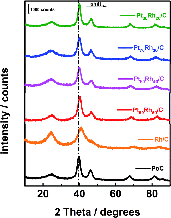 | ||
| Fig. 1 XRD patterns of the carbon supported PtxRhy materials prepared from the revisited BAE method. | ||
Table 1 summarizes the data related to the structural properties and the morphology (Fig. SI-1†) of the PtxRhy/C catalysts obtained by the BAE surfactant-free route. In comparison with recent literature, the proposed synthetic approach displays a good correlation of crystallite size values and permitted to recover lower particle sizes, which is synonymous to a gain of surface area and thus, an increase of the catalytic activity of the resulting electrode materials.35 Fig. 2A illustrates a TEM micrograph and a particle EDX analysis (Fig. 2B) for the Pt50Rh50/C catalyst. The TEM images show that the catalyst particles are well dispersed. The formation of Pt and Rh alloy is evidenced by EDX spectra which results were summarized in Table 1. The other PtxRhy/C compositions are depicted in Fig. SI-4† for comparison. As an example, the impregnation route led to PtxRhy/C materials with crystallite sizes comprised between 5 and 12 nm diameter.28,49 It can be also noticed in Table 1 an increase in the alloying degree50–52 in the PtxRhy/C catalysts as a function of the Rh content, which may be deduced from the lattice contraction with an incorporation of smaller Rh atoms into the Pt fcc-structure during the synthesis process.53,54
| Catalyst | Experimental composition (EDX) | Crystallite size (XRD) (nm) | Particle size (TEM) (nm) | 2θ (degree) | Lattice parameter (nm) | Alloying degree (%) |
|---|---|---|---|---|---|---|
| Pt/C | — | 2.8 | 3.0 | 39.58 | 0.3920 | — |
| Rh/C | — | 2.9 | 3.1 | 40.04 | 0.3790 | — |
| Pt50Rh50/C | Pt49Rh51/C | 2.6 | 2.8 | 39.87 | 0.3861 | 51 |
| Pt60Rh40/C | Pt65Rh35/C | 2.4 | 3.0 | 39.98 | 0.3873 | 42 |
| Pt70Rh30/C | Pt74Rh26/C | 3.0 | 3.1 | 39.76 | 0.3892 | 20 |
| Pt80Rh20/C | Pt78Rh22/C | 3.4 | 3.6 | 39.99 | 0.3891 | 20 |
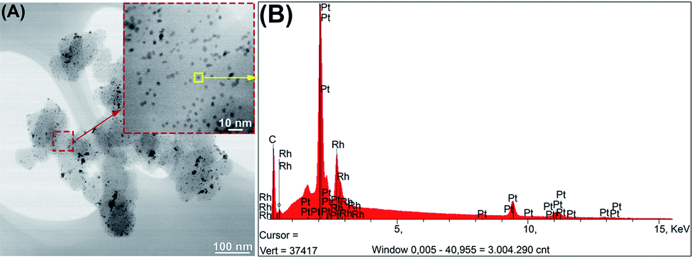 | ||
| Fig. 2 (A) TEM images for Pt50Rh50/C material. (B) EDX spectra of Pt50Rh50/C particle. | ||
As the measurements above reveal that the Pt50Rh50/C catalyst contains the highest alloying degree and as its physical properties (good dispersion and distribution size of the particles) are well correlated with the electrochemical ones (highest SECSA), the XPS analysis is first addressed to probe its surface chemical composition.
Table 2 summarizes the surface composition analyses based on the intensities of XPS peaks. The results indicated that Pt/Rh atomic ratios are quite different from the nominal values. This can be attributed mainly to the difference in the reduction potentials between Rh and Pt (for Rh E0 ∼ 0.4 V and Pt E0 ∼ 0.74 V in the presence of chloride ions) affecting the reduction species in case of simultaneous process, like in BAE method.55,56
| Binding energy/(eV) | Corresponding band | Species | Relative atomic percentage (%) Pt50Rh50/C |
|---|---|---|---|
| 71.4–75 | Pt 4f | Pt metallic | 0.9 |
| 72.4–75.7 | Pt2+ (PtO) | 0.3 | |
| 74.1–77.5 | Pt oxide (PtO2) | 0.3 | |
| 496.8 | Rh 3p3/2 | Rh metallic | 0.6 |
| 499.8 | Rh2O3 | 0.5 | |
| 284.4 | C 1s | C–C, C–H | 67.3 |
| 285.6 | C–O | 4.2 | |
| 286.7 | C![[double bond, length as m-dash]](https://www.rsc.org/images/entities/char_e001.gif) O O |
8.9 | |
| 289 | OC–O |
13.8 | |
| 531 | O 1s | 4.3 | |
| Ratio Pt/Rh 1.25 |
2.2 Electrochemical characterization of the PtxRhy/C catalysts
Fig. 3 depicts the cyclic voltammograms (CVs) of the targeted Pt50Rh50/C electrode, which is compared with those of Pt/C and Rh/C alone; the CVs of the other PtxRhy/C compositions are depicted in Fig. SI-6† for comparison. All the current values were normalized with respect to the metal loading deposited onto the conducting support for evaluating similarly the mass activity of the prepared electrodes. One observes clearly the two following beneficial features in Fig. 3f displaying the ethanol oxidation reaction (EOR) at the bimetallic Pt50Rh50/C electrode surface: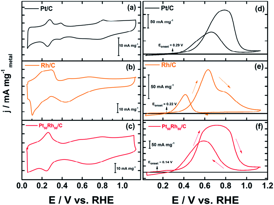 | ||
| Fig. 3 Voltammograms (CVs) of Pt and Rh based electrode materials prepared from the revisited BAE route. These CVs were recorded at room temperature and 10 mV s−1 and in 1 mol L−1 NaOH, in the absence (a, b and c) and the presence of 0.2 mol L−1 ethanol (d, e and f). | ||
(i) the fuel oxidation starts earlier (at 0.14 V) than its oxidative transformation on Pt/C (0.29 V) or on Rh/C (0.22 V vs. RHE). This shift toward lower potential values is well-known and attributed to the electronic effect herein evidenced both with the 51% alloying degree (XRD) and the shift observed in the binding energies of Pt 4f (XPS);3,14,29
(ii) at the same time, the 2.5 times increase in the current densities, compared to those on Pt/C, reveals a surface structure effect due to the presence of Rh atoms on the Pt based structure.
The EOR on the Pt50Rh50/C electrode during the forward scan covers a large potential domain. It hides various peaks at different Pt and Rh surface states, which involve reactive oxygenated species for enhancing ethanol oxidation through the bifunctional or Langmuir–Hinshelwood mechanisms. Interestingly, Fig. 3e shows a remarkable ethanol oxidation at the surface of Rh/C which was reported to be practically inactive towards the EOR in acid media.17,57 This activity of the Rh/C catalyst may be due to an ability of hydroxides formation at low potential on the material surface in alkaline medium (Fig. 3b). Taking into account only the reaction products detected by chromatographic analysis, a general mechanism for the conversion of ethanol to acetate on Pt50Rh50/C can be proposed according to the following equation:
 | (1) |
In alkaline medium, the reaction can take place at both Pt and Rh sites, since in Fig. 3e and f, it can be seen that ethanol is reactive on the two metals comprising the bimetallic anode. On the other hand, the increase in the carbonate concentration can undoubtedly be explained by the presence of Rh which provides a beneficial effect to Pt. It can be assumed that during the dissociative adsorption of ethanol, a bifunctional catalysis occurs to facilitate the desorption of poison species such as CO, as follows:
| Pt–COads + Rh–OHads + 3HO− → CO2−3 + 2H2O + e− | (2) |
It was reported that bridge CO adsorbs on Rh,38 and in this case the CO oxidative removal can be achieved with the contribution of neighboring Pt:
| Rh–CO–Rh + Pt–OHads + 3HO− → CO2−3 + 2H2O + e− | (3) |
Chronoamperometric measurements were also depicted in ESI (Fig. SI-7).† Although over the long term the activities of all catalysts are undifferentiated, Pt50Rh50 has the highest current densities within the first ten minutes.
2.3 Electrochemical performances of PtxRhy/C in DEFC
The direct ethanol fuel cell (DEFC) testing was undertaken in a home-made Teflon cell. Although the two compartments were separated with an AEM (from Fumatech) as reported recently,58 and here showed in the ESI,† the electrode materials were not coated on the membrane as a MEA; the investigation is herein focused on the behavior of each component during the operation of the EOR and the analysis of electrolytic solution by liquid chromatography to obtain the reaction products distribution. On this way, a reference electrode (AgCl/Ag/Cl−) was included in each compartment for recording separately the polarization curves of each electrode (Fig. 3). The Pt50Rh50/C catalyst deposited onto a carbon Toray paper composes the anode in the two performed testing. In Fig. 4a, the Pt/C prepared from the BAE method is used as cathode. As can be noticed, the oxygen reduction reaction (ORR) polarization curve starts at potential ca. 0.95 V vs. RHE while that of the EOR is at ca. 0.26 V vs. RHE. Beyond 1000 μA cm−2, the polarization curve of the cathode decreases dramatically, while that of the anode profile increases resulting in a cell voltage drop.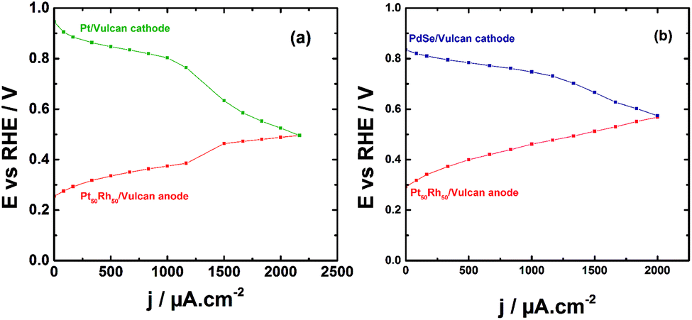 | ||
| Fig. 4 E–j polarizations curves obtained at the electrodes of a DEFC operating at room temperature and in alkaline medium. (a) (−) Pt50Rh50/C/1.0 mol L−1 ethanol//1.0 mol L−1 NaOH, O2/Pt/C (+); (b) (−) Pt50Rh50/C/1.0 mol L−1 ethanol//1.0 mol L−1 NaOH, O2/PdSe/C (+). | ||
HPLC analysis of the electrolytic solution in each compartment allowed to explain that the unexpected behavior in the ORR curve was due to the ethanol crossover through the membrane to start depolarizing the Pt/C cathode. Therefore, a selenium-based catalyst well-known for its alcohol tolerance,59,60 (herein PdSe/C), was used in place of Pt/C, which mitigated the depolarization of the cathode as can be noticed in Fig. 4b. The polarization curves have similar profiles than those obtained by Fujiwara et al.61 with a PtRu anode in a real fuel cell.
Fig. 5 depicts the cell voltage profile of the DEFC operating in alkaline medium and in which the Pt50Rh50/C and PdSe/C catalysts constitute the anode and the cathode, respectively. The power density reaches an optimum of 343 μW cm−2 at 1250 μA cm−2; furthermore, the open circuit voltage (OCV) obtained at 25 °C is 0.58 V. This value is 0.1 V higher than that obtained by Soares et al.12 in acid medium at 80 °C with a Pt80Rh20/C anode catalyst (40 wt% metal loading).
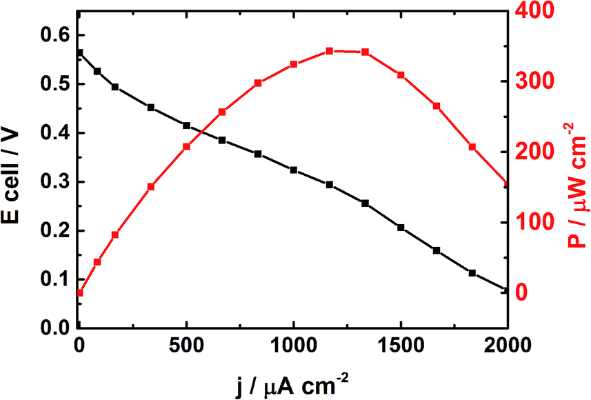 | ||
| Fig. 5 Electrochemical performances of a DEFC at 25 °C using Pt50Rh50/C (0.13 mg cm−2) and PdSe/C (0.13 mg cm−2) as anode and cathode catalysts, respectively; the anodic compartment contains 1 mol L−1 NaOH and 1 mol L−1 ethanol separated to the cathodic one by an AEM from Fumatech. | ||
2.4 Determination of the reaction products of ethanol oxidation
Considering the remarkable driving force obtained herein as compared to the literature, analysis of the resulting reaction production should be addressed. Therefore, a chronoamperometry experiment was undertaken at 0.6 V vs. RHE for 4 hours in a 1 mol L−1 NaOH electrolytic solution containing 0.2 mol L−1 ethanol. The refractive index detector (RID) enabled to determine 65% conversion of ethanol. The concentration of carbonate, which is the form of CO2 in basic solution, was also quantified thanks to this RID. It can be observed in Table 3 that the products distribution is strongly associated with the Rh content in the bimetallic anode composition; and whatever the electrode, acetate, a 4-electron reaction product, remains the major produced compound. The carbonate production is specifically high and attains 15.3% on the Pt50Rh50/C surface instead of 4% on Pt/C. This trend is in fair line with the previous results showing that the Rh content strongly contributes to the activity of the catalyst, and particularly, to the C–C bond cleavage.17,31,49 Although their distribution is varying depending on the electrocatalyst, the two reported pathways of the EOR must be considered on the PtxRhy/C anodes:26,27,62,63| Catalyst | Ethanol consumed (mol L−1) | Reaction products | Mass balance (%) | ||
|---|---|---|---|---|---|
| Acetaldehyde (%) | Acetate (%) | CO32− (%) | |||
| Pt/C | 0.03 | — | 91.5 | 4.5 | 95.0 |
| Pt50Rh50/C | 0.13 | — | 33.8 | 15.3 | 49.1 |
| Pt60Rh40/C | 0.09 | — | 37 | 10.5 | 47.5 |
| Pt70Rh30/C | 0.05 | — | 55 | 4.5 | 59.5 |
| Pt80Rh20/C | 0.03 | — | 66 | 5.5 | 71.5 |
(i) the acetate formation that involves 4 electrons and keeps the initial skeleton of the molecule. It should be noted that acetaldehyde was not detected in the electrolytic solution. However, at the end of the experiment, the electrolytic solution was slightly yellow suggesting the polymerization of acetaldehyde through aldol condensation.64 To improve the mass balance the remaining reaction products must still be determined, which must concern a low amount of compounds because a large part of acetaldehyde is either transformed electrochemically into acetate or a nucleophilic attack by HO− leads to acetate suddenly.16 In situ infrared spectroscopy measurements are ongoing to scrutinize the eventual existence of this intermediate.
(ii) The second route involves the C–C bond cleavage. One of the two carbonaceous groups contains the alcohol function; one can easily imagine its conversion to CO and then, carbonate at higher potential values. But the other one (CHx) which is difficult to oxidize to CO or carbonate at room temperature may induce a deficiency in the mass balance.16,65 Other complementary advanced techniques are needed to scrutinize the eventual existence of this CHx intermediate or final product.
3. Experimental
3.1 Chemicals
Chloroplatinic acid hydrate (H2PtCl6·6H2O, ≥37.5% Pt basis), rhodium chloride (RhCl3·xH2O, 38–40% Rh basis), potassium bromide (KBr, 99%), acetaldehyde and sodium borohydride (NaBH4) were purchased from Sigma-Aldrich and used as received. Carbon Vulcan XC 72R from Cabot was utilized as conducting substrate to dilute the noble elements amounts in the catalyst compositions. Nafion® 1100 EW 5% wt suspension, in a mixture of aliphatic alcohols and water permitted the catalytic ink formulation. Acetic acid, acid formic and isopropanol used was purchased from Merck. All the solutions were prepared with Millipore Milli-Q® water (18.2 MΩ cm at 20 °C).3.2 Catalysts synthesis
The bromide anion exchange (BAE) method can be explained as the reduction of a precursor metal ion (in the complex state) in aqueous solution using bromide ion as capping agent. While the parameters such as the metal salt concentration, the volume of reaction, the amount of reducing agent and the temperature were set as reported in the state-of-the-art BAE protocol9,47 (1.0 mmol L−1, 100.0 mL, 15-fold excess and 40.0 °C, respectively), the ratio ϕ = n(KBr)/n(metal(s)) was slightly modified and varied from 0.0 to 6.5 in order to optimize the preparation of the Pt based electrode materials. Accordingly, the prepared catalysts are described as PtϕBr/C in the text. Thus, 20.0 mg of metal salt was first dissolved in 100.0 mL water followed by the addition of experimental ratio ϕ of potassium bromide under vigorous stirring for 1 h. Carbon Vulcan was then added to the solution and sonicated during 45 min for complete homogenization. Afterwards, sodium borohydride (15-fold excess in cold water solution) was added dropwise to the mixture and stirred for 2 h at 40 °C. The suspension was filtered and exhaustively washed with water. The final powder was dried for 24 h at 40 °C before use. Vulcan XC 72R carbon support is used in all catalysts and was subjected to thermal treatment at 900 °C in argon atmosphere for 5 h in a tubular oven.12 Therefore, the PtxRhy/C catalysts were prepared with different molar compositions (x![[thin space (1/6-em)]](https://www.rsc.org/images/entities/char_2009.gif) :y = 100:0; 80:20; 70:30; 60:40; 50:50). All the catalysts were prepared keeping a 20 wt% metal loading. The characterization and determination of the best ratio ϕ composition were undertaken from UV-visible spectroscopy (UV-vis), X-ray diffraction (XRD), CO stripping and cyclic voltammetric (CV) measurements.
:y = 100:0; 80:20; 70:30; 60:40; 50:50). All the catalysts were prepared keeping a 20 wt% metal loading. The characterization and determination of the best ratio ϕ composition were undertaken from UV-visible spectroscopy (UV-vis), X-ray diffraction (XRD), CO stripping and cyclic voltammetric (CV) measurements.
3.3 Physicochemical characterization
Ultraviolet-visible spectroscopy (UV-vis) measurements were performed with a spectrophotometer Agilent model Carry-500. X-ray diffraction patterns of the catalysts were obtained with an X-ray diffractometer (Bruker-D2 Phaser) operating with Cu Kα radiation (λ = 0.15406 nm) generated at 30 kV and 10 mA. The parameters were kept constant during the analysis: 2θ range = 20–90°, and step = 0.025° s−1. The composition phase of the materials was achieved by fitting the experimental angular range of interest to the pseudo-Voigt function per crystalline peak with the Profile Plus Executable refinement program (Siemens AG). Debye–Scherrer equation was used to estimate the crystallite size, and the unit cell parameters were determined using the least-squares method by a UFit. exe v1.3-1992 software. The metal-loading of each as-prepared sample was estimated by thermogravimetric analysis (TGA) performed on a Q600 TA Instruments SDT2960 under synthetic air using a 10 °C min−1 heating rate from 20 to 900 °C. Energy-dispersive X-ray spectroscopy (EDX) was performed in a Leica Zeiss LEO 440 to check the homogeneity of the local elemental composition in each prepared material. Additionally, surface morphology was investigated with a High-Resolution Transmission Electron Microscopy (HRTEM) using a TECNAI G2F20 electron microscope in bright and dark field modes coupled with EDX analysis. X-ray photoelectron spectroscopy (XPS) was used to probe and characterize the surface and oxidation states of the prepared material samples. Analyses were performed on a Kratos Axis Ultra DLD spectrometer equipped with a monochromatic Al Kα X-ray source (1486.6 eV) operating at 15 kV and 10 mA (150 W). The base pressure of the instrument was 9 × 10⁻⁸ Pa. The sample powder was pressed in a copper holder of 3 mm diameter and introduced into the preparation chamber after being outgassed overnight. The analysis spot size is approximately 300 μm × 700 μm and the pass energy is 20 eV for recording high-resolution spectra. The C 1s spectra used as internal reference is centered at 284.6 eV. Spectra were fitted with CasaXPS software (version 2.3.17). Shirley background has been chosen and asymmetric Gaussian–Lorentzian profile functions were used to fit the spectra.3.4 Electrochemical characterization of the electrode materials
All the glassware was first thoroughly cleaned in an acidic potassium permanganate solution and then an acidic/hydrogen peroxide solution to remove any organic/inorganic impurities that may result from the previous experiments. After washing, the glassware was rinsed with hot water to remove any remaining species. Otherwise, a catalytic ink was prepared with 2.0 mg of the catalyst powder which was dispersed in a solution composed of water (100 μL), isopropanol (95 μL) and a Nafion® suspension (5 μL) (5 wt% in aliphatic alcohol Aldrich). This ink was homogenized in an ultrasound bath for 30 min. Finally, 3 μL of the ink was deposited uniformly onto a glassy carbon (GC) disk (3 mm diameter) previously polished with alumina and dried at room temperature. The experiments were carried out using an Autolab Potentiostat (PGSTAT302N, Metrohm); all the solutions were prepared by using ultra-pure water (Milli-Q) and then purged with N2 gas for nearly 15 min before starting the electrochemical measurements. Cyclic voltammetry (CV) and chronoamperometry (CA) were performed in a conventional three-electrode cell. Hg/HgO/OH− (1.0 mol L−1 NaOH) and a platinized platinum wire were used as the reference and counter electrodes, respectively. For comparing easily, all potentials are associated with the reversible hydrogen electrode (RHE) from the Hg/HgO reference electrode (−0.965 V vs. RHE). The CVs were recorded by potential cycling from 0.05 to 1.15 V vs. RHE in solution containing 0.20 mol L−1 ethanol (Merck) and without ethanol at a 10 mV s−1 scan rate. The chronoamperometry tests were conducted for 30 min and at 0.60 V vs. RHE in alkaline solution containing 0.20 mol L−1 ethanol. The potential was recorded between 0.05 to 1.15 V vs. RHE at a 10 mV s−1 scan rate. The currents obtained during the electrochemical experiments were normalized with the mass of metals (Pt + Rh) contained in each deposited catalyst.3.5 Analysis of reaction products by high-performance liquid chromatography
The performance of PtxRhy/C catalysts for ethanol conversion was investigated by electrolysis experiments realized in potentiostatic conditions. The potential was fixed in 0.60 V vs. RHE for 4 hours. Aliquots were collected every 30 min and injected in high-performance liquid chromatography (HPLC, from Shimadzu, model LC-10AT) equipped with a double on-line detection system i.e. a UV-vis (λ = 210 nm) detector followed by a refractive index (RID-10A). The apparatus was also composed of an automatic injector with a 20 μL sample loop, and an ion exclusion column (Aminex HPX-87H, from BioRad). The mobile phase was a solution of sulfuric acid (3.33 mmol L−1 H2SO4) at a 0.6 mL min−1 flow rate. The reaction products were quantitatively determined by comparing their retention times with those pure commercial standards injected under the same isocratic analysis conditions (external calibration).3.6 Cell voltage performance
The driving force of a direct ethanol fuel cell was evaluated in a home-made single Teflon two-compartment cell. The current–potential testing was implemented with the Pt50Rh50/C catalyst as anode with a 0.13 mg cm−2 metal loading. The catalytic ink was prepared by mixing the required material sample amount with 375 μL Milli-Q® water and 50 μL Nafion® 5 wt%. The mixture was homogenized ultrasonically before its deposition onto the both sides of a carbon Toray substrate. The cathode was composed of a palladium–selenium (PdSe/C) catalyst, which was selected for its more ethanol tolerance in case of fuel crossover to the cathodic compartment. Anion exchange membrane (AEM, Fumasep FAA, from Fumatech) pre-treated in a 0.1 mol L−1 NaOH solution, was used to separate physically the two compartments and to insure the current relay between the electrodes. The DEFC operated with 1.0 mol L−1 NaOH supporting electrolyte at 25 °C in each compartment; while the anodic side contained a 1.0 mol L−1 ethanol solution, oxygen was supplied in the cathodic one.4. Conclusions
In this work a revisited surfactant-free BAE method was used to synthesize PtxRhy/C catalysts that turned out to be noticeably active towards ethanol oxidation reaction. The Pt50Rh50/C catalyst was used as anode for undertaking a DEFC in which the ORR was catalyzed on a PdSe/C cathode, which is ethanol tolerant. The DEFC performed with a remarkable open circuit voltage, indicating how promising is the catalyst prepared with a synthetic method without any poisoning of the active site by heavy organics from the surfactant. Actually, the obtained PtRh nanoparticles were well dispersed on the carbon substrate, with a small distribution size (3.0–3.8 nm), which is associated with a high specific electrochemical active surface area. The physicochemical properties of the anode such as the high alloying degree may explain the beneficial ensemble (electronic and geometric) effects on the EOR. As a consequence, the presence of the Rh content matches well with the Pt atoms, which induces a dissociative ethanol adsorption to produce almost 4 times, more carbonate on Pt50Rh50/C than on Pt/C. Nevertheless, advanced techniques more sensitive than liquid chromatography are needed to improve the mass balance. In situ infrared spectroscopy measurements are ongoing to contribute to identifying some intermediates in low concentrations.Conflicts of interest
There are no conflicts to declare.Acknowledgements
The authors thank CAPES-COFECUB (project no. 914/18) and CNPq for their financial support. “This study was financed in part by the Coordenação de Aperfeiçoamento de Pessoal de Nível Superior – Brasil (CAPES) – Finance Code 001”. The authors from IC2MP thank the European Union (ERDF) and Région Nouvelle-Aquitaine for their support. The authors were grateful to the Prof. Dr N. Alonso-Vante for providing the PdSe/C cathode material.References
- M. A. Abdelkareem, K. Elsaid, T. Wilberforce, M. Kamil, E. T. Sayed and A. Olabi, Sci. Total Environ., 2020, 141803 Search PubMed.
- M. Z. F. Kamarudin, S. K. Kamarudin, M. S. Masdar and W. R. W. Daud, Int. J. Hydrogen Energy, 2013, 38, 9438–9453 CrossRef CAS.
- S. P. S. Badwal, S. Giddey, A. Kulkarni, J. Goel and S. Basu, Appl. Energy, 2015, 145, 80–103 CrossRef CAS.
- H. V. Amorim, M. L. Lopes, J. V. de Castro Oliveira, M. S. Buckeridge and G. H. Goldman, Appl. Microbiol. Biotechnol., 2011, 91, 1267–1275 CrossRef CAS.
- W. Vielstich, J. Braz. Chem. Soc., 2003, 14, 503–509 CrossRef CAS.
- R. M. Altarawneh, T. M. Brueckner, B. Chen and P. G. Pickup, J. Power Sources, 2018, 400, 369–376 CrossRef CAS.
- C. Zhu, S. Guo and S. Dong, Adv. Mater., 2012, 24, 2326–2331 CrossRef CAS.
- L. Wang, J.-J. Zhai, K. Jiang, J.-Q. Wang and W.-B. Cai, Int. J. Hydrogen Energy, 2015, 40, 1726–1734 CrossRef CAS.
- Y. Holade, N. Sahin, K. Servat, T. Napporn and K. Kokoh, Catalysts, 2015, 5, 310–348 CrossRef CAS.
- W. J. Zhou, W. Z. Li, S. Q. Song, Z. H. Zhou, L. H. Jiang, G. Q. Sun, Q. Xin, K. Poulianitis, S. Kontou and P. Tsiakaras, J. Power Sources, 2004, 131, 217–223 CrossRef CAS.
- M. A. F. Akhairi and S. K. Kamarudin, Int. J. Hydrogen Energy, 2016, 41, 4214–4228 CrossRef CAS.
- L. A. Soares, C. Morais, T. W. Napporn, K. B. Kokoh and P. Olivi, J. Power Sources, 2016, 315, 47–55 CrossRef CAS.
- Y. H. Ahmad, A. T. Mohamed, A. Alashraf, M. Matalqeh, A. El-Shafei, S. Y. Al-Qaradawi and A. S. Aljaber, Appl. Surf. Sci., 2020, 508, 145222 CrossRef.
- E. S. Valério Neto, M. A. Gomes, G. R. Salazar-Banda and K. I. B. Eguiluz, Int. J. Hydrogen Energy, 2018, 43, 178–188 CrossRef.
- S. Beyhan, J.-M. Léger and F. Kadırgan, J. Power Sources, 2013, 242, 503–509 CrossRef CAS.
- S. Beyhan, J.-M. Léger and F. Kadırgan, Appl. Surf. Sci., 2014, 321, 426–431 CrossRef CAS.
- E. H. Fontes, R. M. Piasentin, J. M. S. Ayoub, J. C. M. da Silva, M. H. M. T. Assumpção, E. V. Spinacé, A. O. Neto and R. F. B. de Souza, Mater. Renew. Sustain. Energy, 2015, 4, 3 CrossRef.
- H. Zhang, H.-R. Tan, S. Jaenicke and G.-K. Chuah, J. Catal., 2020, 389, 19–28 CrossRef CAS.
- Y. Kang, W. Wang, Y. Pu, J. Li, D. Chai and Z. Lei, Chem. Eng. J., 2017, 308, 419–427 CrossRef CAS.
- F. L. S. Purgato, P. Olivi, J. M. Léger, A. R. de Andrade, G. Tremiliosi-Filho, E. R. Gonzalez, C. Lamy and K. B. Kokoh, J. Electroanal. Chem., 2009, 628, 81–89 CrossRef CAS.
- S. Q. Song, W. J. Zhou, Z. H. Zhou, L. H. Jiang, G. Q. Sun, Q. Xin, V. Leontidis, S. Kontou and P. Tsiakaras, Int. J. Hydrogen Energy, 2005, 30, 995–1001 CrossRef CAS.
- H. Zhang, J. He, C. Zhai and M. Zhu, Chin. Chem. Lett., 2019, 30, 2338–2342 CrossRef CAS.
- C. Zhai, M. Sun, L. Zeng, M. Xue, J. Pan, Y. Du and M. Zhu, Appl. Catal., B, 2019, 243, 283–293 CrossRef CAS.
- L. Lin, W. Sheng, S. Yao, D. Ma and J. G. Chen, J. Power Sources, 2017, 345, 182–189 CrossRef CAS.
- J. Y. Z. Chiou, C.-L. Lee, K.-F. Ho, H.-H. Huang, S.-W. Yu and C.-B. Wang, Int. J. Hydrogen Energy, 2014, 39, 5653–5662 CrossRef CAS.
- P. Mukherjee, P. S. Roy and S. K. Bhattacharya, Int. J. Hydrogen Energy, 2015, 40, 13357–13367 CrossRef CAS.
- C. V. S. Almeida, N. A. Galiote, K. I. B. Eguiluz, G. R. Salazar-Banda, V. Del Colle and G. Tremiliosi-Filho, Electrochim. Acta, 2020, 351, 136223 CrossRef CAS.
- P. Wang, Y. Wen, S. Yin and N. Wang, Int. J. Hydrogen Energy, 2017, 42, 24689–24696 CrossRef CAS.
- F. Zhu, K. Tu, L. Huang, X. Qu, J. Zhang, H. Liao, Z. Zhou, Y. Jiang and S. Sun, Electrochim. Acta, 2018, 292, 208–216 CrossRef CAS.
- J. P. I. De Souza, S. L. Queiroz, K. Bergamaski, E. R. Gonzalez and F. C. Nart, J. Phys. Chem. B, 2002, 106, 9825–9830 CrossRef CAS.
- L. C. Silva-Junior, G. Maia, R. R. Passos, E. A. de Souza, G. A. Camara and M. J. Giz, Electrochim. Acta, 2013, 112, 612–619 CrossRef CAS.
- S. L. Medway, C. a. Lucas, A. Kowal, R. J. Nichols and D. Johnson, J. Electroanal. Chem., 2006, 587, 172–181 CrossRef CAS.
- C.-Y. Huang, J.-S. Lin, W.-H. Pan, C.-M. Shih, Y.-L. Liu and S. J. Lue, J. Power Sources, 2016, 303, 267–277 CrossRef CAS.
- S. Beyhan, C. Coutanceau, J.-M. Léger, T. W. Napporn and F. Kadırgan, Int. J. Hydrogen Energy, 2013, 38, 6830–6841 CrossRef CAS.
- S. Sen Gupta and J. Datta, J. Electroanal. Chem., 2006, 594, 65–72 CrossRef CAS.
- J. Bai, X. Xiao, Y.-Y. Xue, J.-X. Jiang, J.-H. Zeng, X.-F. Li and Y. Chen, ACS Appl. Mater. Interfaces, 2018, 10, 19755–19763 CrossRef CAS.
- Y.-W. Lee and K.-W. Park, Catal. Commun., 2014, 55, 24–28 CrossRef CAS.
- L. Rao, Y.-X. Jiang, B.-W. Zhang, Y.-R. Cai and S.-G. Sun, Phys. Chem. Chem. Phys., 2014, 16, 13662–13671 RSC.
- A. Kowal, S. L. Gojković, K. S. Lee, P. Olszewski and Y. E. Sung, Electrochem. Commun., 2009, 11, 724–727 CrossRef CAS.
- M. Harada and H. Einaga, J. Colloid Interface Sci., 2007, 308, 568–572 CrossRef CAS.
- E. R. Essinger-Hileman, D. DeCicco, J. F. Bondi and R. E. Schaak, J. Mater. Chem., 2011, 21, 11599 RSC.
- J.-H. Choi, K.-W. Park, I.-S. Park, W.-H. Nam and Y.-E. Sung, Electrochim. Acta, 2004, 50, 787–790 CrossRef CAS.
- L. Li, C. Tian, J. Yang, X. Zhang and J. Chen, Int. J. Hydrogen Energy, 2015, 40, 14866–14874 CrossRef CAS.
- L. Huang, J.-Y. Sun, S.-H. Cao, M. Zhan, Z.-R. Ni, H.-J. Sun, Z. Chen, Z.-Y. Zhou, E. G. Sorte, Y. J. Tong and S.-G. Sun, ACS Catal., 2016, 6, 7686–7695 CrossRef CAS.
- Y. Holade, R. G. da Silva, K. Servat, T. W. Napporn, C. Canaff, A. R. de Andrade and K. B. Kokoh, J. Mater. Chem. A, 2016, 4, 8337–8349 RSC.
- M.-Y. Wang, X.-Y. Li and L.-N. He, Curr. Opin. Green Sustain., 2018, 13, 123–129 CrossRef.
- Y. Holade, K. Servat, T. W. Napporn and K. B. Kokoh, Electrochim. Acta, 2015, 162, 205–214 CrossRef CAS.
- S. A. Neto, T. F. M. Moreira and P. Olivi, Int. J. Hydrogen Energy, 2019, 44, 8079–8088 CrossRef CAS.
- J. Lu, L. Zhang, S. Jing, L. Luo and S. Yin, Int. J. Hydrogen Energy, 2017, 42, 5993–5999 CrossRef CAS.
- S. Mukerjee and R. C. Urian, Electrochim. Acta, 2002, 47, 3219–3231 CrossRef CAS.
- R. Loukrakpam, Q. Yuan, V. Petkov, L. Gan, S. Rudi, R. Yang, Y. Huang, S. R. Brankovic and P. Strasser, Phys. Chem. Chem. Phys., 2014, 16, 18866–18876 RSC.
- Z. Liu, J. Y. Lee, W. Chen, M. Han and L. M. Gan, Langmuir, 2004, 20, 181–187 CrossRef CAS.
- M. J. Lambregts and S. Frank, Talanta, 2004, 62, 627–630 CrossRef CAS.
- M.-k. Min, J. Cho, K. Cho and H. Kim, Electrochim. Acta, 2000, 45, 4211–4217 CrossRef CAS.
- J. F. Moulder, Physical Electronics, 1995, pp. 230–232 Search PubMed.
- S. z. cefik, Appl. Spectrosc., 54, 1716–1718 Search PubMed.
- C. Zhu, B. Lan, R.-L. Wei, C.-N. Wang and Y.-Y. Yang, ACS Catal., 2019, 9, 4046–4053 CrossRef CAS.
- Y. Holade, K. Servat, T. W. Napporn, C. Morais, J.-M. Berjeaud and K. B. Kokoh, ChemSusChem, 2016, 9, 252–263 CrossRef CAS.
- S. M. Unni, J. M. Mora-Hernandez, S. Kurungot and N. Alonso-Vante, Chemelectrochem, 2015, 2, 1339–1345 CrossRef CAS.
- A. A. Serov, S.-Y. Cho, S. Han, M. Min, G. Chai, K. H. Nam and C. Kwak, Electrochem. Commun., 2007, 9, 2041–2044 CrossRef CAS.
- N. Fujiwara, Z. Siroma, S.-i. Yamazaki, T. Ioroi, H. Senoh and K. Yasuda, J. Power Sources, 2008, 185, 621–626 CrossRef CAS.
- I. A. Khan, L. Khan, S. I. Khan and A. Badshah, Electrochim. Acta, 2020, 349, 136381 CrossRef CAS.
- C. D. Silva, P. G. Corradini, V. Del Colle, L. H. Mascaro, F. H. B. de Lima and E. C. Pereira, Electrochim. Acta, 2020, 354, 136674 CrossRef CAS.
- J. Guo, R. Chen, F.-C. Zhu, S.-G. Sun and H. M. Villullas, Appl. Catal., B, 2018, 224, 602–611 CrossRef CAS.
- S. Beyhan, J.-M. Léger and F. Kadırgan, Appl. Catal., B, 2014, 144, 66–74 CrossRef CAS.
Footnote |
| † Electronic supplementary information (ESI) available. See DOI: 10.1039/d0ra06570f |
| This journal is © The Royal Society of Chemistry 2020 |