 Open Access Article
Highly conductive and transient tracks based on silver flakes and a polyvinyl pyrrolidone composite†
Su Ding *,
Qingfeng Cai,
Jintao Mao,
Fei Chen
 ,
Li Fu,
Yanfei Lv and
Shichao Zhao*
College of Materials and Environmental Engineering, Hangzhou Dianzi University, 310018 Hangzhou, P. R. China. E-mail: dingsu@hdu.edu.cn; zhaoshichao@hdu.edu.cn
First published on 7th September 2020
Abstract
Transient electronics have been widely researched to solve the electronic waste (E-waste) issue. Although various transient materials and devices have been reported, the fabrication technique for transient conductors always uses expensive sputtering or evaporation processes. In this study, a silver flake (AgF) and polyvinyl pyrrolidone (PVP) composite is prepared for conductive and transient tracks. The AgF/PVP composite tracks are highly conductive with a resistivity of 8.9 mOhm cm after sintering at 80 °C for only 3 minutes. Impressively, the AgF/PVP tracks disintegrate in water in 3 minutes due to the fast dissolution of the water-soluble PVP. The transient behavior of the AgF/PVP tracks has potential in transient electronics as demonstrated in a light emitting diode (LED) circuit and antenna.
1 Introduction
Transient electronics can potentially suppress the electronic waste (E-waste) pollution, caused by the rapid development of consumer electronics, including phones, computers, and electric appliances.1–6 Normally, E-waste is disposed of via several methods, including dissolution in strong acids, burning and landfilling, all of which migrate chemical products into the receiving waters and food chains.1,7–9 Such processing is harmful to the environment and human health. In contrast, transient electronics are designed to operate for a certain duration and then self-deconstruct in water after finishing the task.10–13 Thus, transient devices are highly desirable for applications in zero-waste electronics, biomedical implant devices, and secure electronics.5,10,14–17Metals, which are essential in electrical devices, are used to form a conductive pattern on the printed circuit boards and as a connection material for the assembly of functional components.18–20 The waste of electric and electronic equipment (WEEE) consist of more than 60% metals, which are generally recycled by acid leaching and precipitative routes for economic reasons.21,22 Rogers group23 first reported the integration of silicon-based transient electronics using magnesium (Mg) for interconnections due to its excellent conductivity, rapid rate of hydrolysis and biocompatibility. The results show that the Mg trace (150 nm) was diffused in water after 3 hours, a duration much longer than that of soluble polymer substrates (normally in minutes).3,6 Subsequently, reactive dissolution of thin films of Mg alloy, Zn, Fe, W, and Mo in water is systematically studied to assess the potential applications in transient electronics. The dissolution of these thin films normally takes one week to several months and involves the fast degradation of the base metal and the disappearance of the residual oxides.24 The low dissolution rate of metals prolongs the transient duration of electronics. Additionally, the fabrication of thin metallic films always employs complex electron beam evaporation, magnetron sputtering or lithography techniques. Development of simple and scalable techniques is expected to fabricate transient conductors with short dissolution durations.
Organo–inorganic nanocomposites are promising in various fields, including photocatalysis, energy storage, capacitor, conductor, etc25–29. Incorporating functional moieties on nanomaterials offers a way to tailor the comprehensive performance of the composition.30–36 Huang's group9 reported a simple fabrication of Ag nanowire (AgNW) conductor on soluble polymer substrate as both electrodes of a transient alternating current electroluminescent (ACEL) device. The fabricated ACEL device can be thoroughly dissolved in water within 30 min. The AgNW and polymer composite conductor combines the advantages of both the metallic Ag and soluble polymer providing new method to fabricate transient conductors. In this paper, we fabricate silver flake (AgF) and polyvinyl pyrrolidone (PVP) conductive tracks and examine their potential for use in transient electronics. The raw material of AgFs in the as-prepared AgF/PVP conductive tracks is conveniently recyclable after dissolution in water and thus, superior to the conventional acid washing process used to recycle precious metals, such as Cu and Au. The AgF/PVP composite tracks sintered at 80 °C for 3 minutes show good electrical performance and transient behavior. The AgF/PVP composite track is successfully applied in a light emitting diode (LED) transient circuit, thus, demonstrating its potential use in more complex transient electronics.
2 Experiments
2.1 Fabrication of AgF/PVP conductive tracks
Polyvinylpyrrolidone (PVP, K30, Shanghai Aladdin Bio-Chem Technology Co., LTD, Shanghai, China) and Ag flakes (Bolong Silver Industry, Hunan, China) were used as purchased without further purification. PVP solution (20 wt% in ethanol) was prepared and mixed with AgF powder with different mass ratios to form Ag ink. The Ag ink was ultrasonic vibrated for 5 minutes and stirred by hand for several seconds to achieve homogeneous ink. Then, 80 μL Ag ink was dropped onto a glass substrate with size of 4 × 26 mm controlled by tapes. The ink-coated glass films were heated in an oven at 80 °C for 3 minutes to remove the ethanol. After peeling off the tapes, AgF/PVP conductive tracks were successfully obtained.2.2 Characterization of the AgF/PVP conductive tracks
The rheology experiments of the AgF/PVP ink were carried out at room temperature using a rotational rheometer (MCR52, Anton Paar). The viscosity properties of the ink were obtained by varying the shear rate from 30 to 500 s−1. The composition of the AgF/PVP conductive tracks were confirmed by X-ray diffraction (XRD, Miniflex600, Rigaku Corporation) and X-ray photoelectron spectroscopy (XPS, K-Alpha, Thermo Fisher Scientific). XRD patterns were recorded at room temperature with scanning speed of 5° min−1 from 10° to 80°. XPS results were amended using the C 1s peak at binding energy of 284.6 eV as reference. The morphology of the AgF/PVP conductive tracks was checked by scanning electron microscopy (SEM, Apreo, FEI). The elemental composition of the AgF/PVP track was monitored using the energy dispersive spectroscopy (EDS) equipped on the SEM. The thermal characterization of the AgF/PVP tracks was operated on a TGA/DSC analyzer (TGA/DSC LF1600, Mettler) under a nitrogen ambient atmosphere with a heating rate of 10 °C min−1, from 25 to 800 °C.2.3 Properties and applications of the AgF/PVP conductive tracks
3 Results and discussion
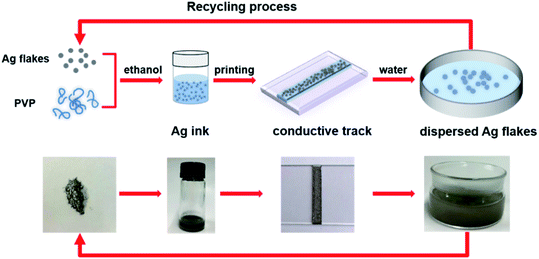
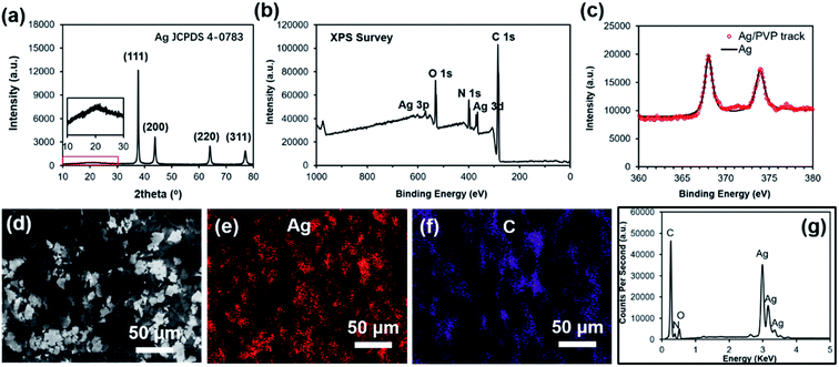
Fig. 1 is a schematic illustration of the experiments. The AgFs are mixed with PVP to form Ag ink, followed by the coating of glass substrates with the Ag ink. After a rapid sintering process, high-performance AgF/PVP tracks are achieved due to the excellent conductivity of AgFs. The AgF/PVP tracks can be readily dissolved in water owing to the addition of water-soluble PVP. The dissolved AgF/PVP composite is disintegrated into dispersed AgFs after tens of seconds of ultrasonic vibration, and can be commodiously recycled during the E-waste disposal process. Compared with the traditional acid leaching procedure, the expensive AgF/PVP conductive tracks can be more conveniently recycled. This proposal put forward a simple and effective strategy for fabricating conductive tracks in transient electronics and should be prioritized in the recycling process in the meantime.The composition and the morphology of AgF/PVP conductive tracks is examined as shown in Fig. 2. The XRD pattern of the AgF/PVP track with diffraction peaks at 2θ value 38.1°, 44.1°, 64.4° and 77.3° indexes to the {111}, {200}, {220} and {311} planes of Ag (JCPDS 4-0783). The broad band located around 22° corresponds to the amorphous PVP as reported in previous ref. 37. XPS measurement of survey spectra (Fig. 2(b)) shows the presence of C, N, O and Ag signals. High resolved XPS Ag 3d spectra of the AgF/PVP track and standard Ag are presented in Fig. 2(c). The XPS Ag 3d 5/2 and 3d 3/2 binding energies for AgFs appears at 368 and 374 eV, respectively, which is in good agreement with standard Ag values.38 In addition, there is no XPS peaks of AgO and Ag2O having binding energies at 367.33 eV and 367.62, respectively.39 The XRD and XPS results demonstrate the as-prepared tracks comprise Ag and PVP without other impurities. The AgFs are randomly dispersed on the surface and connect with each other in plane or through the 3-dimensional AgF network that is partially embedded in the PVP polymer as shown in Fig. 2(d). The energy-dispersive X-ray spectroscopy (EDS) images reveal the distribution of the AgFs and the PVP polymer on the surface. The Ag and C element mapping coincides with the sites of the grey flakes and the dark polymer in Fig. 2(d), respectively. Although the AgFs are partially separated by the insulated PVP polymer as shown in the EDS images, the AgFs join with other flakes to form conductive paths such that the resistivity of the AgF/PVP composite track is only 8.9 mOhm cm with only 40% AgFs, demonstrating the good connections of the AgFs in the 3-dimensional AgFs network. The conductivity of the AgF/PVP composite track is better than the previously reported values9,10,23 and can be further improved by adding more AgFs.
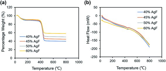
To study the effect of the quantity of the AgFs, various AgF/PVP composite tracks with different mass ratios are prepared and the corresponding properties are examined. Fig. S3† illustrate the viscosity curve for the AgF/PVP ink with various AgF concentrations. The steady viscosity is 31.3, 32,3, 32.7 and 34.9 mPa s for the AgF/PVP ink with 40%, 45%, 50% and 60% AgFs, respectively. The results show viscosity increase with increasing Ag concentration. The thermal stability of the AgF/PVP conductive track are characterized by TGA/DSC as shown in Fig. 3. There is a well defined weight loss for all the tracks at 400–460 °C at which temperature the DSC curves show endothermic peaks. The weight loss corresponds to the decomposition of the PVP polymer. The percentage weights are 39.8%, 44.6%, 50.1% and 58.0%, respectively for the AgF/PVP conductive tracks with 40%, 45%, 50% and 60% AgFs containments indicating the residuals are metallic Ag. Fig. 4 shows the morphology and resistivity of the AgF/PVP composite tracks with AgF contents of 40%, 45%, 50% and 60%. The original AgFs are several micrometers in size as presented in Fig. S1.† The AgF/PVP tracks have a smooth surface with AgFs uniformly dispersed in the PVP polymer as shown in Fig. 4. The AgFs inlay in the PVP polymer without discordant interfaces shows good adhesion between AgFs and PVP. When the AgF content is only 40%, the density of the AgFs on the surface of the composite is relatively low, and a small percent of the AgFs connect with each other. With increase in AgF containment (45% and 50%), the density of the AgFs obviously increases such that conductive paths can be formed in plane as marked in Fig. 4(b and c). A dense AgF network is formed with 60 wt% AgFs which helps to improve the conductivity. The resistivity of the AgF/PVP tracks at various mass ratios is given in Fig. 4(e). The resistivity is only 8.9 mOhm cm when 40% AgFs are added in the composite tracks, resulting in excellent electrical performance that is suitable for commercial conductors. The AgF/PVP conductive track also shows a good current carrying capacity (Fig. S4†). When the content of AgFs is imcreased to 45%, the resistance declines to 1.6 mOhm cm. The resistance further decreases to 567 μOhm cm and 510 μOhm cm if the addition of AgFs is improved to 50% and 60%, respectively. This result indicates that the conductivity of the AgF/PVP tracks is obviously improved when more AgFs are mixed in the composite because more conductive paths are built between the AgFs.
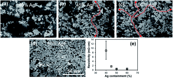 | ||
| Fig. 4 SEM images (a–d) and resistivity (e) of AgF/PVP conductive tracks with various AgF containments. (a) 40%, (b) 45%, (c) 50%, (d) 60%. | ||
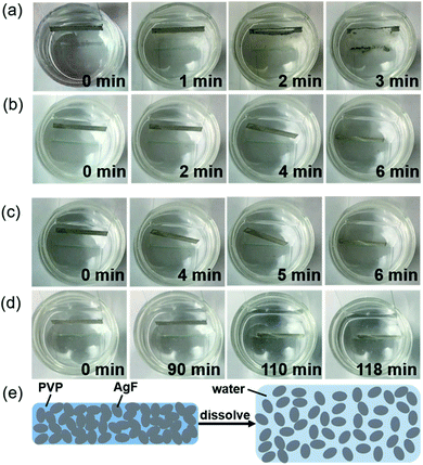
The transient behavior of the AgF/PVP composite tracks is examined as displayed in Fig. 5, which shows the sequential images of the dissolution of AgF/PVP tracks with different Ag contents. The AgF/PVP conductive tracks are disintegrated or slip into the water after several minutes or hours depending on the composition of the tracks. The AgF/PVP conductive track with 40% AgFs starts to dissolve after it is placed in water for 1 minute, and some of the AgFs slipped from the glass substrates. An obvious crack is generated in the AgF/PVP composite track followed by total disintegration in water after 3 minutes. It is concluded that rapid dissolution of the AgF/PVP conductive track occurs due to the addition of water-soluble PVP, which binds the AgFs together to form a highly conductive track and dissolves the AgF clusters after being placed in water (Fig. 5(e)). The excellent electrical performance and transience of the AgF/PVP composite tracks enable potential applications in transient electronics to solve the E-waste issue. When more AgFs are added, the AgF/PVP tracks also fail after several or a hundred minutes as shown in Fig. 5(b–d). The AgF/PVP tracks creep into the water without decomposition because the AgFs are closely piled up with higher AgF contents such that only the surface is uncovered and loose PVP is dissolved in water to destroy the connection of the composite tracks and glass substrates. Although AgFs/PVP composite tracks with higher AgF containment (45%, 50% and 60%) have better conductivity, the failure behavior could cause a short out or program disruption.
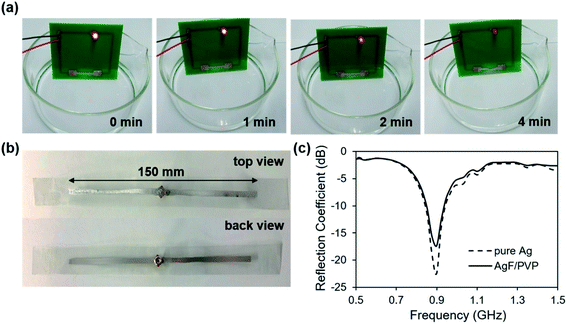
The AgF/PVP composite track has a great advantage compared with those previously reported, as shown in Table 1. The conductivity of the AgF/PVP composite track is better than that in other papers, except for the Mg trace, which is prepared by a complex physical deposition method. The dissolution duration of our AgF/PVP composite is shorter than those of other materials. Considering both the conductivity and transient property, the AgF/PVP composite track with 40% AgF content is suitable for application in transient circuits as demonstrated in our experiment (Fig. 6). The AgF/PVP conductive track is printed on a PCB to work as a component of the wire in the LED circuit, and it is immersed into water to view the variations in the brightness of the LED. The brightness of the LED gradually weakens with the dissolution of the AgF/PVP track and finally dies out after 4 minutes when the AgF/PVP track is broken. The application of the AgF/PVP conductive track as further demonstrated, showing that the AgF/PVP ink is printed on a PET substrate to fabricate a dipole antenna device as shown in Fig. 6(b). The resistance of each pole of the AgF/PVP antenna is 4 Ohm, which is relatively high compared with 0.5 Ohm resistance of the pure Ag antenna. The results show that the pure Ag dipole antenna return loss is −22 dB at the design frequency of 900 MHz. In contrast, the return loss of the AgF/PVP antenna at the same frequency is −17 dB, showing a performance similar to that of the pure Ag antenna due to the high conductivity. The excellent performance of the AgF/PVP transient antenna makes it potentially useful in information transmission and security.
| Materials | Resistance or conductance | Thickness | Dissolving duration | Ref. |
|---|---|---|---|---|
| a Ag NW represents silver nanowire. | ||||
| W strip | 5200 S m−1 | 40 μm | 8 minutes | 10 |
| Mg trace | 1.04 Ω mm−1 | 300 nm | 3 hours | 23 |
| Ag NW transparent electrode | 6 Ω sq−1 | 58% | 30 minutes | 9 |
| Ag microparticles trace | 1.59 Ω sq−1 | — | 500 seconds | 40 |
| AgF/PVP composite track | 8.9 mΩ cm | 83 μm | 180 seconds | Our work |
4 Conclusion
In summary, we have proposed a highly conductive and transient track from a composite material of AgFs and PVP which are prepared at 80 °C for 3 minutes. The AgF/PVP composite track with 40% AgF content has an excellent resistivity of 8.9 mOhm cm. Also, the AgF/PVP conductive tracks show an impressive transient performance, that the AgF/PVP tracks are dissolved in water within only 3 minutes. The applications of the transient AgF/PVP composite track in a LED circuit and dipole antenna demonstrate its potential in transient electronics. To achieve applications in implantable or wearable devices, the AgF/PVP conductive tracks will be printed on flexible substrates and encapsulated to avoid humility in the environment. We hope the work can promote the development of the transient electronic.Conflicts of interest
The authors declare that they have no conflict of interest.Acknowledgements
The authors are grateful for financial support from the National Natural Science Foundation of China (Grant No. 51705115). The authors declare that they have no conflict of interest.References
- B. H. Robinson, Sci. Total Environ., 2009, 408, 183–191 CrossRef CAS.
- L. H. Yamane, V. T. de Moraes, D. C. R. Espinosa and J. A. S. Tenório, Waste Manag., 2011, 31, 2553–2558 CrossRef CAS.
- K. K. Fu, Z. Wang, J. Dai, M. Carter and L. Hu, Chem. Mater., 2016, 28, 3527–3539 CrossRef CAS.
- R. Li, L. Wang, D. Kong and L. Yin, Bioact. Mater., 2018, 3, 322–333 CrossRef.
- H. Cheng, J. Mater. Res., 2016, 31, 2549–2570 CrossRef CAS.
- S.-W. Hwang, D.-H. Kim, H. Tao, T.-i. Kim, S. Kim, K. J. Yu, B. Panilaitis, J.-W. Jeong, J.-K. Song, F. G. Omenetto and J. A. Rogers, Adv. Funct. Mater., 2013, 23, 4087–4093 CrossRef CAS.
- R. Widmer, H. Oswald-Krapf, D. Sinha-Khetriwal, M. Schnellmann and H. Boni, Environ. Impact Assess. Rev., 2005, 25, 436–458 CrossRef.
- X. Tang, C. Shen, D. Shi, S. A. Cheema, M. I. Khan, C. Zhang and Y. Chen, J. Hazard. Mater., 2010, 173, 653–660 CrossRef CAS.
- Y. Chen, H. Lu, F. Xiu, T. Sun, Y. Ding, J. Liu and W. Huang, Sci. Rep., 2018, 8, 6408 CrossRef.
- X. Huang, Y. Liu, S.-W. Hwang, S.-K. Kang, D. Patnaik, J. F. Cortes and J. A. Rogers, Adv. Mater., 2014, 26, 7371–7377 CrossRef CAS.
- S. K. Kang, G. Park, K. Kim, S. W. Hwang, H. Cheng, J. Shin, S. Chung, M. Kim, L. Yin, J. C. Lee, K. M. Lee and J. A. Rogers, ACS Appl. Mater. Interfaces, 2015, 7, 9297–9305 CrossRef CAS.
- S. W. Hwang, S. K. Kang, X. Huang, M. A. Brenckle, F. G. Omenetto and J. A. Rogers, Adv. Mater., 2015, 27, 47–52 CrossRef CAS.
- S.-W. Hwang, G. Park, C. Edwards, E. A. Corbin, S.-K. Kang, H. Cheng, J.-K. Song, J.-H. Kim, S. Yu, J. Ng, J. E. Lee, J. Kim, C. Yee, B. Bhaduri, Y. Su, F. G. Omennetto, Y. Huang, R. Bashir, L. Goddard, G. Popescu, K.-M. Lee and J. A. Rogers, ACS Nano, 2014, 8, 5843–5851 CrossRef CAS.
- G. A. Salvatore, J. Sülzle, F. Dalla Valle, G. Cantarella, F. Robotti, P. Jokic, S. Knobelspies, A. Daus, L. Büthe, L. Petti, N. Kirchgessner, R. Hopf, M. Magno and G. Tröster, Adv. Funct. Mater., 2017, 27, 1702390 CrossRef.
- K. J. Yu, D. Kuzum, S. W. Hwang, B. H. Kim, H. Juul, N. H. Kim, S. M. Won, K. Chiang, M. Trumpis, A. G. Richardson, H. Cheng, H. Fang, M. Thomson, H. Bink, D. Talos, K. J. Seo, H. N. Lee, S. K. Kang, J. H. Kim, J. Y. Lee, Y. Huang, F. E. Jensen, M. A. Dichter, T. H. Lucas, J. Viventi, B. Litt and J. A. Rogers, Nat. Mater., 2016, 15, 782–791 CrossRef CAS.
- T. Lei, M. Guan, J. Liu, H. C. Lin, R. Pfattner, L. Shaw, A. F. McGuire, T. C. Huang, L. Shao, K. T. Cheng, J. B. Tok and Z. Bao, Proc. Natl. Acad. Sci. U. S. A., 2017, 114, 5107–5112 CrossRef CAS.
- L. Meng, S. M. Mahpeykar, Q. Xiong, B. Ahvazi and X. Wang, RSC Adv., 2016, 6, 85427–85433 RSC.
- Y. Yang, K. Xu, T. Vervust and J. Vanfleteren, Sens. Actuators, B, 2018, 261, 144–152 CrossRef CAS.
- Y. Yang, T. Vervust, S. Dunphy, S. Van Put, B. Vandecasteele, K. Dhaenens, L. Degrendele, L. Mader, L. De Vriese, T. Martens, M. Kaufmann, T. Sekitani and J. Vanfleteren, Adv. Electron. Mater., 2018, 4, 1800071 CrossRef.
- Y. Yang, G. Chiesura, T. Vervust, F. Bossuyt, G. Luyckx, J. Degrieck and J. Vanfleteren, Sens. Actuators, A, 2016, 243, 103–110 CrossRef CAS.
- A. Tuncuk, V. Stazi, A. Akcil, E. Y. Yazici and H. Deveci, Miner. Eng., 2012, 25, 28–37 CrossRef CAS.
- M. Goosey and R. Kellner, Circuit World, 2003, 29, 33–37 CrossRef CAS.
- S. W. Hwang, H. Tao, D. H. Kim, H. Cheng, J. K. Song, E. Rill, M. A. Brenckle, B. Panilaitis, S. M. Won, Y. S. Kim, Y. M. Song, K. J. Yu, A. Ameen, R. Li, Y. Su, M. Yang, D. L. Kaplan, M. R. Zakin, M. J. Slepian, Y. Huang, F. G. Omenetto and J. A. Rogers, Science, 2012, 337, 1640–1644 CrossRef CAS.
- L. Yin, H. Cheng, S. Mao, R. Haasch, Y. Liu, X. Xie, S.-W. Hwang, H. Jain, S.-K. Kang, Y. Su, R. Li, Y. Huang and J. A. Rogers, Adv. Funct. Mater., 2014, 24, 645–658 CrossRef CAS.
- D. R. Son, A. V. Raghu, K. R. Reddy and H. M. Jeong, J. Macromol. Sci., Part B: Phys., 2016, 55, 1099–1110 CrossRef CAS.
- K. R. Reddy, B. C. Sin, K. S. Ryu, J.-C. Kim, H. Chung and Y. Lee, Synth. Met., 2009, 159, 595–603 CrossRef CAS.
- K. R. Reddy, K. V. Karthik, S. B. B. Prasad, S. K. Soni, H. M. Jeong and A. V. Raghu, Polyhedron, 2016, 120, 169–174 CrossRef CAS.
- M. Hassan, K. R. Reddy, E. Haque, S. N. Faisal, S. Ghasemi, A. I. Minett and V. G. Gomes, Compos. Sci. Technol., 2014, 98, 1–8 CrossRef CAS.
- S. H. Choi, D. H. Kim, A. V. Raghu, K. R. Reddy, H.-I. Lee, K. S. Yoon, H. M. Jeong and B. K. Kim, J. Macromol. Sci., Part B: Phys., 2011, 51, 197–207 CrossRef.
- K. R. Reddy, K.-P. Lee and A. I. Gopalan, J. Appl. Polym. Sci., 2007, 106, 1181–1191 CrossRef CAS.
- K. R. Reddy, K.-P. Lee, Y. Lee and A. I. Gopalan, Mater. Lett., 2008, 62, 1815–1818 CrossRef CAS.
- K. R. Reddy, K. P. Lee and A. I. Gopalan, J. Nanosci. Nanotechnol., 2007, 7, 3117–3125 CrossRef CAS.
- H. M. H. Kakarla Raghava Reddy, Y. Lee and A. V. Raghu, J. Polym. Sci., Part A: Polym. Chem., 2010, 48, 1477–1484 CrossRef.
- Y. R. Lee, S. C. Kim, H.-i. Lee, H. M. Jeong, A. V. Raghu, K. R. Reddy and B. K. Kim, Macromol. Res., 2011, 19, 66–71 CrossRef CAS.
- M. U. Khan, K. R. Reddy, T. Snguanwongchai, E. Haque and V. G. Gomes, Colloid Polym. Sci., 2016, 294, 1599–1610 CrossRef CAS.
- S. J. Han, H.-I. Lee, H. M. Jeong, B. K. Kim, A. V. Raghu and K. R. Reddy, J. Macromol. Sci., Part B: Phys., 2014, 53, 1193–1204 CrossRef CAS.
- M. B. Gebeyehu, Y. H. Chang, A. K. Abay, S. Y. Chang, J. Y. Lee, C. M. Wu, T. C. Chiang and R. I. Murakami, RSC Adv., 2016, 6, 54162–54168 RSC.
- L. H. Tjeng, M. B. Meinders, J. van Elp, J. Ghijsen, G. A. Sawatzky and R. L. Johnson, Phys. Rev. B: Condens. Matter Mater. Phys., 1990, 41, 3190–3199 CrossRef CAS.
- J. F. Waver and G. B. Hoflund, Chem. Mater., 1994, 6, 1693–1699 CrossRef.
- R. Jamshidi, S. Çinar, Y. Chen, N. Hashemi and R. Montazami, J. Polym. Sci., Part B: Polym. Phys., 2015, 53, 1603–1610 CrossRef CAS.
Footnote |
| † Electronic supplementary information (ESI) available. See DOI: 10.1039/d0ra06603f |
| This journal is © The Royal Society of Chemistry 2020 |

