 Open Access Article
Preparation and application of sunlight absorbing ultra-black carbon aerogel/graphene oxide membrane for solar steam generation systems†
Mahsa Mohsenpoura,
Siamak Motahari *a,
Fariba Tajabadi*b and
Mohammad Najafia
aSchool of Chemical Engineering, College of Engineering, University of Tehran, Tehran, Iran. E-mail: smotahari@ut.ac.ir
bDepartment of Nanotechnology and Advanced Materials, Materials and Energy Research Center, Alborz, Iran. E-mail: f.tajabadi@merc.ac.ir
First published on 17th November 2020
Abstract
In this study, sunlight absorbing membranes consisting of ultra-black resorcinol–formaldehyde (RF)-based carbon aerogel (CA) and hydrophilic graphene oxide (GO) suspension were fabricated. To investigate the effect of substrate structure, CA/GO ink was cast onto two different layers including 3D modified copper foam (MCF) and 2D paper sheet. The copper foam (CF) was treated with a new and simple modification method to enhance the hydrophilicity. Finally, the solar steam generation performances of the prepared membranes were evaluated. The optical analyses indicated that 2D and 3D samples respectively reflected ∼4.5% and ∼10%, and transmitted ∼0% of the incident light. The water contact angle measurements revealed a significant change in the wettability of the CF layer representing a contact angle of 139.41° before the modification. Based on the water evaporation rates, the efficiencies of 81.1% and 91.4% (at 1 kW m−2) were achieved for 2D and 3D absorbents, respectively. In addition to eliminating the geometrical restrictions of the monolithic absorbents, the results verified that CA/GO ink-based absorbents were promising materials for solar steam generation systems (SSG) due to the high light absorption, superhydrophilicity and porous structure.
Introduction
Carbon aerogels (CA) are a group of open cell porous 3D materials with high specific surface area, low density and low thermal conductivity. The nanostructure of CA is influenced by many factors, such as the precursors and preparation process conditions. Cellulose, carbon nanotubes (CNTs), graphene oxide (GO), and resorcinol–formaldehyde (RF) aerogel can be used as CA precursors.1,2RF aerogel is the first synthesized organic aerogel with the polycondensation of resorcinol and formaldehyde in the presence of basic or acidic catalysts. This aerogel converted to carbonaceous 3D network using pyrolysis process. In comparison to other precursors of CA (including CNT and GO), RF aerogel possesses the cost effective raw materials and preparation process, has the facile synthesis procedure, and can be obtained by ambient pressure drying. Cellulose, GO and CNT aerogels required expensive drying methods (freeze-drying and/or supercritical drying) to prevent the collapse of 3D network. Due to special features, CA has a wide application in catalysis, sorption, membrane, coating, radiation detection, acoustic and thermal insulation, energy storage devices and photothermal application.1–3
Solar energy, the most abundant green inexhaustible renewable energy source on the Earth,4,5 is widely used in many fields including solar photovoltaics, solar architecture, production of hydrogen, photocatalysis, artificial photosynthesis.6,7 In addition to the above mentioned applications, utilization of photothermal materials for solar steam generation (SSG) has recently received much attention because of the high solar-to-vapor conversion efficiency which is prominent in extensive applications such as power generation, seawater desalination and purification, wastewater treatment, liquid–liquid phase separation, and sterilization.5,6,8
An ideal SSG system comprises of three main components: light absorbent layer to absorb the solar spectrum, water supplier layer to transport water from bulk to the surface due to the capillary effect, and thermal insulator layer to minimize the heat loss to the bulk water. In comparison to the traditional solar desalination water, these systems showed improved solar energy conversion efficiency due to the localization of heat in a thin layer and decreasing the heat loss.5,6,8–11
Various photothermal materials including metallic nanoparticles,12,13 metal-salts/oxides, carbon materials,5–8,10,11,14–22 ceramic, composite materials,23 organic polymers,4,9,24,25 covalent organic frameworks,26 semiconductor materials27 and wood-based materials28 have been investigated.6,11 Plasmonic and carbon-based materials are the most common materials used in SSG systems. However, due to the excellent light absorption, corrosion resistance and availability, a lot of research has focused on different carbon-based materials10,29 such as self-floating photothermal membranes.30
Among different types of carbon materials, CA has been taken into consideration due to the special features making this material a good choice for SSG systems. The aerogel porosity decreases light reflection and increases light scattering inside pores which improves light absorption. Also, the interconnected pores provide channels for fast water supply and vapor exit.31,32
Graphene- and GO-based aerogels are the promising photothermal materials for efficient SSG systems.6,7 Jiang et al.33 synthesized bilayer hybrid composed of bacterial nanocellulose (BNC) and reduced graphene oxide (RGO) with incorporation of GO flakes in BNC fibers. Using this absorbent, the evaporation rate of 11.8 kg m−2 h−1 under solar illumination of 10 kW m−2 was achieved which was about 13 times higher, in comparison to the evaporation rate in the absence of the bilayer hybrid. Hu et al.34 prepared a free floating GO-based aerogel using GO sheets, CNT and sodium alginate. The efficiency of about 83% under 1 sun illumination was obtained. Fu et al.35 used GO to produce graphene aerogel and investigated its application in SSG device. The results indicated that the absorbent possessed 53.6% and 82.7% solar evaporation efficiencies at 1 and 10 sun illuminations, respectively. Jiang et al.36 designed bilayer aerogel consisted of cellulose nanofiber and CNT. The fabricated aerogel showed the efficiency of 76.3% and 81.4% under 1 and 3 sun illuminations, respectively. Zhang et al.37 developed the SSG system based on highly vertically ordered pillar array of graphene-assembled framework (HOPGF). The high water evaporation rate of 2.10 kg m−2 h−1 was achieved under 1 kW m−2.
However, graphene, GO, CNT and cellulose aerogel-based SSG systems showed good evaporation efficiencies, they required expensive drying methods and precursors, as mentioned. Therefore, facile preparation of the cost effective CA-based absorbent for SSG is still remains a challenge.6,7 As explained, RF-based CA is a good choice to be used instead of graphene and GO aerogels in SSG system. Although monolithic aerogels have been commonly used in SSG systems, the ink is easier to prepare and use than the monolithic structure. Moreover, ink-based sunlight absorbing membrane can eliminate the geometrical restrictions and defects of the monolithic aerogel-based absorbents. On the other hand, the membrane surface wettability is the key factor determining the water transfer rate and therefore evaporation rate and efficiency. As reported,38 slow water delivery from the hydrophobic layer limited the evaporation flux. However, fast water transportation from the hydrophilic membrane enhanced the evaporation rate. Therefore, it is essential to fabricate a hydrophilic sunlight absorbing membrane.
In the present study, facile fabrication of an ideal sunlight absorbing membranes with high light absorption, excellent hydrophilicity and appropriate porosity for SSG systems was investigated. To reach this goal, ultra-black RF-based CA powder was mixed with hydrophilic GO suspension to obtain an ink with the properties of CA and GO. The ink was easily cast onto two substrates with different morphologies: 3D porous copper foam and 2D dense paper. To enhance the hydrophilicity of copper foam, in order to absorb water and transfer it to black sunlight absorbing surface, it was modified using a new method prior to ink casting. The performance of the membranes was investigated as absorbents in SSG system, for the first time. The influences of porosity, morphology, light absorption properties, hydrophilicity and temperature localization on the water evaporation rate and efficiency were studied using different techniques, and the membrane with the highest efficiency was selected as a promising absorbent for SSG system.
Experimental
Materials
Resorcinol (DAUJUNG, Korea), formalin (35%, Ghatran shimi, Iran), sodium bicarbonate (DAUJUNG, Korea), deionized water (DI), ethanol (99%), graphene oxide dispersion in water (2 mg ml−1, Sharif Solar, Iran), microcrystalline cellulose (Merck, Germany), sodium hydroxide (Ghatran shimi, Iran), urea (Ghatran shimi, Iran), copper foam (99%, Singapore) and paper (Hybrite A4-80 GSM, Indonesia) were purchased and used as received.Fabrication of membranes
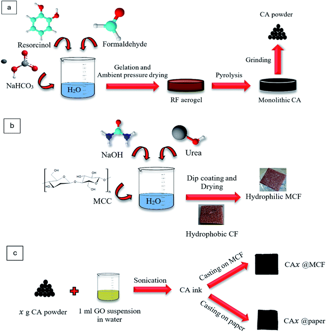 | ||
| Fig. 1 Schematics of (a) CA powder preparation, (b) CF modification, and (c) absorbents fabrication. | ||
To obtain CA, the prepared aerogel, was pyrolyzed using tubular furnace, in Ar atmosphere at 800 °C. The resulted monolithic CA was ball milled for 2 h at 200 rpm, and finally CA powder was achieved (Fig. 1a).
After the immersion of CF in ethanol, it was washed several times with water. Finally, it was dried at ambient temperature and the modified CF (MCF) was obtained. It was a promising and facile method to prepare the hydrophilic CF. The hydrophilic oxygen-containing materials facilitate the water transfer30 in membrane which is a key factor in SSG systems.
To fabricate the absorbents, 1.5 ml (for MCF substrate) and 0.5 ml (for paper substrate) of the CA ink were directly cast onto the substrates with the area of 25 × 25 mm2. Then they were dried naturally (Fig. 1c).
The membranes were named as CA1@MCF, CA3@MCF, CA5@MCF, CA1@paper, CA3@paper and CA5@paper, where “1”, “3” and “5” refer to 0.01, 0.03 and 0.05 g of CA in the ink, respectively, and “MCF” and “paper” determine the employed substrates. As mentioned, MCF has a 3D porous structure, and paper has a 2D flat structure.
Characterization
The chemical bonds and functional groups of RF aerogel and CA were studied using Fourier Transform Infrared Spectroscopy (FTIR, PerkinElmer, Germany). The spectra were recorded in the range of 4000 cm−1 to 450 cm−1. The aerogels were dried prior to the test.X-Ray Diffraction Spectroscopy (XRD) analysis was used (Bruker AXS, D8-Advance, Germany) to investigate the structure of the synthesized CA. Interlayer spacing (d002), the crystallite size (La) and crystallite height (Lc) were calculated using Bragg (eqn (1)) and Scherrer (eqn (2)) equations, respectively.
d002 = λ(2sin![[thin space (1/6-em)]](https://www.rsc.org/images/entities/char_2009.gif) θ)−1 θ)−1
| (1) |
L = kλ(β![[thin space (1/6-em)]](https://www.rsc.org/images/entities/char_2009.gif) cos cos![[thin space (1/6-em)]](https://www.rsc.org/images/entities/char_2009.gif) θ)−1, θ)−1,
| (2) |
To evaluate the specific surface area and pore size distribution, Bruner–Emmett–Teller (BET) and Barret–Joyner–Halenda (BJH) methods were employed.
Using Field Emission Scanning Electron Microscopy (FESEM, Mira 3-XMU) the morphological structure of the CA powder, CF, MCF and paper substrates and the samples were observed. Energy Dispersive X-ray Spectroscopy (EDS) was used to determine the elemental composition and investigate the elemental mapping.
Diffuse Reflection Spectroscopy (DRS) and Diffuse Transmittance Spectroscopy (DTS) analyses were performed using Avantes spectrophotometer (AvaSpec 2018 TEC, Netherlands) to examine the reflectance and transmittance properties of the absorbents prepared with different CA ink concentrations. In order to measure transmittance, the sample was placed at the light input (entrance of integrating sphere) and the transmitted light was collected and measured by detector. To evaluate the reflectance, the membrane was put at the output of the integrating sphere and the reflected light was measured using the detector.
To specify water hydrophilicity of absorbents and substrates, Water Contact Angle was measured according to ASTM D7334 using a contact angle meter apparatus (JIKAN CAG-20, Iran). For CF sample, a droplet (4 μl) was placed on the surface and the image was recorded in a short time (about a second) after placing the droplet. The contact angle was determined using the image. For each membrane, the measurements was repeated 2 or 3 times. The video of measurements for two membranes were provided in ESI.†
To measure the water mass loss, a tissue (as water supplier), a sponge (as thermal insulator) and the fabricated absorbents were used, as reported.38 The amount of the evaporated water per 35 min was measured in different conditions: under one sun illumination (Sharif Solar, Iran), and at ambient condition (at 13 pm, in September, (35.747628, 50.957921)). Some experiments were repeated several times.
Infrared thermogram camera (Olip-P200, England) was used to observe the temperature gradient within the illumination.
Results and discussion
Characterization of RF and CA
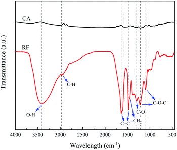
The functional groups and chemical bonds of RF aerogel and corresponding CA were studied using FTIR analysis, as represented in Fig. 2. In RF aerogel spectrum, the peak at 3400 cm−1 is ascribed to O–H groups bonded to the aromatic ring. C–H stretching peaks are located at 2973 cm−1 and 2939 cm−1. The observed peaks at 1638 cm−1 and 1475 cm−1 are attributed to C![[double bond, length as m-dash]](https://www.rsc.org/images/entities/char_e001.gif) C vibration. –CH2 bending vibration peak (about 1465 cm−1) overlapped with the peak at 1475 cm−1. The appeared peaks at 1219 cm−1 and 1098 cm−1 correspond to C–O–C linkage stretching.44,45 The peak at 1296 cm−1 is assigned to C–O.
C vibration. –CH2 bending vibration peak (about 1465 cm−1) overlapped with the peak at 1475 cm−1. The appeared peaks at 1219 cm−1 and 1098 cm−1 correspond to C–O–C linkage stretching.44,45 The peak at 1296 cm−1 is assigned to C–O.
After the carbonization, the peaks such as O–H, C–H, C![[double bond, length as m-dash]](https://www.rsc.org/images/entities/char_e001.gif) C become significantly weaker and even some peaks disappear, as displayed in FTIR spectrum of CA. The removal of oxygen and hydrogen groups due to the carbonization process at 800 °C, and the transformation of RF aerogel to pure carbon result in a great reduction of peak intensities.46–49
C become significantly weaker and even some peaks disappear, as displayed in FTIR spectrum of CA. The removal of oxygen and hydrogen groups due to the carbonization process at 800 °C, and the transformation of RF aerogel to pure carbon result in a great reduction of peak intensities.46–49
For further investigation, EDS elemental analysis of RF and CA and EDS mapping for CA powder was performed (Fig. S1†). The results indicates that RF and CA contain C and O elements. The weight percentages of C in RF and CA are 54.6 wt% and 87.5 wt%, respectively. As expected, the content of C in CA is higher than that of in RF. The presence of O in CA could be due to the moisture or slight oxidation of CA in the pyrolysis step.
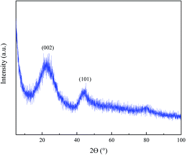
In order to study the crystalline structure of the prepared CA, XRD analysis was performed. As illustrated in Fig. 3, CA shows broad diffraction peaks at 2θ = 22.88° and 44.52° for (002) and (101) planes of graphite, respectively. The broad peaks shifting towards a smaller scattering angle (in comparison to graphite) indicates the disordered and turbostratic carbon. Using XRD spectrum and eqn (1) and eqn (2), d002 was obtained to be 0.387 nm. Also La and Lc were respectively equal to 1.63 nm and 0.79 nm representing the formation of nano sized graphitic structure.42,43
Porous texture assessment
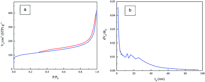
Textural properties of the CA was evaluated with N2 adsorption–desorption isotherm. As depicted in Fig. 4a, the adsorption–desorption isotherm displays type-IV IUPAC and the type-H3 hysteresis with the out-of-level N2 adsorption at high relative pressure which indicates the capillary condensation in mesoporous structures and the plate-like particles which form slit-shaped pores. It was found that the specific surface area (SBET) of CA powder was 398 m2 g−1. Also, the total pore volume of the CA was 0.615 cm3 g−1.The pore size distribution of CA was studied by BJH method as illustrated in Fig. 4b. As shown, a broad pore size distribution (1 nm to 90 nm) from micro to meso pore size is observed. Main pore sizes are found to be in the range of 10 nm to 30 nm, which are indicative of mesopores.50,51 This porous texture is necessary for efficient SSG system and makes the CA a suitable absorbent material to be used in these systems.
Morphological study
SEM micrographs of CA powder (after ball milling), CF before and after modification (MCF), paper and prepared absorbents with paper and MCF substrates are shown in Fig. 5. As illustrated in Fig. 5a and S2a,† CA powder consists of interconnected 3D network with nano sized particles and pores and non-uniform textural porosity.52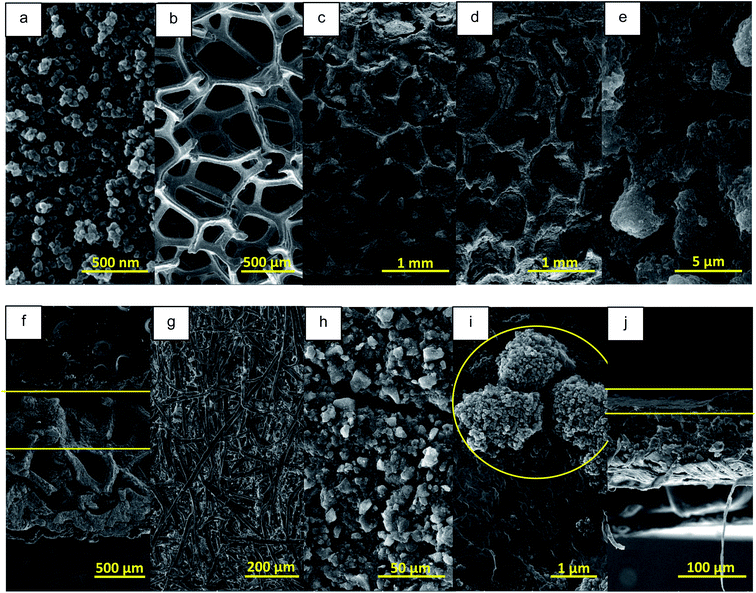 | ||
| Fig. 5 SEM micrographs of (a) CA powder, (b) CF, (c) MCF, (d and e) CA3@MCF, (f) cross section of CA3@MCF, (g) paper sheet, (h and i) CA3@paper and (j) cross section of CA3@paper membrane. | ||
As observed, ball milling has not destroyed the aerogel structure.
In Fig. 5b and S2b,† the micron sized unmodified CF fibrous network with the pore diameter of ∼600 μm is observed. To obtain hydrophilic CF, it was dipped into MCC solution, followed by drying. As shown in Fig. 5c, S2c† and 6, CF pores were filled with cellulose and CF skeleton was wrapped by MCC fibers which significantly improved the hydrophilicity. Therefore, to obtain CA coated CF, MCF was employed as the substrate instead of CF. CA ink was absorbed by MCC fibers and almost filled the MCF pores which led to higher hydrophilicity (Fig. 5d and S2d†).
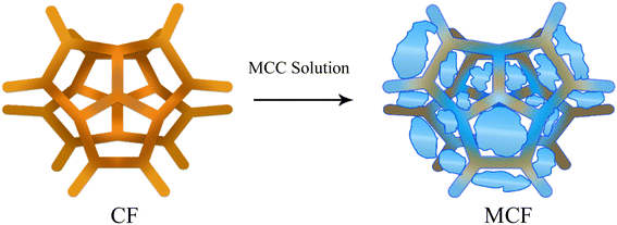 | ||
| Fig. 6 The diffusion of MCC into CF structure leading to the significant increase in hydrophilicity. | ||
In higher magnification (Fig. 5e), the GO sheets and CA particles are clearly observed. The cross-section micrograph shows the diffusion of CA ink in MCF porous structure (Fig. 5f). These porous structures with nano sized (CA) and micron sized (MCF) pores are appropriate to water absorption and vapor escape in SSG systems.
Paper has 2D entangled micron sized fibrous structure with low porosity compared to CF and MCF (Fig. 5g). In CA3@paper membrane, CA ink completely covers the paper substrate (Fig. 5h). Also, in higher magnification (Fig. 5i and S2e†), GO sheets and CA are seen. According to the cross-section micrograph (Fig. 5j), the CA ink is located on the paper substrate.
For CA3@MCF and CA3@paper, the results of EDS elemental analysis and EDS mapping images were provided in Fig. S3.† As illustrated, in case of CA3@paper, C and O are uniformly distributed all over the sample, and as expected, the content of O is very low in comparison to C. In this membrane, the substrate is completely covered by CA/GO. However, CA3@MCF exhibits the non-uniform elemental distribution, compared to CA3@paper. In CA-filled parts, the content of C is higher than that of O and Cu elements and on MCF fibers, the content of O is the highest, due to the presence of cellulose.
Light absorption examination
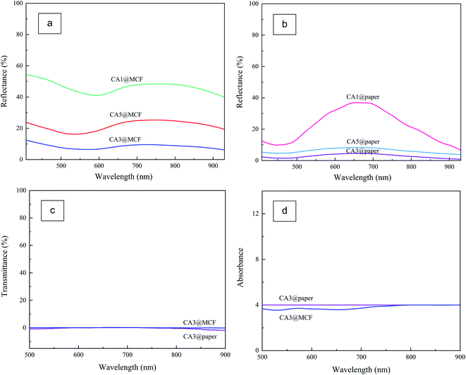
To determine the optical properties of absorbents and select the efficient CA ink, DRS and DTS analyses were performed. The reflectance spectra of the CA coated MCF and paper substrates in the visible and near infrared regions are illustrated in Fig. 7a and b. As displayed, generally, the samples with MCF substrate (Fig. 7a) possess higher reflectance compared to the counterpart samples on paper substrate (Fig. 7b). With increase in CA content from 0.01 g to 0.03 g, the reflectance descends, as expected. However, with further increase of CA content from 0.03 g to 0.05 g, the reflectance shows a little increment. As the concentration increases (0.05 g ml−1), the concentrated CA ink causes the paper substrate to shrink, and also causes both substrates surface (MCF and paper) to crack after drying, unlike the concentration of 0.01 and 0.03 g ml−1. Therefore, the CA3 was chosen as the efficient ink and it was used for further experiments. Based on the data, the reflectances of CA3@MCF and CA3@paper are about 10% and 4.5%, respectively.As illustrated in Fig. 7c, CA3@MCF and CA3@paper samples display very low transmittances (approximately zero) and absorb almost all incident light. However, the absorbance of CA3@paper is slightly higher than CA3@MCF (Fig. 7d). The good optical feature is due to the optical absorption of CA particles. The ultra-black CA with porous network blocks the reflectance, increases the light path length, and reduces transmittance. Using CA, both the transmittance and reflectance are minimized to obtain broadband light absorbent layer, which is essential for efficient SSG system.33,36,53
Hydrophilicity measurements
The water contact angle measurements was used to assess the hydrophilicity of CF, MCF and paper substrates, and absorbents, as depicted in Fig. 8. The water contact angle of CF is 139.41° showing remarkable hydrophobic properties. Despite the porous structure of CF, the water droplet is not absorbed by CF, due to the high hydrophobicity (Fig. 8a). However, after the modification of CF (MCF), the water droplet is absorbed by the sample in about 0.1 s, due to the superhydrophilic porous structure, as shown in Fig. 8b and Video S1.† The significant change in CF hydrophilicity caused by the employed new treatment method resulting in the presence of MCC in CF framework, as illustrated in Fig. 5c and 6. The same phenomenon is observed for CA3@MCF membrane caused by the presence of both MCF and hydrophilic CA ink due to the existence of GO (Fig. 8c and Video S2†).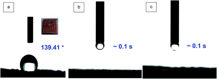 | ||
| Fig. 8 The water contact angle of (a) hydrophobic CF, (b) MCF substrate, (c) CA3@MCF membrane (the videos and figures of the water droplet absorption by MCF (Video S1†), CA3@MCF (Video S2†), paper (Fig. S4a†) and CA3@paper (Fig. S4b†) samples are available in ESI†). | ||
In case of paper (Fig. S4a†), the droplet is formed and absorbed over time (∼1 min), however, for CA3@paper sample (Fig. S4b†), the droplet is absorbed in shorter time (5 s) indicating the influence of CA ink (as the top layer) on the hydrophilicity.
The comparison of CA3@MCF and CA3@paper reveals that the presence of MCF substrate has stronger effect on the improvement of the absorbent hydrophilicity, against CA ink. Based on the data, absorbents possess very high hydrophilicity which is necessary for water supplying in SSG systems.6,34,54
Temperature variations
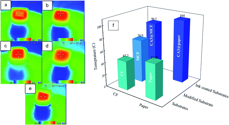
The infrared images of the dry absorbents and substrates after 2 min illumination are displayed in Fig. 9a–e, and the results are depicted in Fig. 9f. As seen, generally, the temperature of CA coated membranes are the highest due to the presence of CA with high light absorption. The temperature of paper substrate (57.9 °C) is higher than unmodified CF (47.7 °C). According to SEM micrographs (Fig. 5b and g), it could be ascribed to the 2D dense structure of paper compared to 3D porous CF. Likewise, the temperature of CA3@paper (104 °C) is higher than CA3@MCF (90.5 °C). Also, according to DRS and DTS results (Fig. 7), the absorbance and reflectance of CA3@paper was respectively higher and lower than CA3@MCF leading to the higher surface temperature under illumination. The significant increase of temperature in a short time makes the absorbents good candidates for SSG systems.The MCF substrate has higher temperature over unmodified one (CF) due to the structural changes after the CF immersion in MCC solution causing the presence of cellulose in MCF pores, as confirmed with SEM micrographs (Fig. 5b and c) and displayed in Fig. 6.
Water evaporation evaluation
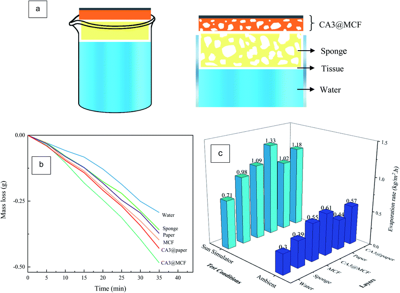
The SSG performance of the pure water (with no absorbent), sponge, 3D layers and 2D flat layers were evaluated using sun simulator (1 kW m−2) and at ambient condition. As illustrated in Fig. 10a, in the used configuration,38 due to the capillary effect, water is transferred through a tissue from the bulk water to the substrate and then CA layer. The sponge causes the reduction of heat loss to the bulk water.55,56Fig. 10b and c respectively show the water losses and evaporation rates for water without absorbent and with different layers. The water evaporation rates were calculated using water mass loss per 35 min, and per the area of absorbent membranes (25 × 25 mm2).
According to Fig. 10b and c, the water mass losses and consequently evaporation rates of pure water are found to be the minimum under simulated sunlight (1 kW m−2) and at ambient. Using the tissue and sponge, the evaporation rates ascend due to the enhancement of water supplying, caused by hydrophilic tissue, and decrease of heat loss to the water body, because of the barrier effect of sponge.36
Based on the data, in all test conditions, both substrates raise the water evaporation compared to water and sponge. The presence of 3D porous superhydrophilic MCF leads to the increase of water supplying and the evaporation rate is further enhanced. In the case of paper substrate, the evaporation rate is increased (versus water and sponge), however not as much as MCF, due to the 2D flat structure and slow water supplying.
In first 5 min, CA3@paper and paper respectively show higher mass loss in comparison to CA3@MCF and MCF layers ascribing to the higher light absorption (lower transmittance and reflectance) of paper substrate compared to MCF (Fig. 7). Over time, the mass loss of samples with MCF substrates is enhanced due to the significant hydrophilicity and water supplying of MCF membrane against paper, as discussed in contact angle measurement section (Fig. 8 and S4†).
With introducing the CA layer, in both cases (MCF and paper) and in both test conditions, the evaporation rates are enhanced due to the 3D hydrophilic porous structure in order to absorb the water and transfer the vapor, and high optical absorption of ultra-black CA (caused by the multiple scattering of incident light in nanostructure).33 The evaporation rate is increased about 1.9 times (under sun simulator), in comparison to the pure water with no absorbent layer.
However, CA3@paper sample shows higher light absorption (Fig. 7) and higher surface temperature (Fig. 9), CA3@MCF possesses the highest evaporation rate, in all conditions. This phenomenon is attributed to the 3D porous superhydrophilic structure and fast water supplying of MCF leading to the higher evaporation rate, but lower surface temperature, compared to 2D dense paper sheet. Based on the data, water supplying is the key factor which determines the evaporation rate.38,55 The results indicate that CA3@MCF is a promising photothermal material for SSG systems.
Generally, the evaporation rates under the sun simulator were higher due to the higher power density of sun simulator against the ambient condition.
In order to compare the results, the evaporation efficiency (η) was calculated using the eqn (3) and Fig. 10c:
 | (3) |
 is the evaporation rate per surface area of absorbent, hLV is the enthalpy change of water during the evaporation which includes both the liquid–vapor phase change enthalpy and sensible heat, and Pin is the power density of solar illumination.34,36,38,57
As depicted in Fig. 11a, water (without absorbent) and then sponge show the lowest efficiencies (48.9% and 67.8, respectively), and CA3@MCF and CA3@paper exhibit the highest efficiencies (91.4% and 81.1%, respectively) among all. As expected, due to the presence of ultra-black and superhydrophilic CA/GO layer, CA3@MCF and CA3@paper possess higher efficiency in comparison to their corresponding substrates (75.1% and 70.4%, respectively).
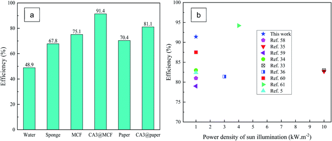 | ||
| Fig. 11 (a) The efficiency of water (without absorbent), sponge, substrates and absorbent layers, (b) comparison of the efficiency in literatures to this work. | ||
Fig. 11b displays the efficiency of aerogel- and porous carbon-based absorbents reported in literatures,5,33–36,58–61 and this work. In comparison to the other absorbents, higher efficiency was achieved in this work due to the employment of ultra-black nanoporous CA, superhydrophilic GO, and superhydrophilic modified substrate (MCF) with micron sized pores. However, the increased efficiency has been reported at higher power density (4 kW m−2).61 In previous studies, monolithic aerogels (including GO aerogel, cellulose aerogel, CNT aerogel) were used, however, in this work, CA ink was utilized resulting in the improved efficiency and removal of the geometrical constraints of monolithic aerogel-based absorbents versus the ink-based absorbent membranes.
Conclusions
In this study, the ink consisting of ultra-black RF-based CA and hydrophilic GO was prepared and cast onto two different structures including 3D porous CF and 2D paper sheet, as substrates. Due to the high hydrophobicity of CF, the new and easy modification method was performed to obtain superhydrophilic MCF. The performances of the fabricated ultra-black and superhydrophilic light absorbing membranes were investigated in SSG system.According to the water evaporation results, in the presence of CA3@MCF, the evaporation rate ascended about 1.9 times (compared to pure water). Despite that CA coated paper had higher light absorption and surface temperature, CA coated MCF showed the highest evaporation rate due to the 3D porous superhydrophilic MCF substrate leading to fast water supplying and higher evaporation rate against 2D flat paper substrate. This phenomenon confirmed that the porosity plays a major role in SSG systems. The high efficiencies of 91.4% and 81.1% (at 1 kW m−2) were achieved for CA3@MCF and CA3@paper, respectively.
According to the results, the prepared ink-based absorbent membranes consisting of ultra-black CA, GO and modified substrates, with high light absorption, high surface temperature under illumination, high hydrophilicity and porous structure (CA with nano sized pores and MCF containing micron sized pores), in order to enable water supplying and vapor channels, are promising absorbents for SSG systems. Moreover, CA ink-based sunlight absorbing membranes omit the limitations of monolithic aerogel-based absorbents in SSG system.
Conflicts of interest
There are no conflicts to declare.References
- S. Araby, A. Qiu, R. Wang, Z. Zhao, C. Wang and J. Ma, J. Mater. Sci., 2016, 51, 9157–9189 CrossRef CAS.
- M. Antonietti, N. Fechler and T. Fellinger, Chem. Mater., 2014, 26, 196–210 CrossRef CAS.
- S. Mulik, C. Sotiriou-leventis and N. Leventis, Chem. Mater., 2007, 19, 6138–6144 CrossRef CAS.
- X. Wang, Q. Liu, S. Wu, B. Xu and H. Xu, Adv. Mater., 2019, 31, 1807716 CrossRef.
- P. Mu, W. Bai, Y. Fan, Z. Zhang, H. Sun, Z. Zhu, W. Liang and A. Li, J. Mater. Chem. A, 2019, 7, 9673–9679 RSC.
- B. Huo, D. Jiang, X. Cao, H. Liang, Z. Liu, C. Li and J. Liu, Carbon, 2019, 142, 13–19 CrossRef CAS.
- X. Feng, J. Zhao, D. Sun, L. Shanmugam, J.-K. Kim and J. Yanga, J. Mater. Chem. A, 2019, 7, 4400–4407 RSC.
- J. Jia, W. Liang, H. Sun, Z. Zhu, C. Wang and A. Li, Chem. Eng. J., 2019, 361, 999–1006 CrossRef CAS.
- C. Li, D. Jiang, B. Huo, M. Ding and C. Huang, Nano Energy, 2019, 60, 841–849 CrossRef CAS.
- Z. Li, C. Wang, T. Lei, H. Ma, J. Su, S. Ling and W. Wang, Adv. Sustainable Syst., 2019, 3, 1800144 CrossRef.
- Y. Lin, W. Zhou and Y. Di, AIP Adv., 2019, 9, 055110–055116 CrossRef.
- Y. Yuan, C. Dong, J. Gu, Q. Liu, J. Xu, C. Zhou, G. Song, W. Chen, L. Yao and D. Zhang, Adv. Mater., 2020, 1907975–1907982 CrossRef CAS.
- A. Guo, Y. Fu, G. Wang and X. Wang, RSC Adv., 2017, 7, 4815–4824 RSC.
- H.-C. Yang, Z. Chen, Y. Xie, J. Wang, J. W. Elam, W. Li and S. B. Darling, Adv. Mater. Interfaces, 2019, 6, 1801252–1801258 CrossRef.
- Y. Zhang, S. K. Ravi and S. C. Tan, Adv. Sustainable Syst., 2019, 3, 1900044–1900050 CrossRef CAS.
- L. Sun, J. Liu, Y. Zhao, J. Xu and Y. Li, Carbon, 2019, 145, 352–358 CrossRef CAS.
- M. Zhu, J. Yu, C. Ma, C. Zhang, D. Wu and H. Zhu, Sol. Energy Mater. Sol. Cells, 2019, 191, 83–90 CrossRef CAS.
- S. Liu, C. Huang, X. Luo and C. Guo, Appl. Energy, 2019, 239, 504–513 CrossRef.
- X. Li, G. Xu, G. Peng, N. Yang, W. Yu and C. Deng, Appl. Therm. Eng., 2019, 161, 114195 CrossRef CAS.
- D. D. Xia and J. Liao, Nano Energy, 2019, 58, 322–330 CrossRef.
- Y. Chen, Y. Shi, H. Kou, D. Liu, Y. Huang, Z. Chen and B. Zhang, ACS Sustainable Chem. Eng., 2019, 7, 2911–2915 CrossRef CAS.
- P. Qiua, F. Liua, C. Xub, H. Chenc, F. Jiangc, Y. Lia and Z. Guo, J. Mater. Chem. A, 2019, 7, 13036–13042 RSC.
- G. Chen, N. Zhang, N. Li, L. Yu and X. Xu, Adv. Mater. Interfaces, 2019, 6, 1901715–1901724 Search PubMed.
- X. Han, L. Zang, S. Zhang, T. Dou, L. Li, J. Yang, L. Sun, Y. Zhangb and C. Wang, RSC Adv., 2020, 10, 2507–2512 RSC.
- F. Liu, L. Wang, R. Bradley, B. Zhao and W. Wu, RSC Adv., 2019, 9, 29414–29423 RSC.
- Z.-J. Xia, H.-C. Yang, Z. Chen, R. Z. Waldman, Y. Zhao, C. Zhang, S. N. Patel and S. B. Darling, Adv. Mater. Interfaces, 2019, 6, 1900254–1900259 CrossRef.
- F. Yu, X. Ming, Y. Xu, Z. Chen, D. Meng, H. Cheng, Z. Shi, P. Shen and X. Wang, Adv. Mater. Interfaces, 2019, 6, 1901168 CrossRef CAS.
- H. Gao, M. Yang, B. Dang, X. Luo, S. Liu, S. Li, Z. Chen and J. Li, Wood-based, RSC Adv., 2020, 10, 1152 RSC.
- Q. Zhang, W. Xu and X. Wang, Sci. China Mater., 2018, 61, 905–914 CrossRef CAS.
- Z. Li, W. Ma, J. Xu, M. Qian, H. Bi, W. Zhao, Z. Lv and F. Huang, Carbon, 2020, 170, 256–263 CrossRef CAS.
- Y. Lin, H. Xu, X. Shan, Y. Di, A. Zhao, Y. Hu and Z. Gan, J. Mater. Chem. A, 2019, 7, 19203–19227 RSC.
- X. Hu and J. Zhu, Adv. Funct. Mater., 2019, 30, 1907234–1907250 CrossRef.
- Q. Jiang, L. Tian, K. Liu, S. Tadepalli, R. Raliya, P. Biswas, R. R. Naik and S. Singamaneni, Adv. Mater., 2016, 28, 9400–9407 CrossRef CAS.
- X. Hu, W. Xu, L. Zhou, Y. Tan, Y. Wang, S. Zhu and J. Zhu, Adv. Mater., 2017, 29, 1604031–1604035 CrossRef.
- Y. Fu, G. Wang, T. Mei, J. Li, J. Wang and X. Wang, ACS Sustainable Chem. Eng., 2017, 5, 4665–4671 CrossRef CAS.
- F. Jiang, H. Liu, Y. Li, Y. Kuang, X. Xu, C. Chen, H. Huang, C. Jia, X. Zhao, E. Hitz, Y. Zhou, R. Yang, L. Cui and L. Hu, ACS Appl. Mater. Interfaces, 2018, 10, 1104–1112 CrossRef CAS.
- P. Zhang, Q. Liao, H. Yao, H. Cheng, Y. Huang, C. Yang, L. Jiang and L. Qu, J. Mater. Chem. A, 2018, 6, 15303–15309 RSC.
- C. Chang, P. Tao, B. Fu, J. Xu, C. Song, J. Wu, W. Shang and T. Deng, ACS Omega, 2019, 4, 3546–3555 CrossRef CAS.
- M. Aghabararpour, M. Mohsenpour, S. Motahari and A. Abolghasemi, J. Non-Cryst. Solids, 2018, 481, 548–555 CrossRef CAS.
- M. Aghabararpour, M. Mohsenpour and S. Motahari, Mater. Res. Express, 2019, 6, 075059 CrossRef CAS.
- M. Aghabararpour, M. Mohsenpour and S. Motahari, J. Appl. Polym. Sci., 2019, 136, 48196 CrossRef.
- L. R. Radovic, in Chemistry and Physics of Carbon, CRC Press, 2003, p. 288 Search PubMed.
- S. I. Talabi, A. P. da Luz, V. C. Pandolfelli, V. H. Lima, V. R. Botaro and A. de Almeida Lucas, Mater. Res., 2020, 23, e20190686 CrossRef.
- X. Zhu, Y. Yu, J. Yuan, X. Zhang, H. Yu and W. Zhang, RSC Adv., 2017, 7, 39635–39640 RSC.
- N. Hebalkar, G. Arabale, S. R. Sainkar, S. D. Pradhan, I. S. Mulla, K. Vijayamohanan, P. Ayyub and S. K. Kulkarni, J. Mater. Sci., 2005, 40, 3777–3782 CrossRef CAS.
- Z. Xu, H. Zhou, S. Tan, X. Jiang, W. Wu, J. Shi and P. Chen, Beilstein J. Nanotechnol., 2018, 9, 508–519 CAS.
- H. Wang, Y. Gong and Y. Wang, RSC Adv., 2014, 4, 45753–45759 CAS.
- M. A. Elsayed, P. J. Hall and M. J. Heslop, Adsorption, 2007, 13, 299–306 CrossRef CAS.
- W. Yuan, X. Zhang, J. Zhao, Q. Li, C. Ao, T. Xia and W. Zhang, Results Phys., 2017, 7, 2919–2924 CrossRef.
- A. A. Mahani and S. Motahari, RSC Adv., 2018, 8, 10855–10864 RSC.
- A. A. Mahani, S. Motahari and V. Nayyeri, Mater. Chem. Phys., 2018, 213, 492–501 CrossRef.
- S. H. Kwon, E. Lee, B. Kim, S. Kim, B. Lee, M. Kim and J. C. Jung, Korean J. Chem. Eng., 2015, 32, 248–254 CrossRef CAS.
- C. Chen, Y. Li, J. Song, Z. Yang, Y. Kuang, E. Hitz, C. Jia, A. Gong, F. Jiang, J. Y. Zhu, B. Yang, J. Xie and L. Hu, Adv. Mater., 2017, 29, 1–8 Search PubMed.
- Y. Li, T. Gao, Z. Yang, C. Chen, W. Luo, J. Song and E. Hitz, Adv. Mater., 2017, 29, 1700981 CrossRef.
- Y. Shi, R. Li, S. Hong, Y. Shi, R. Li, Y. Jin, S. Zhuo, L. Shi, J. Chang and S. Hong, Joule, 2018, 2, 1171–1186 CrossRef CAS.
- Q. Chen, Z. Pei, Y. Xu, Z. Li, Y. Yang, Y. Wei and Y. Ji, RSC Adv., 2018, 9, 623–628 CAS.
- M. Zhu, Y. Li, F. Chen, X. Zhu, J. Dai, Y. Li, Z. Yang, X. Yan, J. Song, Y. Wang, E. Hitz, W. Luo and M. Lu, Adv. Energy Mater., 2018, 8, 1701028 CrossRef.
- S. Han, T. Ruoko, J. Gladisch, J. Erlandsson, L. Wågberg, X. Crispin and S. Fabiano, Adv. Sustainable Syst., 2020, 4, 2000004 CrossRef CAS.
- Y. Fu, G. Wang, X. Ming, X. Liu, B. Hou, T. Mei, J. Li, J. Wang and X. Wang, Carbon, 2018, 130, 250–256 CrossRef CAS.
- H. Wang, A. Du, X. Ji, C. Zhang, B. Zhou, Z. Zhang and J. Shen, ACS Appl. Mater. Interfaces, 2019, 11, 42057–42065 CrossRef CAS.
- L. Qu, P. Zhang, J. Li, L. Lv and Y. Zhao, ACS Nano, 2017, 11, 5087–5093 CrossRef.
Footnote |
| † Electronic supplementary information (ESI) available. See DOI: 10.1039/d0ra07522a |
| This journal is © The Royal Society of Chemistry 2020 |

