 Open Access Article
Hierarchically self-assembled NiCo2O4 nanopins as a high-performance supercapacitor cathodic material: a morphology controlled study
Shahed Hassanpoor* and
Farzaneh Aghely
Department of Nanotechnology, Faculty of Engineering, University of Guilan, Rasht, Iran. E-mail: Shahed_Hassanpoor110@yahoo.com; S_Hassanpoor@guilan.ac.ir
First published on 23rd September 2020
Abstract
In this study, 3D hierarchically self-assembled NiCo2O4 nanopins were synthesized by a morphology controlled hydrothermal method. Structure, morphology, and composition of the samples were investigated using FT-IR, XRD, EDS, and SEM methods. Electrochemical tests such as cyclic voltammetry (CV) and galvanostatic charge/discharge (GCD) studies were done in a three-electrode system with 1.0 M Na2SO4 solution as the electrolyte for the supercapacitive study of the samples on a carbon paste electrode for the first time. The results confirmed the high-performance supercapacitive behavior of the dense nanostructure and acceptable stability during the charge–discharge cycle. The specific capacitance for the dense self-organized nanopins was calculated using a galvanostatic charge/discharge experiment which gave 2168 F g−1 at a current density of 5 A g−1.
1. Introduction
Increasing demand for high-efficiency, renewable energy sources has led to many studies of modern electrode materials for energy storage in devices such as batteries and supercapacitors (SC).1 The major advantage of supercapacitors is their higher power densities than batteries and conventional dielectric capacitors. The efficiency of supercapacitors is strongly dependent on the materials used in the preparation of the electrodes. So a lot of research has been done in this area and it is still going on. Some of the metal oxide electrode materials used in supercapacitors are RuO2, MnO2, NiO, Ni(OH)2, Fe3O4, Co(OH)2, Co3O4.2 Among these, metal oxides, appear to be attractive in terms of its high theoretical capacity, low toxicity, natural abundance, and environment friendliness.3 The three main categories of supercapacitors are electrochemical double-layer capacitor (EDLC), pseudocapacitor, and hybrid type. The mechanism of EDLCs is the separation of the electrostatic charge from the electrolyte on the electrode surface. In contrast, the mechanism in pseudocapacitors is due to faradaic redox reaction in the internal structure and surface of the electrode material.4 The NiCo2O4 has shown better electrical and mechanical properties than the single-component metal oxides Co3O4 and NiO.5 The porous structure of NiCo2O4 is also one more appealing approach to overcome the volume changes and enhance capacity retention because of more electroactive sites for redox reactions.6 There are many methods for the synthesis of NiCo2O4 such as sol–gel,7,8 hydrothermal,9,10 electrodeposition,11 and microwave-assisted synthesis.12 Among these methods, the hydrothermal method has received more attention due to its low cost, simplicity, and ability to control particle size and morphology.13 Nowadays, nanomaterials have received much attention in the field of energy storage due to their amazing properties such as high surface area and convenience of surface modification.14 A hierarchical nanostructure consists of a community of self-assembled nano-sized or smaller units with a particular order. It provides a more effective level than 1D and 2D structures.15,16 On the other hand, these structures are more resistant to structural damage because of changes in volume due to its internal connections.17 There are some studies on the synthesis of hierarchical NiCo2O4 nanostructures with different morphology such as urchin,18 pine,19 and porous20 by a change in synthesis conditions.In the present work, 3D hierarchically self-assembled NiCo2O4 nanopins were synthesized by a morphology controlled hydrothermal method. The samples were successfully characterized using FT-IR, XRD, SEM, and EDX mapping methods. The CV, GCD, and EIS tests were used for capacitance study of the materials on the carbon past as substrate. According to the best of our knowledge, this is the first report of carbon past as a substrate for use in supercapacitors. The key benefits of carbon paste electrodes include: low cost, simple design, low background current, ability to introduce various modifiers during paste preparation, easy removal of electrode surface layer, low ohmic resistance, wide potential range.21 The results confirmed the high-performance supercapacitive behavior of the dense self-organized nanopins modified electrode.
2. Materials and methods
2.1. Instrumentation
Electrochemical experiments were done in a cell of three electrodes with an Ag/AgCl (in saturated KCl) as a reference electrode and a Pt wire was used as an auxiliary electrode with a PGSTAT 302N instrument (Autolab, NOVA software equipped, the Netherlands). Crystallographic characterization of the material was done by XRD measurements with an STOE-STADI diffractometer (Germany, Cu Kα = 1.54 Å). Morphological analysis was done with a field emission scanning electron microscopy (TESCAN, VEGA3, Czech Republic). An ultrasonic bath (SIGMA SONIC, 4 L, 100 W, Iran) was applied to synthesize and the dispersion process. Fourier transform infrared spectra (FTIR) were done with an infrared spectrometer (Bruker, Alpha, KBr disk, Germany). The hydrothermal synthesis was done with a 70 mL Teflon-lined autoclave.2.2. Chemicals and reagents
Graphite powder, NiCl2·6H2O, CoCl2·6H2O, HCl, urea, CTAB, Na2SO4, K4Fe(CN)6, KCl, and ethanol from Merck were used as received. Nafion (5 wt% in ethanol, Sigma Aldrich) was used for electrode preparation. Other salts and solvents were analytical grade and were purchased from Merck. Daily solutions were prepared with doubly distilled deionized water.2.3. Synthesis of hierarchically self-assembled NiCo2O4 nanopins
In a typical procedure, 0.237 g NiCl2·6H2O, 0.474 g CoCl2·6H2O, and 0.72 g urea were added to 50 mL doubly distilled deionized water in a 100 mL beaker and stirred for 20 min. The obtained solution was transferred to a 75 mL Teflon-lined autoclave and sealed and heated at 180 °C for 6 h in an electric oven. After the hydrothermal treatment, a purple suspension was obtained. The purple precipitate was filtered and washed with 5.0 mL distilled water and ethanol twice alternatively after cooling down to room temperature. Then, the precipitate was dried at 80 °C for 3 h. It was then transferred to the furnace and stored at 300 °C for 3 hours for final calcination and convert to black NiCo2O4 nanoparticles powder. The powder was washed with 5 mL distilled water and ethanol twice alternatively for removal of residual impurity and then dried at 80 °C for 3 h. Dense hierarchically self-assembled NiCo2O4 nanopins (DHSANPs) have been synthesized in the same manner as above, except that 0.15 g CTAB was added in the first step of the hydrothermal process.Urea is chosen as a forced-hydrolysis agent in this study as it is water-soluble in temperatures between 80 and 100 °C and gradually decomposed into NH3 and CO2.22 Further NH3 reacts with water to produce NH4+ and OH−.23 In the initial step, a large portion of the initial nanocrystallite with high surface energy tend to gather around the interface of CO2 gas and water or of CTAB and water. These aggregates then grow and unstable hollow structures formed due to gas bubbles burst. Therefore, CTAB play the roles in generating the hollow structure, selective adsorption, occupied effect, and prevention of agglomeration.24
2.4. Electrochemical study
To make the carbon paste, 18 mg of the graphite powder with 45 μL of silicone oil was mixed and then heated on the hotplate with stirring by a spatula for 15 minutes at 60 °C. Then, the above past is filled in a homemade Teflon electrode cavity (3 mm) by a spatula. A copper wire rod is attached to the sample from the back and pressed down. The electrode is then polished with a piece of paper to shine. It is then stored in an oven for 12 hours at 60 °C. The active material ink was prepared from 30 μL Nafion solution, 15 mg sample, and 3 mL ethanol. 3 × 5 μL of active material ink (equal to 72.2 μg of active material, loading mas, 1 mg cm−2) was used to modify a freshly polished electrode by casting method after sonication for 10 min. The electrode dryness was done at 40 °C for 30 min. CV and GCD capacitor experiments were done in 1 M Na2SO4 solution as the electrolyte. EIS and CV study in 10 mM K4Fe(CN)6 and 0.1 M KCl also was investigate for the samples. The GCD study was applied to determine the capacitance performance of active materials. The specific capacitance (SC) in F g−1 dimensional was calculated from the following equation:where I, Δt, and ΔV are, the discharge current (A), the discharge time (s), and the discharge potential range (V), respectively, and the m (g) represents the mass of the active materials of the electrode.25
3. Results and discussion
3.1. Material characterizations
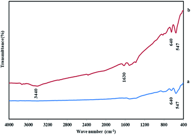
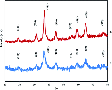
Material characterization was done with FT-IR, XRD, FE-SEM, and EDX methods. FT-IR spectroscopy is a convenient and efficient analysis for the characterization of a functionalized nanoparticle and manufacturing bonds of nanoparticles. So, firstly the structure of NiCo2O4 nanostructures was characterized by FT-IR spectroscopy. Fig. 1 shows the FT-IR of NiCo2O4. The sharp bands at 547, 640 cm−1 are due to Ni–O and Co–O vibration at octahedral and tetrahedral sites respectively are shown in both samples.26–28 The broad bands at 3440 and 1630 cm−1 are corresponding to the stretching and bending vibrations of the hydroxyl of the adsorbed water molecules.29 For the DHSANPs sample, these peaks are wider, which can be due to the presence of many traps in its structure and adsorption of more water molecules.X-ray diffraction analysis (XRD) is the most effective method for the structure and size of a crystalline nanoparticle. The XRD patterns of NiCo2O4 nanostructures are illustrated in Fig. 2. All the peaks in both samples correspond exactly to the spinel structure of NiCo2O4. The X-ray diffraction characteristic peaks at 2θ = 18.9, 31.2, 36.7, 44.6, 55.4, 59.1, 64.9, and 77°, which corresponding to plans of spinel NiCo2O4 (JCPDS no. 20-0781).24–33 No peak is observed at other angles, indicating the purity of the synthesized material. The broad diffraction peaks reveal the small size of the products.
The estimated nanocrystallite size based on Scherrer's law from the (311) line also was done:34
d = 0.9λ/β1/2![[thin space (1/6-em)]](https://www.rsc.org/images/entities/char_2009.gif) cos cos![[thin space (1/6-em)]](https://www.rsc.org/images/entities/char_2009.gif) θ θ |
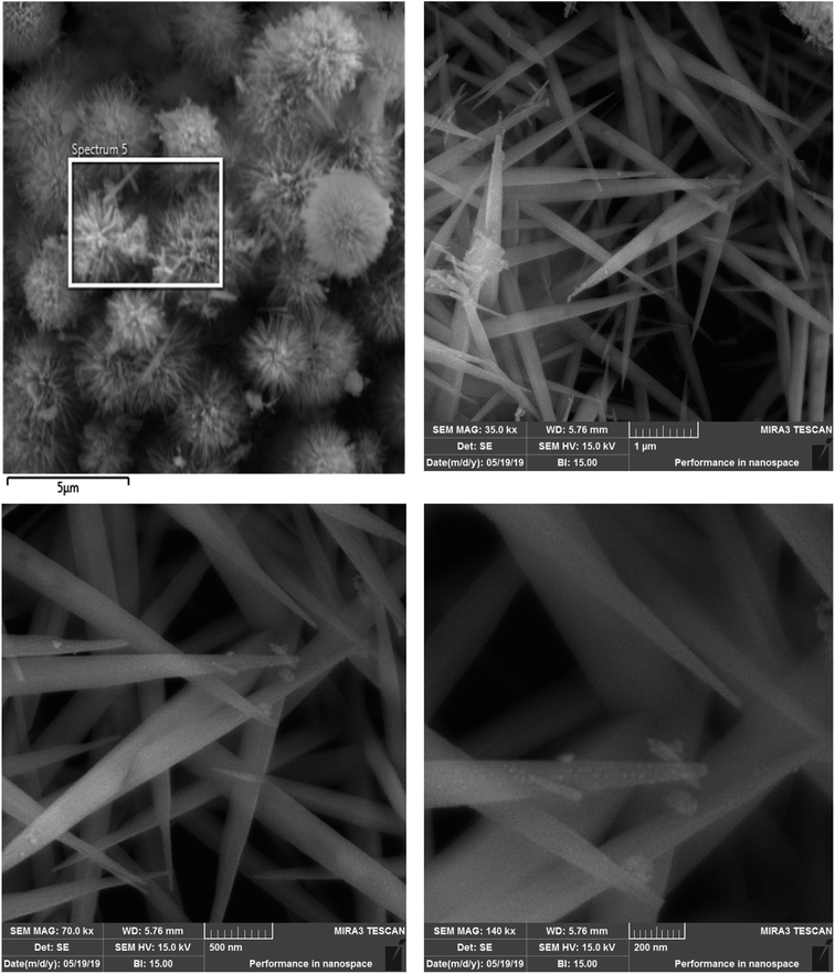
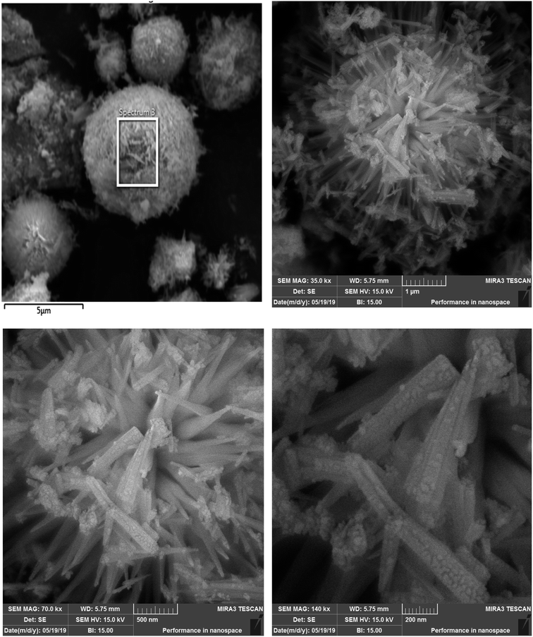
The morphological characterizations of the samples were done by FE-SEM. Fig. 3 shows surfactant-free monodispersed hierarchically self-assembled NiCo2O4 nanopins (MHSANPs) in different scales. Fig. 4 shows dense self-organized nanopins in different scales. Generally, the formation of hierarchical structures consists of five stages. The first stage is the nucleation. Secondly, the nuclei come together by a self-aggregating mechanism due to its high surface energy. Then the nanocrystals are formed. In the fourth stage, anisotropic growth is performed in pathways with optimal energy. In the end, Ostwald's process can be accomplished, and larger particles will be larger at the expense of smaller particles. This happens if the nuclei are in the supersaturated state for a longer time.15,35 The CTAB presence, allows the nuclei to remain supersaturating due to the greater stability based on the interaction between surfactant and the nanoparticles and allowed the nanoparticles to aggregate much more and the structure becomes more compact.
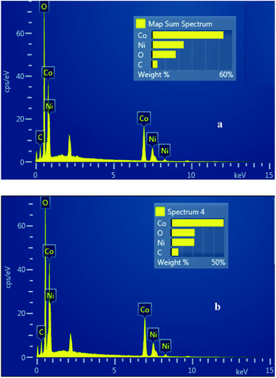
The chemical composition of the hierarchical NiCo2O4 nanostructures has been analyzed using EDS (Fig. 5). Fig. 5a shows the EDS spectrum of surfactant-free MHSANPs-NiCo2O4. The wt% value for nickel (Ni, 23.85%), cobalt (Co, 52.36%) carbon (C, 4.24%) and oxygen (O, 19.56%) also are shown. Fig. 5b shows the EDS spectrum of DHSANPs-NiCo2O4. The wt% value for nickel (Ni, 21.75%), cobalt (Co, 49.41%) carbon (C, 6.75%) and oxygen (O, 22.09%) also are shown. As can be seen, the values with an acceptable approximation are close to the stoichiometric ratio in both nanostructures. The amount of carbon shown in both samples is low (about 4–6%) and is probably due to the residues of organic matter such as urea and CTAB, which in the case of surfactant used, the amount of carbon has been increased.
3.2. Electrochemical capacity study
The electrochemical capacitive studies of the materials and fabricated working electrodes are carried out as maintained in the general electrochemical procedure. The CVs were recorded in the −0.1 to 1.0 V potential window at different scan rates in the 1 M Na2SO4 electrolyte. Fig. 6a and b shows CV curves of MHSANPs-NiCo2O4 and DHSANPs-NiCo2O4 respectively at various scan rates ranging from 10 to 100 mV s−1. The current peak at about 0.3 V and 0.5 V indicates the deintercalation and intercalation of the cation in the electrode and the electrochemical reversible redox reaction due to its faradic capacitance property can be seen.36,37 The area of the CV of dense self-organized nanopins NiCo2O4 is significantly bigger than the other. This is probably due to its compact structure and the ability to store much more ions and thus its greater faradic capacitance. In other words, the ideal and symmetrical shape, especially for the dense nanostructure, is found throughout the potential window even at a low scanning rate, indicating its high capacity and low resistance. As the scanning rate increases, the current density increased but there are no tangible changes in the shape of the curve, indicating the stability of the material.38,39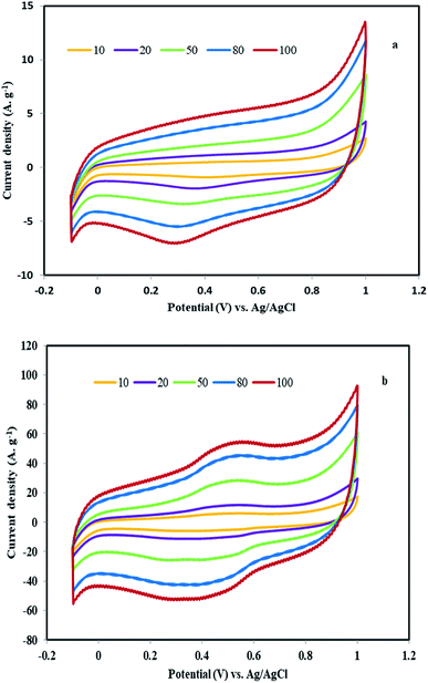 | ||
| Fig. 6 The CV curves of the MHSANPs-NiCo2O4 (a) and DHSANPs-NiCo2O4 (b) electrode at various scan rates ranged from 10 to 100 mV s−1 (b). | ||
To evaluate the real applicability of samples for supercapacitors, GCD tests were investigated at various current densities in the −0.1 to 1 V (vs. Ag/AgCl) potential window. Fig. 7a shows the GCD curve of the surfactant-free MHSANPs-NiCo2O4 with several current densities up to 20 A g−1. The specific capacitances of this sample are thus calculated to be 377, 300, 288, and 218 F g−1 at a current density of 5, 10, 15, 20 A g−1, respectively. Fig. 7b shows the GCD curve of the DHSANPs-NiCo2O4 with several current densities up to 20 A g−1. The specific capacitances of this sample are thus calculated to be 2168, 1650, 1363, and 618 F g−1 at a current density of 5, 10, 15, 20 A g−1, respectively. As can be seen, the capacitance in the dense NiCo2O4 sample is about 6 times higher, probably due to its ability to ion storage and faradic redox. For both samples, the specific capacitance decreases steadily with increasing current density due to the lack of active material participating in the redox reaction and therefore voltage drop formation at high current density in both samples. Fig. 8a illustrates the relationship between the current density of the samples and the specific capacitance. As is evident, the specific capacitance of the dense self-organized nanopins NiCo2O4 is much higher in all cases. The cycling stability of the electrodes was obtained at 5 A g−1, shows acceptable capacitance retention ratio which is above 95% and 97% for MHSANPs-NiCo2O4 and DHSANPs-NiCo2O4 respectively after 100 charge–discharge cycles (Fig. 8b).
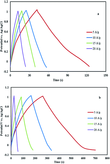 | ||
| Fig. 7 The GCD curve of the MHSANPs-NiCo2O4 (a) and DHSANPs-NiCo2O4 (b) electrode with several current densities up to 20 A g−1. | ||
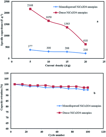 | ||
| Fig. 8 The relationship between the current density of different materials and the specific capacitance (a) and the cycling stability of the electrodes was obtained at 5 A g−1 (b). | ||
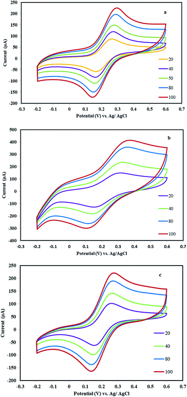
The electron transfer capability of the electrode was studied with a CV of potassium ferrocyanide/ferricyanide redox reactions. For this reason, a solution of 10.0 mM K4[Fe(CN)6] and 0.10 M KCl was used as the electrolyte in the potential of −0.20 to +0.60 V. In this study, less difference between anodic and cathode peak potentials and greater current intensity confirming better rate of electron transfer and bigger active surface at electrode base of Randles–Sevcik equation. Fig. 9a shows cycling voltammograms of bare graphite electrode at various scan rates ranged from 20 to 100 mV s−1. In this electrode, the diagram is slightly symmetrical (ΔEp = 70 mV for a scan rate of 40 mV s−1) and the Ip reaches 223 μA at the rate of 100 mV s−1. By modifying the electrode with the MHSANPs-NiCo2O4, the shape was changed and the intensity of the Ip reaches 408 μA (ΔEp = 150 mV for a scan rate of 40 mV s−1), indicating a much better electron exchange in this sample (Fig. 9b). This could be due to the presence of separate nanopins and the higher ability to electron exchange at their tips. In the case of the DHSANPs-NiCo2O4 dense self-organized nanopins NiCo2O4 electrode, it becomes more symmetrical and resembles the graphite state, which may be due to its compact state with a Ip of 218 μA at the rate of 100 mV s−1 (ΔEp = 100 mV for a scan rate of 40 mV s−1) (Fig. 9c). As can be seen, it has a low difference between anodic and cathode peak potentials indicating acceptable reversibility and confirmed suitability of this electrode material for use in the supercapacitor. In all samples, by increasing the scan rate (v) from 20 to 100 mV s−1, the peak current and peak separation potential increase with a gentle slope. As shown in Fig. 10, the redox peak currents were proportional to the square root of the scan rate for all samples, suggesting a diffusion-controlled process.40–42
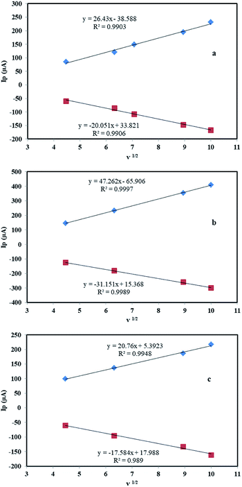 | ||
| Fig. 10 The linear relationship between the redox peak currents and the square root of the scan rate of a bare graphite electrode (a), MHSANPs-NiCo2O4 (b) and DHSANPs-NiCo2O4 (c). | ||
EIS was used as a very useful technique for studying the interface between electrode and electrolyte. Therefore EIS experiments were done in a solution of 10.0 mM K4[Fe(CN)6] and 0.10 M KCl at OCP with an AC perturbation of 5 mV in the frequency range of 0.1 Hz to 100 kHz. The equivalent circuit consists of Rs, Cdl, and Rp (Fig. 11). Rs is internal resistance is a component of the supercapacitor cell and in the Nyquist plot is the intercept value at the horizontal axis. Rp is the summation of Rct as a semicircle at high frequency due to kinetic control and RW (Warburg impedance) as a straight line at low frequency due to mass transport control. Cdl is the capacitance of the double layer.43 The data for all electrodes were fitted with the Zview (version 3.5d) software. The values of Rp for the electrodes were as follows: bare graphite (281 ohm), modified with MHSANPs-NiCo2O4 (182 ohm) and modified with DHSANPs-NiCo2O4 (237 ohm), show low electron resistance for electrodes as an important property in supercapacitor application. The lowest resistance in the MHSANPs-NiCo2O4 sample is due to the needle heads like pins and the fast electron transfer from them. These results strongly confirm the ferrocyanide/ferricyanide redox study results.
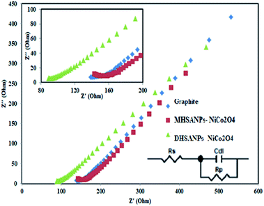 | ||
| Fig. 11 Nyquist plots of EIS analysis of bare graphite electrode, MHSANPs-NiCo2O4 and DHSANPs-NiCo2O4 in 10 mM K4Fe(CN)6 containing 0.1 M KCl and the equivalent circuit model. | ||
4. Conclusions
In the present work, a morphology controlled hydrothermal method for the synthesis of 3D hierarchically self-assembled NiCo2O4 nanopins was synthesized. By the developed method two monodisperse and dense nanopins structures were produced and successfully characterized with proper methods. The CV, GCD, and EIS tests were used for capacitance study of the materials. The dense self-organized nanopins delivered the highest specific capacitance of 2168 F g−1 at 5 A g−1 current density, with the capacity retention as high as 97% after 100 cycles. Characteristic performance by the developed method was compared with different NiCo2O4 based electrode materials. The results are shown in Table 1. As can be seen, the present study shows a straightforward synthesis procedure for the synthesis of 3D hierarchically NiCo2O4 nanopins and acceptable electrochemical performance. According to the best of our knowledge, this is the first report of carbon past as a substrate for use in supercapacitors. Because of the mentioned reasons, ensure that such material can be applied as cathodic electrode material in energy storage devices and large scale commercial applications.| Active material | Precursors, time and temperature | Morphology | Average size (nm) | Synthesis method | Electrolyte | Substrate | Capacity (F g−1) | Ref. |
|---|---|---|---|---|---|---|---|---|
| a Ethylenediaminetetraacetic acid (EDTA), polyethyleneimine (PEI), hexamethylenetetramine (HMTA), deoxyribonucleic acid (DNA), carbon nanotube (CNT). | ||||||||
| NiCo2O4 | Co(Ac)2·4H2O, Ni(Ac)2·4H2O, 3 h, 400 °C | Coral like nanoparticle | 170 | Sol–gel | KOH 1 M | Ni foam | 217 | 7 |
| NiCo2O4/meso carbon | Ni(NO3)2·6H2O, Co(NO3)2·6H2O, urea, 8 h, 95 °C | Nanoneedles | 50 | Hydrothermal | KOH 3 M | Ni foam | 458 | 26 |
| NiCo2O4 | NiCl2·6H2O, CoCl2·6H2O, urea, 6 h, 120 °C | Urchin like nanostructures | 150 | Hydrothermal | KOH 3 M | Ni foam | 1348 | 18 |
| NiCo2O4 | Co(Ac)2·4H2O, Ni(Ac)2·4H2O, CTAB, NaHCO3, 6 h, 35 °C | Hollow urchin | 15 | Sol–gel | KOH 6 M | Ni foam | 95 | 24 |
| NiCo2O4 | Co(Ac)2·4H2O, Ni(Ac)2·4H2O, urea, 5.5 h, 150 °C | Nanorods | 25 | Solvothermal | KOH 2 M | Ni foam | 600 | 22 |
| GO/MWCNT/NiCo2O4 | Ni(NO3)2·6H2O, Co(NO3)2·6H2O, urea, 8 h, 90 °C | Nanoparticles | 15 | Sol–gel | KOH 6 M | Stainless-steel | 707 | 44 |
| NiCo2O4/RGO | Ni(NO3)2·6H2O, Co(NO3)2·6H2O, NH3, 12 h, 60 °C | Nanoparticles | — | Sol–gel | KOH 6 M | Ni foam | 835 | 45 |
| NiCo2O4 | Ni(NO3)2·6H2O, Co(NO3)2·6H2O, NH4F, urea, 5 h, 100 °C | 3D hierarchical nanosheet–nanowire cluster (pine-like) | 75 | Sol–gel | KOH 2 M | Ni foam | 2000 | 19 |
| NiCo2O4-CNT@DNA | Ni(NO3)2·6H2O, Co(NO3)2·6H2O, HMTA, DNA, 5 h, 90 °C | Nanoparticle | 8 | Sol–gel | KOH 3 M | Ni foam | 760 | 46 |
| NiCo2O4 | Ni(NO3)2·6H2O, Co(NO3)2·6H2O, EDTA, PEI, 1 h, 500 °C | 3D hierarchical porous network-like | 27 | Sol–gel | KOH 3 M | Ni foam | 587 | 20 |
| NiCo2O4 | NiCl2·6H2O, CoCl2·6H2O, urea, 6 h, 180 °C | Monodisperse hierarchically self-assembled nanopins | 10 | Hydrothermal | Na2SO4 1 M | Carbon past | 377 | This work |
| NiCo2O4 | NiCl2·6H2O, CoCl2·6H2O, urea, CTAB, 6 h, 180 °C | Dense hierarchically self-assembled nanopins | 10 | Hydrothermal | Na2SO4 1 M | Carbon past | 2168 | This work |
Conflicts of interest
There are no conflicts to declare.References
- A. S. Aricò, P. Bruce, B. Scrosati, J.-M. Tarascon and W. v. Schalkwijk, Nat. Mater., 2005, 4, 366–377 CrossRef.
- P. C. Chen, G. Shen, Y. Shi, H. Chen and C. Zhou, ACS Nano, 2010, 4, 4403–4411 CrossRef CAS.
- A. K. Mondal, D. Su, S. Chen, X. Xie and G. Wang, ACS Appl. Mater. Interfaces, 2014, 6, 14827–14835 CrossRef CAS.
- M. vengari, T. Pryor and L. Jiang, J. Energy Eng., 2013, 139, 72–79 CrossRef.
- F. Fu, J. Li, Y. Yao, X. Qin, Y. Dou, H. Wang, J. Tsui, K. Chan and M. Shao, ACS Appl. Mater. Interfaces, 2017, 9, 16194–16201 CrossRef CAS.
- J. Xu, L. He, W. Xu, H. Tang, H. Liu, T. Han, Y. Zhang and C. Zhang, Electrochim. Acta, 2014, 145, 185–192 CrossRef CAS.
- Y. Q. Wu, X. Y. Chen, P. T. Ji and Q. Q. Zhou, Electrochim. Acta, 2011, 56, 7517–7522 CrossRef CAS.
- Y. Zhang, Y. Ru, H.-L. Gao, S.-W. Wang, J. Yan, K.-Z. Gao, X.-D. Jia, H.-W. Luo, H. Fang, A.-Q. Zhang and L.-Z. Wang, J. Electrochem. Sci. Eng., 2019, 9, 243–253 CrossRef CAS.
- C. Wang, E. Zhou, X. Deng, M. Shao, J. Huang, X. Wei and X. Xu, Sci. Adv. Mater., 2016, 8, 1298–1304 CrossRef CAS.
- M. Chatterjee, S. Saha, S. Das and S. K. Pradhan, J. Alloys Compd., 2020, 821, 153503 CrossRef CAS.
- J. Du, G. Zhou, H. Zhang, C. Cheng, J. Ma, W. Wei, L. Chen and T. Wang, ACS Appl. Mater. Interfaces, 2013, 5, 7405–7409 CrossRef CAS.
- D. Carriazo, J. Patino, M. C. Gutiérrez, M. L. Ferrer and F. d. Monte, RSC Adv., 2013, 3, 13690–13695 RSC.
- C. Wang, E. Zhou, W. He, X. Deng, J. Huang, M. Ding, X. Wei, X. Liu and X. Xu, Nanomaterials, 2017, 7, 1–23 Search PubMed.
- S. Hassanpoor, G. Khayatian and A. R. J. Azar, Microchim. Acta, 2015, 182, 1957–1965 CrossRef CAS.
- M. Fang, G. Dong, R. Wei and J. C. Ho, Adv. Energy Mater., 2017, 7, 1700559–1700584 CrossRef.
- Z. Ren, Y. Guo, C.-H. Liu and P.-X. Gao, Front. Chem., 2013, 1, 1–22 CAS.
- X. Liu, S. Shi, Q. Xiong, L. Li, Y. Zhang, H. Tang, C. Gu, X. Wang and J. Tu, ACS Appl. Mater. Interfaces, 2013, 17, 8790–8795 CrossRef.
- Q. Wang, B. Liu, X. Wang, S. Ran, L. Wang, D. Chen and G. Shen, J. Mater. Chem., 2012, 22, 21647–21653 RSC.
- Y. Chen, B. Qu, L. Hu, Z. Xu, Q. Li and T. Wang, Nanoscale, 2013, 5, 9812–9820 RSC.
- C. z. Yuan, J. Li, L. n. Hou, J. Lin, X. g. Zhang and S. Xiong, J. Mater. Chem. A, 2013, 1, 11145–11151 RSC.
- K. Vytras, I. Švacara and R. Metelka, J. Serb. Chem. Soc., 2009, 74, 1021–1033 CrossRef CAS.
- E. Jokar, A. I. zad and S. Shahrokhian, J. Solid State Electrochem., 2015, 19, 269–274 CrossRef CAS.
- D. Guragain, C. Z. equine, T. Poudel, D. N. eupane, R. K. Gupta and S. R. Mishra, J. Nanosci. Nanotechnol., 2020, 20, 2526–2537 CrossRef CAS.
- Y. Lei, Y. Wang, W. Yang, H. Yuan and D. Xiao, RSC Adv., 2015, 5, 7575–7583 RSC.
- S. Zhang and N. Pan, Adv. Energy Mater., 2014, 1401401, 2–19 Search PubMed.
- Y. Zhang, Y. Zhang, D. Zhang and L. Sun, Dalton Trans., 2017, 46, 9457–9465 RSC.
- H. Zhang, H. Li, H. Wang, K. He, S. Wang, Y. Tang and J. Chen, J. Power Sources, 2015, 280, 640–648 CrossRef CAS.
- K. Pandi, M. Sivakumar, S.-M. Chen, Y.-H. Cheng and T.-W. Chen, Int. J. Electrochem. Sci., 2018, 13, 1227–1240 CrossRef CAS.
- S. Liu, C. h. An, X. y. Chang, H. Guo, L. Zang, Y. Wang, H. Yuan and L. Jiao, J. Mater. Sci., 2018, 54, 2658–2668 CrossRef.
- A. K. Das, R. K. Layek, N. H. Kim, D. Jung and J. H. Lee, Nanoscale, 2014, 6, 10657–10665 RSC.
- L. J. Cardenas-Flechas, A. M. Raba and M. Rincón-Joya, Dyna, 2020, 87, 184–191 CrossRef.
- J.-C. Xing, Y.-L. Zhu and Q.-J. Jiao, J. New Mater. Electrochem. Syst., 2014, 17, 209–211 CrossRef CAS.
- G. D. Park, Y. N. Ko and Y. C. Kang, Sci. Rep., 2014, 4, 1–7 Search PubMed.
- M. H. Alfaruqi, S. Islam, J. Gim, J. Song, S. Kim, D. Pham, J. Jo, Z. Xiu, V. Mathew and J. Kim, Chem. Phys. Lett., 2016, 650, 64–68 CrossRef CAS.
- S. K. Kulkarni, Nanotechnology: Principles and Practices, Springer International Publishing, 2015 Search PubMed.
- T. Brousse, D. Bélanger and J. W. Long, J. Electrochem. Soc., 2015, 162, A5185–A5189 CrossRef CAS.
- X. Wang, Y. Fang, B. Shi, F. Huang, F. Rong and R. Que, Chem. Eng. J., 2018, 344, 311–319 CrossRef CAS.
- A. k. Mondel, B. Wang, D. Su, Y. Wang, S. Chen, X. Zhang and G. Wang, Mater. Chem. Phys., 2014, 143, 740–746 CrossRef.
- T. K. Das, S. Banerjee, A. Kumar, A. K. Debnath and V. Sudarsan, Solid State Sci., 2019, 96, 105952 CrossRef CAS.
- M. M. Rahman and I. C. Jeon, J. Braz. Chem. Soc., 2007, 18, 1150–1157 CrossRef CAS.
- X. Chen, L. Ji, Y. Zhou and K. Wu, Sci. Rep., 2016, 26044, 1–9 Search PubMed.
- S. Hassanpoor and N. Rouhi, Int. J. Environ. Anal. Chem., 2019 DOI:10.1080/03067319.2019.1669582.
- H. Tan and Z. Ren, Mater. Sci. Forum, 2016, 14, 14–21 Search PubMed.
- S. Ramesh, D. Vikraman, H.-S. Kim, H. S. Kim and J.-H. Kim, J. Alloys Compd., 2018, 765, 369–379 CrossRef CAS.
- H. W. Wang, Z. A. Hu, Y. Q. Chang, Y. L. Chen, H. Y. Wu, Z. Y. Zhang and Y. Y. Yang, J. Mater. Chem., 2011, 21, 10504–10511 RSC.
- Y. Xue, T. Chen, S. Song, P. Kim and J. Bae, Nano Energy, 2019, 56, 751–758 CrossRef CAS.
| This journal is © The Royal Society of Chemistry 2020 |


