 Open Access Article
Hydrogen evolution reaction at the interfaces of two-dimensional lateral heterostructures: a first-principles study
Huimin Huab and
Jin-Ho Choi *ab
*ab
aCollege of Energy, Soochow Institute for Energy and Materials Innovations, Soochow University, Suzhou 215006, China. E-mail: jhchoi@suda.edu.cn
bKey Laboratory of Advanced Carbon Materials and Wearable Energy Technologies of Jiangsu Province, Soochow University, Suzhou 215006, China
First published on 21st October 2020
Abstract
Owing to the synergetic effects of different two-dimensional (2D) materials, 2D heterostructures have recently attracted much attention in the field of catalysis. We present a first-principles study of hydrogen adsorption on the lateral heterostructure of graphene and h-BN, and its potential application in the hydrogen evolution reaction. The density functional theory calculations in this study show that substantial charge transfer occurs at the heterostructure interfaces, which can enhance the H adsorption on the interfacial atoms. Consequently, the adsorption free energy ΔGH* of the interfaces becomes close to zero, which is optimal for the hydrogen evolution reaction. The results also demonstrate that ΔGH* decreases monotonically with increase in the p-band center, indicating that s–p hybridization plays a crucial role in determining the adsorption strength. These findings are expected to be broadly applicable to other 2D lateral heterostructures, providing a new strategy for hydrogen production.
Introduction
Hydrogen evolution reaction (HER) is technologically crucial for producing hydrogen from water as a green energy source. Noble metals show excellent catalytic performance, but their significant drawbacks include limited resources and high production costs.1–3 Therefore, over the past several years, much effort has been devoted to improving the catalytic activity of other materials, including earth-abundant transition metal compounds, by increasing the number of active sites (e.g., using heterostructures and nanoparticles) and by modifying the electronic properties (e.g., using defects, doping, and coupling between substrates and monolayers).4–8 In particular, two-dimensional (2D) heterostructures are one of the most promising avenues for HER owing to the numerous possible combinations of different 2D materials. Specifically, heterostructure formation can not only provide more active sites at interfaces or edges and optimized electronic structures but can also render high electrical conductivity. Indeed, previous experimental and theoretical studies have demonstrated that the formation of 2D heterostructures can improve the performance of HER.9,10The two types of 2D heterostructures are vertical and lateral heterostructures. The former comprises layers stacked by van der Waals (vdW) interactions, whereas the latter connects more than two different 2D materials laterally. For example, lateral heterostructures of transition-metal dichalcogenide layers, with similar lattice constants, have been successfully fabricated using pulsed laser deposition methods.11 In the formation of lateral heterostructures, matching lattice constants is more crucial than the effects of vdW interactions, presumably limiting the selection of constituent 2D layers. However, their interfaces can be effectively tailored, thus modifying the electronic properties more dramatically, compared to vertical heterostructures. In particular, the interface formation may offer more active sites, which is desirable for electrocatalysis. However, to the best of our knowledge, studies employing 2D lateral heterostructures for catalysts are still lacking.
To date, many 2D lateral heterostructures have been either experimentally realized or theoretically proposed.12 Among them, the best-known example is the lateral heterostructures of graphene and hexagonal boron nitride (h-BN), with controllable domain size and interface pattern.13–18 In particular, a lithography technique successfully patterned alternating stripes of graphene and h-BN in the lateral heterostructure, which can provide more active interfaces.19
In this study, we use first-principles density functional theory (DFT) calculations to investigate the hydrogen (H) adsorption properties on the graphene/h-BN lateral heterostructures and to further predict the catalytic activity for HER. A considerable charge transfer modifies the electronic structures of the interfaces substantially, which can enhance the H adsorption on interfacial atoms. Consequently, ΔGH* of the interfaces approaches the optimal zero-energy criteria for the HER. Our detailed analysis further reveals that with the increase in the p-band center, ΔGH* decreases monotonically, indicating that H adsorption at the interfaces strongly depends on the s–p hybridization.
Computational methods
First-principles DFT calculations were conducted using the Vienna Ab initio Simulation Package.20 The projector-augmented wave (PAW) method and the Perdew–Burke–Ernzerhof (PBE) exchange-correlation functional were used in the calculations.21 A semi-classical dispersion correction scheme (DFT-D3)22 was employed to include the effects of the long-range vdW interactions. The optimized lattice constant for graphene and h-BN is 2.47 Å and 2.51 Å, respectively. We performed spin-polarized calculations and found that the ground states of the H-adsorbed heterostructure is still nonmagnetic. The graphene/h-BN lateral heterostructures were simulated using a periodic supercell combining zigzagged graphene and h-BN nanoribbons, based on previous experimental and theoretical studies.16–19,23 Its in-plane unit-cell length was approximately 43 Å. A vacuum space wider than 20 Å along the out-of-plane direction was adopted to prevent spurious interactions between repeated images. The unit cell included both C–B and C–N interfaces. All the atoms were allowed to completely relax until the forces exerted on each atom were less than 0.02 eV Å−1 during structural optimization. The plane-wave cutoff energy was set to 400 eV. The Brillouin zone was sampled using 1 × 4 × 1 and 1 × 8 × 1 k-meshes for the optimization of atomic structures and electronic structure calculations, respectively. The formation energy of the lateral heterostructure is defined as follows:| Eform = Etot(graphene/h-BN) − Etot(graphene) − Etot(h-BN) | (1) |
| ΔGH* = ΔEH* + ΔEZPE − TΔS | (2) |
where ρp(E) corresponds to the density of the p states of the relevant atom at energy E. The integral domain is from the minimum energy to the maximal energy of the p orbitals. For comparison, additional DFT calculations using an atomic orbital basis approach, as implemented in SIESTA, were further performed. The optimized lattice constants are 2.48 Å and 2.52 Å for graphene and h-BN, respectively, which agree well with the values from the plane-wave method. The corresponding ΔGH* are 1.65 eV and 2.56 eV, which are close to the results from the VASP calculations (1.81 eV and 2.66 eV).
Results and discussion
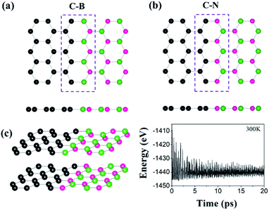
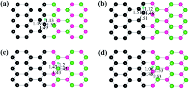
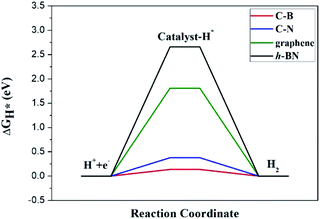
We first investigate the interface structures and stability of the graphene/h-BN lateral heterostructures. Note that patterned interfaces of the lateral heterostructure of graphene and h-BN have been achieved experimentally.13–18 Because h-BN has two types of zigzagged edges, there are two possible interfaces, the C–B and the C–N (Fig. 1(a) and (b), respectively), where a substantial charge transfer may occur. The lattice mismatch of graphene and h-BN is only 1.7%, and therefore there are no severe structural distortions at the interfaces. The calculated lengths of the C–B and C–N bonds are 1.54 Å and 1.40 Å, respectively. The formation energy of the graphene/h-BN heterostructure is −0.29 eV per interfacial atom, indicating that the heterostructure formation is energetically favorable. To further examine the thermodynamic stability of the heterostructure, we performed molecular dynamics simulations, as shown in Fig. 1(c). The final structure after the simulation of 20 ps at 300 K, together with the energy profile, shows no dramatic structural deformation, confirming that the heterostructure is thermodynamically stable at room temperature.To evaluate the catalytic activity for HER, we further investigated the H adsorption properties of the graphene/h-BN heterostructure. Here, several possible adsorption sites were considered near the interfaces. Fig. 2 displays the optimized adsorption configurations of an H atom at the C–B and C–N interfaces. The H atom can be adsorbed on top of C, N, and B atoms at the C–N interface (with only the C atom at the C–B interface), while no adsorption configurations were stable on the hollow and bridge sites. Hereinafter, we refer to the X adsorption configurations. Note that ΔEH* is calculated with respect to the site at the C–B(N) interface as XB(N). Table 1 provides the calculated adsorption energies (ΔEH*) for the possible total energy of H2. HER catalysis includes two main stages. The first is the electrochemical hydrogen adsorption (H+ + e− → H*), referred to as the Volmer reaction, where H* represents an adsorbed H atom. The second part is the desorption process, referred to as the Heyrovsky reaction (H* + H+ + e− → H2) or the Tafel reaction (H* + H* → H2). A moderate ΔEH* is desirable for the HER to facilitate the desorption reactions. In this regard, the CB and CN sites show a balanced ΔEH* (−0.20 and 0.01 eV) for both the adsorption and desorption steps.
| Adsorption site | ΔEH* (eV) | ΔGH* (eV) |
|---|---|---|
| CB | −0.20 | 0.14 |
| CN | 0.01 | 0.38 |
| NN | 1.91 | 2.28 |
| BN | 2.64 | 2.96 |
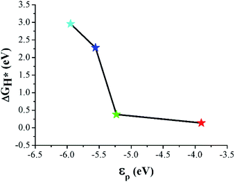
The Gibbs free energy of H adsorption (ΔGH*) is a broadly used descriptor for the catalytic activity for HER.24,25 Specifically, zero free energy is optimal for HER performance. Both graphene and h-BN individually have a much higher ΔGH*, which is far from the best criteria.26 Indeed, it has been found experimentally that graphene and h-BN are unsuitable for HER.27,28 Our DFT calculations confirm the poor catalytic activities of graphene and h-BN, as reflected by the corresponding ΔGH* (1.81 eV and 2.66 eV), consistent with the experimental observations. However, the heterostructure formation reduces ΔGH* significantly, and the values for the CB and CN sites become 0.14 eV and 0.38 eV, respectively, which is comparable to that (ca. 0.1 eV)29 of Pt catalysts (Fig. 3). These data suggest that the lateral heterostructure can exhibit a much improved catalytic activity for the HER.
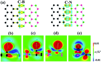
To obtain more insights into the dramatic changes in ΔGH*, we explored the electronic structures of the heterostructure interfaces. Fig. 4(a) plots the charge density difference of clean graphene/h-BN heterostructure prior to H adsorption for the C–B and C–N interfaces. Here, the plot was obtained by individually subtracting the densities of graphene and h-BN from that of the heterostructure, which can describe changes in the charge distribution near the interfaces. This shows a substantial charge transfer from the interfacial B atoms to the neighboring C or N atoms at both the interfaces. Notably, previous experimental works also show that the presence of the edges or interfaces of MoS2 or its heterostructures can improve the catalytic activity for HER.30,31 Bader charge analysis also demonstrates that the B atoms donate approximately two electrons to the neighboring atoms. The N atoms gain the majority of the donated charges. Interestingly, the CB site accepts ∼0.7 e, while the CN site loses ∼0.4 e, implying different electronic configurations of the interfacial C atoms. Further, the calculated bond energies are −5.98 and −5.82 eV for the C–B and C–N interfaces, respectively, which indicates that the former is more strongly bound than the latter. It is noteworthy that as the binding strength between the adatom and the substrate becomes stronger, its ΔGH* decreases;32 a trend also observed in our work.
Panels (b–e) in Fig. 4 depict the charge density differences due to the H adsorption at the interfaces. The CB, CN, and BN sites show the charge distribution of an sp3 σ bonding, while the NN site shows no pronounced bonding configuration between the H and N atoms. Bader charge analysis further demonstrates that the total charge of the H atom changes only slightly on CB and CN, compared with BN and NN (Table 2). Overall, our data indicate that the H atoms form a covalent bond with the C atoms, which enhances the H adsorption at the interfaces.
| Adsorption site | ne |
|---|---|
| CB | −0.07 |
| CN | −0.05 |
| NN | −0.40 |
| BN | 0.34 |
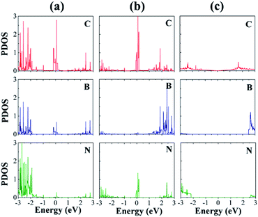
We now discuss the electronic structures of the interfaces. Fig. 5 displays the atom-decomposed density of states (DOS) for the clean interfaces without H. The DOSs, especially those of the C atoms, show dramatic changes near the Fermi level (EF) owing to the heterostructure formation. In contrast to the semimetallic DOS of graphene, both the CB and CN sites have much higher peaks at EF, which originate mainly from the C p orbitals. The abundant DOS at EF likely increases the electrical conductivity of the material, which is also crucial to the HER catalytic performance.32 The C–B interface possesses considerably more occupied states below EF than the C–N interface, which may indicate that the former has more available electrons for hybridization with the s orbital of H.33
We investigated the local DOS of the interfacial atoms after the H adsorption (Fig. 6). For the purpose of plotting, we selected the sites where H atom was adsorbed. The peaks at EF disappear for the CB and CN sites because of the adsorption, which indicates a strong hybridization of the C p orbitals with the H s orbitals, similar to the cases of 2D transition metal dichalcogenides.34 This hybridization is in stark contrast to the case of pristine graphene, where a sharp peak of the H s orbital appears at EF in the DOS (Fig. 6(e)). This result accounts for the enhanced H adsorption on the interfacial C atoms.
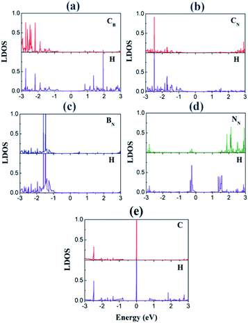 | ||
| Fig. 6 Local DOS (LDOS) of the adsorption sites with H: (a) CB, (b) CN, (c) BN, and (d) NN. For comparison, the LDOSs of the adsorbed H and the adsorption site of graphene are also displayed in (e). | ||
Band center models have been widely used as a descriptor for the catalytic activity of various metallic substrates.35–37 The C–B and C–N interfaces showed a metallic DOS originating from the interfacial p orbitals. Therefore, we calculated the p-band center (εp) of the interfacial atoms to examine the band center theory for the HER catalytic activity of the sites. Here, εp was obtained by setting the integral domain as [−∞, 0]. As shown in Fig. 7, ΔGH* decreases monotonically as εp increases. Moreover, εp of CB is closest to EF among the considered sites, which, based on the band center picture, predicts that CB has the largest Eads. This is because the hybridization of X (X = C, B, and N) p and H s orbitals becomes stronger as εp approaches EF,38 which is consistent with our DFT results.
Conclusion
In this study, we have investigated the adsorption properties of atomic H on the interfaces of graphene/h-BN lateral heterostructures. The heterostructure formation leads to a considerable charge transfer at the interfaces, which can remarkably promote the catalytic performances compared with pristine graphene and h-BN. The result also demonstrated that the interfacial C atoms, CB, and CN, have much lower Eads, close to zero, implying that they are active sites for HER catalysis. We further revealed that ΔGH* decreases monotonically with increasing εp, which accounts for the enhanced adsorption at the interfaces. These findings may have important implications for 2D materials-based hydrogen production, as well as provide more clues for further researches on metal-free 2D catalytic materials.Conflicts of interest
There are no conflicts to declare.Acknowledgements
This work was supported by the National Natural Science Foundation of China (grant no. 11874044). The DFT calculations were performed on TianHe-1(A) at the NSCC in Tianjin.Notes and references
- Y. Yan, C. S. Jiang, R. Noufi, S. H. Wei, H. R. Moutinho and M. M. Al-Jassim, Phys. Rev. Lett., 2007, 99(23), 2–5 Search PubMed
.
- K. Durose, P. R. Edwards and D. P. Halliday, J. Cryst. Growth, 1999, 197(3), 733–742 CrossRef CAS
.
- Y. C. Hu, Y. Z. Wang, R. Su, C. R. Cao, F. Li, C. W. Sun, Y. Yang, P. F. Guan, D. W. Ding and Z. L. Wang, et al., Mater, 2016, 28(46), 10293–10297 CAS
.
- R. D. Nikam, A. Y. Lu, P. A. Sonawane, U. R. Kumar, K. Yadav, L. J. Li and Y. T. Chen, ACS Appl. Mater. Interfaces, 2015, 7(41), 23328–23335 CrossRef CAS
.
- L. Yang, W. Zhou, D. Hou, K. Zhou, G. Li, Z. Tang, L. Li and S. Chen, Nanoscale, 2015, 7(12), 5203–5208 RSC
.
- D. Y. Wang, M. Gong, H. L. Chou, C. J. Pan, H. A. Chen, Y. Wu, M. C. Lin, M. Guan, J. Yang and C. W. Chen, et al., J. Am. Chem. Soc., 2015, 137(4), 1587–1592 CrossRef CAS
.
- Q. Qu, J. H. Zhang, J. Wang, Q. Y. Li, C. W. Xu and X. Lu, Sci. Rep., 2017, 7, 1–9 CrossRef
.
- X. Zou, Y. Liu, G. D. Li, Y. Wu, D. P. Liu, W. Li, H. W. Li, D. Wang, Y. Zhang and X. Zou, Adv. Mater., 2017, 29(22), 1700404 CrossRef
.
- S. H. Noh, J. Hwang, J. Kang, M. H. Seo, D. Choi and B. Han, J. Mater. Chem. A, 2018, 6, 0005–20014 RSC
.
- R. K. Biroju, D. Das, R. Sharma, S. Pal, L. P. L. Mawlong, K. Bhorkar, A. K. Singh and T. N. Narayanan, ACS Energy Lett., 2017, 2, 1355–1362 CrossRef CAS
.
- F. Ullah, Y. Sim, C. T. Le, M. J. Seong, J. I. Jang, S. H. Rhim, B. C. Tran Khac, K. H. Chung, K. Park and Y. Lee, et al., ACS Nano, 2017, 11(9), 8822–8829 CrossRef CAS
.
- T. A. Shifa, F. Wang, Y. Liu and J. He, Adv. Mater., 2019, 31(45), 1804828 CrossRef CAS
.
- M. P. Levendorf, C. J. Kim, L. Brown, P. Y. Huang, R. W. Havener, D. A. Muller and J. Park, Nature, 2012, 488(7413), 627–632 CrossRef CAS
.
- P. Sutter, R. Cortes, J. Lahiri and E. Sutter, Nano Lett., 2012, 12(9), 4869–4874 CrossRef CAS
.
- P. Sutter, Y. Huang and E. Sutter, Nano Lett., 2014, 14(8), 4846–4851 CrossRef CAS
.
- Z. Liu, L. Ma, G. Shi, W. Zhou, Y. Gong, S. Lei, X. Yang, J. Zhang, J. Yu and K. P. Hackenberg, et al., Nat. Nanotechnol., 2013, 8(2), 119–124 CrossRef CAS
.
- L. Liu, J. Park, D. A. Siegel, K. F. McCarty, K. W. Clark, W. Deng, L. Basile, J. C. Idrobo, A.-P. Li and G. Gu, Science, 2014, 343(6167), 163–167 CrossRef CAS
.
- M. Liu, Y. Li, P. Chen, J. Sun, D. Ma, Q. Li, T. Gao, Y. Gao, Z. Cheng and X. Qiu, et al., Nano Lett., 2014, 14(11), 6342–6347 CrossRef CAS
.
- G. Kim, H. Lim, K. Y. Ma, A. R. Jang, G. H. Ryu, M. Jung, H. J. Shin, Z. Lee and H. S. Shin, Nano Lett., 2015, 15(7), 4769–4775 CrossRef CAS
.
- G. Kresse and J. Furthmüller, Phys. Rev. B: Condens. Matter Mater. Phys., 1996, 54(16), 11169–11186 CrossRef CAS
.
- J. P. Perdew, K. Burke and M. Ernzerhof, Phys. Rev. Lett., 1996, 77(18), 3865–3868 CrossRef CAS
.
- S. Grimme, J. Antony, S. Ehrlich and H. Krieg, J. Chem. Phys., 2010, 132(15), 154104 CrossRef
.
- D. Zhang, D. B. Zhang, F. Yang, H. Q. Lin, H. Xu and K. Chang, 2D Mater, 2015, 2(4), 041001 CrossRef
.
- B. Hinnemann, P. G. Moses, J. Bonde, K. P. Jørgensen, J. H. Nielsen, S. Horch, I. Chorkendorff and J. K. Nørskov, J. Am. Chem. Soc., 2005, 127(15), 5308–5309 CrossRef CAS
.
- J. Rossmeisl, Z. W. Qu, H. Zhu, G. J. Kroes and J. K. Nørskov, J. Electroanal. Chem., 2007, 607(1–2), 83–89 CrossRef CAS
.
- S. Sarkar and S. C. Peter, Inorg. Chem. Front., 2018, 5(9), 2060–2080 RSC
.
- D. N. Sredojević, M. R. Belić and Ž. Šljivančanin, J. Phys. Chem. C, 2020, 124, 16860–16867 CrossRef
.
- V. K. Yadav, S. H. Mir and J. K. Singh, ChemPhysChem, 2019, 20, 687–694 CrossRef CAS
.
- X. Zou and Y. Zhang, Chem. Soc. Rev., 2015, 44(15), 5148–5180 RSC
.
- G. Ye, Y. Gong, J. Lin, B. Li, Y. He, S. T. Pantelides, W. Zhou, R. Vajtai and P. M. Ajayan, Nano Lett., 2016, 16, 1097–1103 CrossRef CAS
.
- Q. Liu, Q. Fang, W. Chu, Y. Wan, X. Li, W. Xu, M. Habib, S. Tao and Y. Zhou, et al., Chem. Mater., 2017, 29, 4738–4744 CrossRef CAS
.
- T. Wang, G. Yu, J. Liu, X. Huang and W. Chen, Phys. Chem. Chem. Phys., 2019, 21(4), 1773–1783 RSC
.
- A. Huang, K. N. Dinh, X. Sun, Q. Yan and Z. Wang, Appl. Surf. Sci., 2019, 496, 143741 CrossRef CAS
.
- S. H. Lin and J. L. Kuo, Phys. Chem. Chem. Phys., 2015, 17(43), 29305–29310 RSC
.
- Y. Zheng, Y. Jiao, M. Jaroniec and S. Z. Qiao, Angew. Chem., Int. Ed., 2015, 54(1), 52–65 CrossRef CAS
.
- S. Liu, Z. Li, C. Wang, W. Tao, M. Huang, M. Zuo, Y. Yang, K. Yang, L. Zhang and S. Chen, et al., Nat. Commun., 2020, 11(1), 938 CrossRef CAS
.
- A. Nilsson, L. G. M. Pettersson, B. Hammer, T. Bligaard, C. H. Christensen and J. K. Nørskov, Catal. Lett., 2005, 100(3–4), 111–114 CrossRef CAS
.
- W. Ji, X. Chu, S. Zhang, D. Wang and Y. Ma, Int. J. Hydrogen Energy, 2018, 43(42), 19432–19437 CrossRef CAS
.
| This journal is © The Royal Society of Chemistry 2020 |


