 Open Access Article
Highly efficient electrocatalytic hydrogen evolution promoted by O–Mo–C interfaces of ultrafine β-Mo2C nanostructures†
Hui
Yang
ab,
Xing
Chen
c,
Guoxiang
Hu
d,
Wan-Ting
Chen
e,
Siobhan J.
Bradley
f,
Weijie
Zhang
b,
Gaurav
Verma
b,
Thomas
Nann
f,
De-en
Jiang
 g,
Paul E.
Kruger
 h,
Xiangke
Wang
 *a,
He
Tian
*c,
Geoffrey I. N.
Waterhouse
e,
Shane G.
Telfer
 i and
Shengqian
Ma
 *b
*b
aCollege of Environmental Science and Engineering, North China Electric Power University, Beijing, 102206, P. R. China. E-mail: xkwang@ncepu.edu.cn
bDepartment of Chemistry, University of South Florida, 4202 E. Fowler Avenue, Tampa, Florida 33620, USA. E-mail: sqma@usf.edu
cCenter of Electron Microscopy, Zhejiang University, Hangzhou 310027, P. R. China. E-mail: hetian@zju.edu.cn
dCenter for Nanophase Materials Sciences, Oak Ridge National Laboratory, Oak Ridge, Tennessee 37831, USA
eMacDiarmid Institute for Advanced Materials and Nanotechnology, School of Chemical Sciences, The University of Auckland, Auckland 1142, New Zealand
fMacDiarmid Institute for Advanced Materials and Nanotechnology, School of Chemical and Physical Sciences, Victoria University of Wellington, Wellington 6140, New Zealand
gDepartment of Chemistry, University of California, Riverside, California 92521, USA
hMacDiarmid Institute for Advanced Materials and Nanotechnology, School of Physical and Chemical Sciences, University of Canterbury, Christchurch 8140, New Zealand
iMacDiarmid Institute for Advanced Materials and Nanotechnology, Institute of Fundamental Sciences, Massey University, Palmerston North 4442, New Zealand
First published on 12th March 2020
Abstract
Optimizing interfacial contacts and thus electron transfer phenomena in heterogeneous electrocatalysts is an effective approach for enhancing electrocatalytic performance. Herein, we successfully synthesized ultrafine β-Mo2C nanoparticles confined within hollow capsules of nitrogen-doped porous carbon (β-Mo2C@NPCC) and found that the surface layer of molybdenum atoms was further oxidized to a single Mo–O surface layer, thus producing intimate O–Mo–C interfaces. An arsenal of complementary technologies, including XPS, atomic-resolution HAADF-STEM, and XAS analysis clearly reveals the existence of O–Mo–C interfaces for these surface-engineered ultrafine nanostructures. The β-Mo2C@NPCC electrocatalyst exhibited excellent electrocatalytic activity for the hydrogen evolution reaction (HER) in water. Theoretical studies indicate that the highly accessible ultrathin O–Mo–C interfaces serving as the active sites are crucial to the HER performance and underpinned the outstanding electrocatalytic performance of β-Mo2C@NPCC. This proof-of-concept study opens a new avenue for the fabrication of highly efficient catalysts for HER and other applications, whilst further demonstrating the importance of exposed interfaces and interfacial contacts in efficient electrocatalysis.
Introduction
Electrochemically splitting water to produce hydrogen is integral to the future of sustainable energy.1 In general, Pt-based materials are highly active and stable catalysts for the hydrogen evolution reaction (HER).2,3 However, the scarcity and high cost of Pt and other precious metal-based HER catalysts limits their practicality for large-scale applications. To overcome these drawbacks while maintaining or improving catalytic activity, precious metal-free electrocatalysts are highly sought after.4,5Recently, earth-abundant transition metal carbides such as iron carbide,6 nickel carbide,7 tungsten carbide8,9 and particularly molybdenum carbide (Mo2C)10–13 have emerged as potential substitutes for precious metal-based materials as HER electrocatalysts. It was found that the HER activity of Mo2C materials can be significantly improved by fabrication of Mo2C-based heterostructures such as Mo2N–Mo2C,14,15 MoC–Mo2C,16 Ni/Mo2C-PC,17 NiMo2C/NF,18 MoxC/Ni,19 nw-W4Mo,20 and others.21–26 The high activity of these heterostructures derives from synergistic electron transfer and mass transfer phenomena.
Since catalysis takes place on the exposed surfaces/interfaces of the catalysts, Mo2C surfaces or their heterostructure interfaces can be considered to be as the active sites for HER catalysis. However, the surface metal atoms of Mo2C and other carbide catalysts are easily oxidized in aerobic environments, creating a thin adherent surface oxide layer.22,23,27–29 In previous reports, the existence of Mo in low and high valence states is commonly observed in Mo2C nanomaterials, with Mo2+, Mo4+ and Mo6+ frequently being seen by XPS.15,23,30–33 The 4+ and 6+ oxidation states generally result from surface oxidation of Mo2C, with their role in the HER over Mo2C-based catalysts having received little attention to date. It is probable that O–Mo–C interfaces are ubiquitous in Mo2C catalysts, though this aspect has not been examined in much detail. This is a notable oversight since highly oxidized Mo centers are likely to be productive sites for the generation of H2 from protons.
In this work, we aimed to probe the role of a thin well-defined oxide layer and O–Mo–C interfaces on the HER activity of Mo2C supported on N-doped carbon. Ultrafine β-Mo2C nanoparticles (β-Mo2CNPs) confined within hollow capsules of N-doped porous carbon (denoted as β-Mo2C@NPCC) were successfully prepared by pyrolysis of ZIF-8 nanocrystals coated with a molybdenum–tannic acid coordination polymer. We further discovered that the surface layer of molybdenum atoms was immediately in situ oxidized to an atomic Mo–O surface layer when exposed to air. This approach ensured strong interfacial coupling between the surface oxidized Mo atoms and underlying β-Mo2C, creating an optimized O–Mo–C surface electron transfer pathway for efficient electrocatalysis. On account of the abundant O–Mo–C interfaces, β-Mo2C@NPCC exhibited outstanding electrocatalytic activity for HER, requiring overpotentials of only 80 and 132 mV to reach catalytic current densities of 10 mA cm−2 in 0.5 M H2SO4 and 1 M KOH, respectively. The corresponding Tafel slopes were remarkably low (only 40 mV dec−1 in H2SO4 and 49 mV dec−1 in KOH, respectively). The benefits of O–Mo–C nanointerfaces to the exceptional HER performance of β-Mo2C@NPCC was confirmed by theoretical calculations. Our work paves a new way for the rational development of next-generation catalysts for HER.
Results and discussion
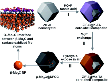
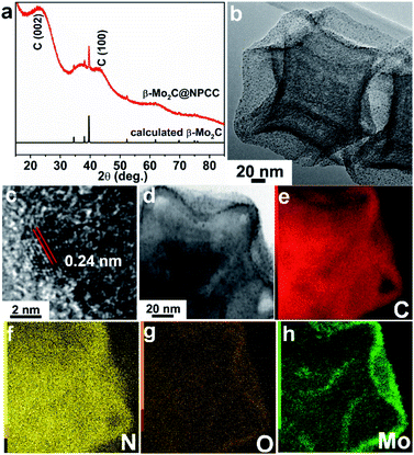
To meet the challenges of synthesizing a well-defined β-Mo2C/carbon electrocatalyst with ultrathin O–Mo–C interfaces, we sought to align the requisite elements in a well-defined precursor material, which upon pyrolysis, would produce the desired product (Scheme 1). We first prepared ZIF-8 nanocrystals, then subsequently deposited a potassium–tannic acid (K–TA) coordination polymer on their surface to deliver a ZIF-8@K–TA composite (Step I, Scheme 1).34,35 Replacement of the potassium cations in the K–TA shell by Mo(II) was achieved by simply dispersing ZIF-8@K–TA with stirring in a methanolic solution of molybdenum acetate for five hours (Step II, Scheme 1, Fig. S4 and S5†). Powder X-ray diffraction (PXRD) patterns showed that the crystallinity of the ZIF core was retained whilst the Mo–TA shell of ZIF-8@Mo–TA was amorphous (Fig. S1†). The ZIF-8@Mo–TA composite contained 1.74 wt% molybdenum by ICP-AES analysis. Pyrolysis of this material at 950 °C produced β-Mo2C@NPCC via an in situ carbonization process involving the Mo–TA shell and the organic components of the ZIF-8 nanocrystals (Step III, Scheme 1). The surface molybdenum atoms of β-Mo2C were then in situ oxidized into an ultrathin Mo–O layer by exposure to air at ambient temperature, affording final β-Mo2C@NPCC product with abundant O–Mo–C interfaces.As anticipated, β-Mo2C@NPCC retained the same overall morphology of ZIF-8@Mo–TA but was hollow with the capsule walls comprised largely of N-doped porous carbon (Fig. 1a, b, S5 and S6†). The PXRD pattern of β-Mo2C@NPCC exhibits broad peaks at 26° and 43° associated with graphitic carbon together with a sharper peak at 39.6° corresponding to the (101) plane of hexagonal β-Mo2C (Fig. 1a).33,36,37 Transmission electron microscopy (TEM) revealed that the β-Mo2C is present in the form of ultrafine nanoparticles embedded in the walls of the hollow carbon capsules (Fig. 1b). The nanoparticles have an average width of only 1.51 nm and thus can be classified as ultrafine (Fig. S8†). A high resolution-TEM (HRTEM) image of an individual nanoparticle (NP) clearly reveals lattice fringes with an interplanar spacing of 2.4 Å, corresponding to the β-Mo2C (101) plane (Fig. 1c). Scanning transmission electron microscopy (STEM) images and corresponding elemental maps for C, N, O and Mo confirmed that the surface oxidized β-Mo2C NPs were uniformly dispersed throughout the hollow N-doped carbon capsules (Fig. 1d–h).
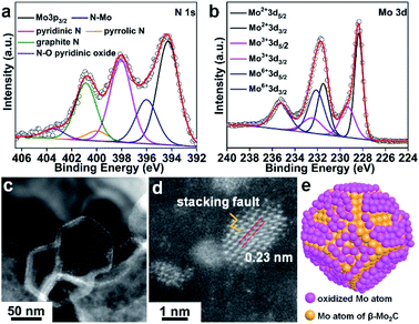
The XPS survey spectrum of β-Mo2C@NPCC confirmed the presence of molybdenum, oxygen, carbon, and nitrogen (Fig. 2a, b and S10†). The N 1s XPS spectrum showed five different nitrogen species: coordinated Mo–N (396.1 eV),14,15,31,38 pyridinic N (398.1 eV), pyrrolic N (400.1 eV), graphitic N (401.0 eV) and quaternary N (403.6 eV).14,15,31,33,37–39 The Mo–N species presumably existed at the interface between the ultrafine β-Mo2C nanoparticles and the N-doped carbon support. The Mo 3d spectrum for β-Mo2C@NPCC showed peaks at 228.3 and 231.4 eV in a 3![[thin space (1/6-em)]](https://www.rsc.org/images/entities/char_2009.gif) :
:![[thin space (1/6-em)]](https://www.rsc.org/images/entities/char_2009.gif) 2 area ratio, which can readily be assigned the Mo 3d5/2 and 3d3/2 signals, respectively, of Mo2+ in Mo2C.33,37,38 Mo species in higher valence states (e.g. Mo3+ and Mo6+) were also found by XPS. The peaks at 229.1 eV and 232.8 eV correspond to Mo3+ in Mo2N, again suggesting the presence of Mo–N type bonds between the β-Mo2C nanoparticles and the N-doped carbon matrix.14,15,31,38 We do not exclude the possibility that Mo3+ single-atom catalyst (SAC) sites (i.e. porphyrin-like Mo(III)N4 sites) may exist on the surface of the N-doped carbon capsules, though the high coverage of the ultrafine β-Mo2C nanoparticles would perhaps make the presence of such Mo(III) SAC sites unlikely in this instance. The peaks at 232.2 eV and 235.9 eV are typical features of Mo6+ in Mo–O, which arise from the mild surface oxidation of the β-Mo2C nanoparticles in air.22 The O 1s spectrum for β-Mo2C@NPCC contained three components (Fig. S10b†). The low binding energy component located at 530.4 eV is due to lattice oxygen in Mo–O. The peaks centered at 531.8 and 533.2 eV are assigned to the oxygen defects in the Mo–O layer and adsorbed hydroxyl species, respectively.
2 area ratio, which can readily be assigned the Mo 3d5/2 and 3d3/2 signals, respectively, of Mo2+ in Mo2C.33,37,38 Mo species in higher valence states (e.g. Mo3+ and Mo6+) were also found by XPS. The peaks at 229.1 eV and 232.8 eV correspond to Mo3+ in Mo2N, again suggesting the presence of Mo–N type bonds between the β-Mo2C nanoparticles and the N-doped carbon matrix.14,15,31,38 We do not exclude the possibility that Mo3+ single-atom catalyst (SAC) sites (i.e. porphyrin-like Mo(III)N4 sites) may exist on the surface of the N-doped carbon capsules, though the high coverage of the ultrafine β-Mo2C nanoparticles would perhaps make the presence of such Mo(III) SAC sites unlikely in this instance. The peaks at 232.2 eV and 235.9 eV are typical features of Mo6+ in Mo–O, which arise from the mild surface oxidation of the β-Mo2C nanoparticles in air.22 The O 1s spectrum for β-Mo2C@NPCC contained three components (Fig. S10b†). The low binding energy component located at 530.4 eV is due to lattice oxygen in Mo–O. The peaks centered at 531.8 and 533.2 eV are assigned to the oxygen defects in the Mo–O layer and adsorbed hydroxyl species, respectively.
Atomic resolution high-angle annular dark-field scanning transmission electron microscopy (HAADF-STEM) was used to elucidate the form of the molybdenum-containing nanostructures (Fig. 2c and d). The fringes with a lattice spacing of 0.23 nm can be indexed to the (101) plane of hexagonal β-Mo2C. Moreover, some crystal stacking faults can be observed in a side profile of the nanoparticles (Fig. 2d), which may arise from the lattice mismatch between β-Mo2C and peripheral Mo–O atomic layers. A schematic model of the O–Mo–C interfaces present on the surface of the ultrafine β-Mo2C nanoparticles contained within β-Mo2C@NPCC is shown in Fig. 2e.
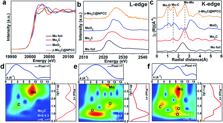
X-ray absorption spectroscopy (XAS) was applied to probe the local coordination of molybdenum in β-Mo2C@NPCC. Mo foil, Mo2C and MoO3 were used as reference materials. Normalized X-ray absorption near edge structure (XANES) spectra at the Mo K-edge absorption edge revealed β-Mo2C@NPCC contained Mo environments similar to those found in the Mo2C and MoO3 references, implying the presence of both Mo2+ and Mo6+ (Fig. 3a).40 The Mo L-edge XANES spectrum of β-Mo2C@NPCC was broad, consistent with the presence of Mo in mixed states (likely Mo2+ in Mo2C and Mo6+ in MoO3) (Fig. 3b). Extended X-ray absorption fine structure (EXAFS) analyses on the Mo K-edge data enabled further investigation of the Mo coordination environment in β-Mo2C@NPCC. The sample displayed well-resolved peaks at 1.03 Å (Mo–O), 1.51 Å (Mo–C/O), and 2.60 Å (Mo–Mo) in R-space, which could be fitted using Mo–O and Mo–C scattering paths (Fig. 3c).41,42 Thus, the EXAFS data provides strong evidence for the presence of Mo6+–O and Mo2+–C first coordination shells in the surface oxidized ultrafine β-Mo2C nanoparticles of β-Mo2C@NPCC (Fig. S11 and S12†). In the XPS analysis of β-Mo2C@NPCC, a Mo3+–N species was identified, presumably existing at the interface between the β-Mo2C and N-doped carbon support. Such a feature was not discerned (or fitted) in the EXAFS spectra, as it was likely swamped or overlapped with the signals from the Mo–O and Mo–C components. Attempts to fit the data using structural models composed of exclusively Mo–N scattering path afforded inferior fit statistics than the Mo–O and Mo–C paths, and was thus rejected. Wavelet transform EXAFS (WT-EXAFS) was performed as a means of providing a radial distance resolution in the k and R space. Mo K-edge WT-EXAFS spectra for Mo2C, MoO3 and β-Mo2C@NPCC are shown in Fig. 3d–f. Compared with Mo2C and MoO3, which showed almost exclusively Mo–C and Mo–O bonding, respectively, β-Mo2C@NPCC was found to possess both Mo–C and Mo–O bonding (Fig. 3f). Taken collectively, the PXRD, STEM, XPS and XAS results provide solid experimental evidence for the existence of ultrafine β-Mo2C nanoparticles with intimate contact surface O–Mo–C in β-Mo2C@NPCC. This result is somewhat intuitive since the surface Mo–O layer was created by air oxidation of β-Mo2C.
β-Mo2C@NPCC contained 3.0 wt% nitrogen and 4.07 wt% molybdenum, as determined by elemental analysis and ICP-AES, respectively (Table S1†). The Raman spectrum of the β-Mo2C@NPCC exhibited D (1350 cm−1) and G (1590 cm−1) bands typical of graphitic carbon, therefore the carbon capsules were anticipated to possess good electrical conductivity (Fig. S13†). The BET surface area of β-Mo2C@NPCC, calculated from a N2 adsorption isotherm collected at 77 K, was 670 m2 g−1 (Fig. S14 and Table S1†). Pronounced hysteresis loops became evident during the N2 desorption/desorption phases suggesting the existence of semi-closed (“ink-bottle”) pores in the materials. Pore size distributions, estimated from the experimental isotherms based on a DFT model, confirmed the hierarchical pore structure of the capsules with the void diameters predominantly distributed around 10 Å, 30 Å and 50 Å (Fig. S15†). The large surface area and porous structure of β-Mo2C@NPCC were expected to impart excellent electrocatalytic performance, which was confirmed below.
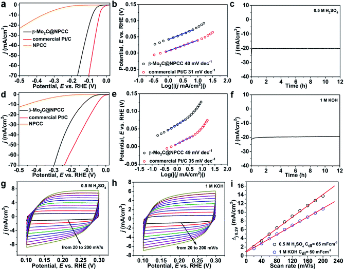
β-Mo2C@NPCC presents a range of appealing characteristics as an electrocatalytic material, including ultrafine β-Mo2C nanoparticles with abundant O–Mo–C interfaces as well as a porous and conductive N-doped carbon support matrix. The high porosity will facilitate access to active sites by offering abundant channels for mass transport. Nitrogen doping reduces the hydrophobicity of the carbon support, and pyridinic nitrogen is known to benefit electrocatalysis.39 In this light, β-Mo2C@NPCC was evaluated as an electrocatalyst for the hydrogen evolution reaction (HER) in both acidic and alkaline media. For comparison, the HER activities of a commercial Pt/C catalyst (20 wt% Pt) and molybdenum-free nitrogen-doped porous carbon capsules (NPCC) were also measured under the same testing conditions. The results are summarized in Fig. 4 and Table S4.† The polarization curves show that the HER onset potential of β-Mo2C@NPCC (36 mV) was very close to that of commercial Pt/C (20 wt% Pt) in an N2-purged 0.5 M H2SO4 electrolyte (Fig. 4a and Table S4†). β-Mo2C@NPCC required an overpotential of about 80 mV to achieve a current density of 10 mA cm−2, which indicates that the material is an outstanding catalyst for electrocatalytic hydrogen production. Turnover frequencies (TOFs) provided further confirmation of the efficiency of β-Mo2C@NPCC as a catalyst for HER. On the basis of its Mo content, β-Mo2C@NPCC has approximately 2.55 × 10¹⁶ Mo sites per cm2. If all of these sites are considered to be active, i.e. accessible to incoming substrates and catalytically competent, the TOF is 0.22 s−1 at an overpotential of 50 mV (Fig. S16†). This value indicates that the performance of β-Mo2C@NPCC is similar to, or superior to, the best high performance HER catalysts reported in the literature (Tables S6 and S7†).10,14,15,17–19,31,33,37–39,43–45
To understand the underlying mechanism of the outstanding HER activity of β-Mo2C@NPCC in detail, Tafel plots based on LSV curves were acquired (Fig. 4b). Tafel plots indicate that β-Mo2C@NPCC has outstanding kinetic qualities: the measured electron transfer rate (40 mV dec−1) is close to that of commercial Pt/C (31 mV dec−1), and superior to other HER electrocatalysts based on earth-abundant elements. Chronoamperometry shows a stable hydrogen evolution current time profile over 12 h in 0.5 M H2SO4 (≈20 mA cm−2 at η = 110 mV; Fig. 4c). The stability of β-Mo2C@NPCC was confirmed over 3000 test cycles with negligible loss of performance (Fig. S17†), indicating excellent durability. TEM (Fig. S20a†) showed that the characteristic hollow morphology of β-Mo2C@NPCC was retained following the stability test, with no aggregation of the ultrafine β-Mo2C nanoparticles being observed. Mo 3d and O 1s XPS spectra indicates that the composition of the O–Mo–C interfaces are retained (Fig. S21†). Further, β-Mo2C@NPCC was refluxed in both H2SO4 (2 M) and KOH (4 M) solutions for 24 h as a further assessment of ist stability. EXAFS confirmed that the O–Mo–C interfaces in β-Mo2C@NPCC were unaltered by these aggressive treatments (Fig. S22 and S23†).
The HER performance of β-Mo2C@NPCC was further evaluated in N2-saturated 1 M KOH solution, adopting the same electrode configuration used under the acidic conditions. The polarization curve of β-Mo2C@NPCC showed that a very small overpotential of 132 mV was required to achieve a current density of 10 mA cm−2 (Fig. 4d). The corresponding Tafel slopes for β-Mo2C@NPCC and Pt/C are 49 mV dec−1 and 35 mV dec−1, respectively (Fig. 4e), again confirming that the HER performance of β-Mo2C@NPCC was comparable to a 20 wt% Pt/C catalyst. The low onset and overpotentials (absolute value) determined for β-Mo2C@NPCC highlight the benefits of the ultrafine β-Mo2C nanoparticles in HER, the synthesis of which is inherent to our synthetic methodology. NPCC (the Mo free counterpart) showed much lower activities, highlighting the key role of partially oxidized β-Mo2C nanoparticles to the outstanding HER performance of β-Mo2C@NPCC. The electrochemically-active surface areas of β-Mo2C@NPCC in acidic and basic media were calculated by measuring CV curves in the potential range from 0.1 to 0.3 V (vs. RHE, reversible hydrogen electrode) (Fig. 4g–i). The double-layer capacitance (Cdl) of β-Mo2C@NPCC reached 65 mF cm−2 and 50 mF cm−2 in 0.5 M H2SO4 and 1 M KOH, respectively, which are both much higher than values reported for other Mo-based catalysts (Fig. 4g–i). The magnitude of Cdl is proportional to the electroactive surface area, thus it can be concluded that the outstanding HER performance of β-Mo2C@NPCC was due to its very high electrochemically active surface area (i.e. support-stabilized ultrasmall β-Mo2C nanoparticles with abundant O–Mo–C interfaces).
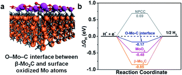
It is well-known that an active HER catalyst should have an adsorption free energy of H (ΔGH) close to zero. Nitrogen-doped-carbon-supported β-Mo2CNP composites have been shown to have very low ΔGH by DFT calculations.33,37 Accordingly, we carried out density functional theory (DFT) calculations to gain a more in-depth understanding of the role of the O–Mo–C interfaces in enhancing β-Mo2C@NPCC performance for HER. Since catalysis takes place on the exposed surfaces of the catalysts, we considered both the β-Mo2C and Mo–O moieties in β-Mo2C@NPCC as possible active sites for the evolution of H2. The structural model of the O–Mo–C interface is illustrated in Fig. S26† and was employed to calculate ΔGH for this material. In this model, the Mo atoms in the outermost layer of β-Mo2C are linked by oxygen atoms to create an O–Mo–C interface (Fig. 5a). The N/C molar ratio was chosen to match that obtained from the elemental analysis of β-Mo2C@NPCC. H atoms, generated from the combination of protons and electrons, adsorb on Mo sites. The ΔGH values calculated for the O–Mo–C interface, β-Mo2C and various other reference materials are summarized in Fig. 5b. It is noted that the HER catalytic activities of Mo2C are very facet-dependent.46 Here in our study, the (001) facet with Mo-termination was adopted to act as the active surface for the β-Mo2C nanoparticle, as indicated by previous studies.33,37 Compared with β-Mo2C, MoO3, and NPCC, the O–Mo–C interface offered the most optimal ΔGH value (−0.17 eV), i.e., a value close to zero. This helps to explain the excellent experimental HER performance of β-Mo2C@NPCC, which is inherently rich in O–Mo–C interfaces on the surface of the ultrafine β-Mo2C nanoparticles.
β-Mo2C@NPCC is an excellent catalyst for generating hydrogen from water by electrolysis in both acidic and basic electrolytes. This can be ascribed to: (i) the electrical conductivity, porosity and hollow morphology of the nitrogen-doped porous carbon capsules, which have excellent permeability and facilitate access of the substrates and electrons to the catalytic sites;33,37 (ii) firm attachment of the embedded ultrafine β-Mo2C nanoparticles to the carbon capsules to prevent β-Mo2C sintering or detachment; (iii) the presence of Mo–O atomic layers on the surface of the β-Mo2C nanoparticles, which provides a large area of exposed O–Mo–C active sites (well-defined O–Mo–C interfaces with ideal energetics for reduction of water to hydrogen).
Conclusions
In summary, we have developed an outstanding electrocatalyst system for HER, composed of ultrafine β-Mo2C nanoparticles embedded within N-doped carbon capsules, by carbonization of ZIF-8 nanocrystals coated with a molybdenum–tannic acid coordination polymer shell. Post synthetic air oxidation created O–Mo–C interfaces at the surface of the β-Mo2C nanoparticles which greatly benefitted hydrogen evolution. β-Mo2C@NPCC demonstrated a HER performance similar to Pt/C (20 wt% Pt) in both acidic and alkaline media. DFT calculations demonstrated that the O–Mo–C interfaces on the surface of the β-Mo2C nanoparticles underpinned the excellent HER activity of β-Mo2C@NPCC. The carbonization of MOF nanocrystals coated with a metal-containing tannic acid polymer appears to be a simple and scalable strategy towards novel earth-abundant element electrocatalysts for HER. Further, the results presented here should encourage the wider pursuit of ultrathin transition metal carbide-based catalysts as replacements for precious metal catalysts in water splitting and other applications.Experimental section
Synthesis of ZIF-8 nanocrystals
ZIF-8 nanocrystals were prepared using a literature method with a slight modification.47 In a typical synthesis, 2-methylimidazole (4.0 g) was dissolved in methanol (MeOH, 60 mL) to form a clear solution. Zn(NO3)2·6H2O (1.68 g) in MeOH (20 mL) was added into the above solution followed by vigorous stirring for 1 h. The mixture was then incubated at room temperature without stirring. After 24 h, the product was isolated as a white powder by centrifugation and washed several times with deionized water and MeOH, and finally dried overnight under vacuum.Synthesis of ZIF-8@K–TA composite
A ZIF-8@K–TA composite was prepared following our previously reported procedure.34 In a typical synthesis, ZIF-8 nanocrystals (200 mg) were dispersed in 10 mL of deionized water. Then, a tannic acid solution (3 mL, 24 mM) was prepared, with the pH subsequently adjusted to 8 by the addition of aqueous KOH. Subsequently, the suspension of the ZIF-8 nanocrystals was added to the tannic acid solution. After stirring for 5 min, the ZIF-8@K–TA product was collected by centrifugation, washed several times with deionized water and methanol, and dried under vacuum.Synthesis of ZIF-8@Mo–TA composite
In a typical synthesis, ZIF-8@K–TA (200 mg) was soaked in a methanolic solution (100 mL) of molybdenum acetate dimer [Mo2(OAc)4] (50 mg). After stirring for 5 h, the ZIF-8@Mo–TA solid was collected by centrifugation, washed several times with methanol, and dried overnight under vacuum.Synthesis of β-Mo2C@NPCC
In a typical synthesis, ZIF-8@Mo–TA was transferred into a ceramic crucible, placed in a furnace under a dry nitrogen flow, and heated from room temperature to 950 °C over a period of 15 h. After reaching the target temperature, the sample was heated at 950 °C for a further 5 h, then cooled to room temperature and left in the air to give β-Mo2C@NPCC.Author contributions
H. Y. and S. M. conceived the research. H. Y. synthesized samples. H. Y., X. W, W. Z., and G. V. performed the material characterizations. X. C., S. J. B., T. N., and H. T. performed TEM, STEM, and atomic resolution HAADF-STEM characterizations. G. H. and D. J. performed the DFT calculations. W. T. C. and G. I. N. W. performed XAS and XPS characterizations. H. Y., P. E. K., S. G. T., X. W. and S. M. wrote the manuscript. All authors contributed to the discussion.Conflicts of interest
The authors declare no competing financial interest.Acknowledgements
We gratefully acknowledge the financial support from the North China Electric Power University, the Ministry of Business, Innovation and Employment for a Catalyst Fund grant (MAUX 1609), and the University of South Florida. DFT calculations were sponsored by the US Department of Energy, Office of Science, Office of Basic Energy Sciences, Chemical Sciences, Geosciences, and Biosciences Division and used resources of the National Energy Research Scientific Computing Center, a DOE Office of Science User Facility supported by the Office of Science of the US Department of Energy under contract no. DE-AC02-05CH11231. We also acknowledge the Australian Nuclear Science and Technology Organization (ANSTO) for in-kind funding support to conduct experiments at the Australian Synchrotron.Notes and references
- M. S. Dresselhaus and I. L. Thomas, Nature, 2001, 414, 332–337 CrossRef CAS PubMed.
- W. Sheng, M. Myint, J. G. Chen and Y. Yan, Energy Environ. Sci., 2013, 6, 1509–1512 RSC.
- J. H. Barber and B. E. Conway, J. Electroanal. Chem., 1999, 461, 80–89 CrossRef CAS.
- Y. Shi and B. Zhang, Chem. Soc. Rev., 2016, 45, 1781 RSC.
- C. G. Morales-Guio, L.-A. Stern and X. Hu, Chem. Soc. Rev., 2014, 43, 6555–6569 RSC.
- X. Fan, Z. Peng, R. Ye, H. Zhou and X. Guo, ACS Nano, 2015, 9, 7407–7418 CrossRef CAS PubMed.
- H. Fan, H. Yu, Y. Zhang, Y. Zheng, Y. Luo, Z. Dai, B. Li, Y. Zong and Q. Yan, Angew. Chem., Int. Ed., 2017, 56, 12566–12570 CrossRef CAS PubMed.
- S. T. Hunt, T. Nimmanwudipong and Y. Roman-Leshkov, Angew. Chem., Int. Ed., 2014, 53, 5131–5136 CAS.
- Q. Gong, Y. Wang, Q. Hu, J. Zhou, R. Feng, P. N. Duchesne, P. Zhang, F. Chen, N. Han, Y. Li, C. Jin, Y. Li and S. T. Lee, Nat. Commun., 2016, 7, 13216 CrossRef CAS PubMed.
- M. Miao, J. Pan, T. He, Y. Yan, B. Y. Xia and X. Wang, Chem, 2017, 23, 10947–10961 CrossRef CAS PubMed.
- Y. Zhong, X. Xia, F. Shi, J. Zhan, J. Tu and H. J. Fan, Adv. Sci., 2016, 3, 1500286 CrossRef PubMed.
- R. Michalsky, Y.-J. Zhang and A. A. Peterson, ACS Catal., 2014, 4, 1274–1278 CrossRef CAS.
- W.-F. Chen, J. T. Muckerman and E. Fujita, Chem. Commun., 2013, 49, 8896–8909 RSC.
- H. Yan, Y. Xie, Y. Jiao, A. Wu, C. Tian, X. Zhang, L. Wang and H. Fu, Adv. Mater., 2018, 30, 1704156 CrossRef.
- S. Li, C. Cheng, A. Sagaltchik, P. Pachfule, C. Zhao and A. Thomas, Adv. Funct. Mater., 2019, 29, 1807419 CrossRef.
- H. Lin, Z. Shi, S. He, X. Yu, S. Wang, Q. Gao and Y. Tang, Chem. Sci., 2016, 7, 3399–3405 RSC.
- Z. Y. Yu, Y. Duan, M. R. Gao, C. C. Lang, Y. R. Zheng and S. H. Yu, Chem. Sci., 2017, 8, 968–973 RSC.
- K. Xiong, L. Li, L. Zhang, W. Ding, L. Peng, Y. Wang, S. Chen, S. Tan and Z. Wei, J. Mater. Chem. A, 2015, 3, 1863–1867 RSC.
- J. Zhang, X. Meng, J. Zhao and Z. Zhu, ChemCatChem, 2014, 6, 2059–2064 CrossRef CAS.
- P. Xiao, X. Ge, H. Wang, Z. Liu, A. Fisher and X. Wang, Adv. Funct. Mater., 2015, 25, 1520–1526 CrossRef CAS.
- M. Li, Y. Zhu, H. Wang, C. Wang, N. Pinna and X. Lu, Adv. Eng. Mater., 2019, 9, 1803185 Search PubMed.
- Y. Liu, B. Huang and Z. Xie, Appl. Surf. Sci., 2018, 427, 693–701 CrossRef CAS.
- L. He, W. Zhang, Q. Mo, W. Huang, L. Yang and Q. Gao, Angew. Chem., Int. Ed., 2020, 59, 3544–3548 CrossRef CAS PubMed.
- Z. Chen, D. Cummins, B. N. Reinecke, E. Clark, M. K. Sunkara and T. F. Jaramillo, Nano Lett., 2011, 11, 4168–4175 CrossRef CAS PubMed.
- I. Roger, R. Moca, H. N. Miras, K. G. Crawford, D. A. J. Moran, A. Y. Ganin and M. D. Symes, J. Mater. Chem. A, 2017, 5, 1472–1480 RSC.
- I. S. Amiinu, Z. Pu, X. Liu, K. A. Owusu, H. G. R. Monestel, F. O. Boakye, H. Zhang and S. Mu, Adv. Funct. Mater., 2017, 27, 1702300 CrossRef.
- Z. Shi, B. Gao, Q. Mo, Z.-J. Shao, K. Nie, B. Liu, H. Zhang, Y. Wang, Y. Zhang, Q. Gao, X. Sun, X.-M. Cao, P. Hu and Y. Tang, ChemNanoMat, 2018, 4, 194–202 CrossRef CAS.
- F. Davodi, E. Muhlhausen, D. Settipani, E. L. Rautama, A. P. Honkanen, S. Huotari, G. Marzun, P. Taskinen and T. Kallio, J. Colloid Interface Sci., 2019, 556, 180–192 CrossRef CAS PubMed.
- Y. Tian, L. Xu, J. Qian, J. Bao, C. Yan, H. Li, H. Li and S. Zhang, Carbon, 2019, 146, 763–771 CrossRef CAS.
- H. Wei, Q. Xi, X. Chen, D. Guo, F. Ding, Z. Yang, S. Wang, J. Li and S. Huang, Adv. Sci., 2018, 5, 1700733 CrossRef.
- Y. Huang, J. Hu, H. Xu, W. Bian, J. Ge, D. Zang, D. Cheng, Y. Lv, C. Zhang, J. Gu and Y. Wei, Adv. Eng. Mater., 2018, 8, 1800789 Search PubMed.
- L. Chen, H. Jiang, H. Jiang, H. Zhang, S. Guo, Y. Hu and C. Li, Adv. Eng. Mater., 2017, 7, 1602782 Search PubMed.
- J. S. Li, Y. Wang, C. H. Liu, S. L. Li, Y. G. Wang, L. Z. Dong, Z. H. Dai, Y. F. Li and Y. Q. Lan, Nat. Commun., 2016, 7, 11204 CrossRef CAS PubMed.
- H. Yang, S. J. Bradley, A. Chan, G. I. Waterhouse, T. Nann, P. E. Kruger and S. G. Telfer, J. Am. Chem. Soc., 2016, 138, 11872–11881 CrossRef CAS PubMed.
- H. Yang, S. J. Bradley, X. Wu, A. Chan, G. I. N. Waterhouse, T. Nann, J. Zhang, P. E. Kruger, S. Ma and S. G. Telfer, ACS Nano, 2018, 12, 4594–4604 CrossRef CAS PubMed.
- F. X. Ma, H. B. Wu, B. Y. Xia, C. Y. Xu and X. W. Lou, Angew. Chem., Int. Ed., 2015, 54, 15395–15399 CrossRef CAS PubMed.
- Y. Liu, G. Yu, G.-D. Li, Y. Sun, T. Asefa, W. Chen and X. Zou, Angew. Chem., Int. Ed., 2015, 54, 10752–10757 CrossRef CAS PubMed.
- Y. Y. Chen, Y. Zhang, W. J. Jiang, X. Zhang, Z. Dai, L. J. Wan and J. S. Hu, ACS Nano, 2016, 10, 8851–8860 CrossRef CAS PubMed.
- Y. Zheng, Y. Jiao, Y. Zhu, L. H. Li, Y. Han, Y. Chen, A. Du, M. Jaroniec and S. Z. Qiao, Nat. Commun., 2014, 5, 3783 CrossRef PubMed.
- T. Ressler, J. Catal., 2002, 210, 67–83 CrossRef CAS.
- J.-Z. Zhang, M. A. Long and R. F. Howe, Catal. Today, 1998, 44, 293–300 CrossRef CAS.
- S. Liu, L. Wang, R. Ohnishi and M. Ichikawa, J. Catal., 1999, 181, 175–188 CrossRef CAS.
- G. Zhao, K. Rui, S. X. Dou and W. Sun, Adv. Funct. Mater., 2018, 28, 1803291 CrossRef.
- Q. Gao, W. Zhang, Z. Shi, L. Yang and Y. Tang, Adv. Mater., 2019, 31, 1802880 CrossRef PubMed.
- H. Li, X. Jia, Q. Zhang and X. Wang, Chem, 2018, 1510–1537 CrossRef CAS PubMed.
- T. T. Yang and W. A. Saidi, Nanoscale, 2017, 9, 3252–3260 RSC.
- S. R. Venna, J. B. Jasinski and M. A. Carreon, J. Am. Chem. Soc., 2010, 132, 18030–18033 CrossRef CAS PubMed.
Footnote |
| † Electronic supplementary information (ESI) available. See DOI: 10.1039/d0sc00427h |
| This journal is © The Royal Society of Chemistry 2020 |

