 Open Access Article
Crystallographic facet selective HER catalysis: exemplified in FeP and NiP2 single crystals†
Bryan
Owens-Baird
 ab,
Juliana P. S.
Sousa
c,
Yasmine
Ziouani
c,
Dmitri Y.
Petrovykh
 c,
Nikolai A.
Zarkevich
 b,
Duane D.
Johnson
 bd,
Yury V.
Kolen'ko
 *c and
Kirill
Kovnir
 *ab
*ab
aDepartment of Chemistry, Iowa State University, Ames, IA 50011, USA. E-mail: kovnir@iastate.edu
bAmes Laboratory, U.S. Department of Energy, Ames, IA 50011, USA
cNanochemistry Research Group, International Iberian Nanotechnology Laboratory, Braga 4715-330, Portugal
dDepartment of Materials Science & Engineering, Iowa State University, Ames, IA 50011, USA
First published on 20th April 2020
Abstract
How the crystal structures of ordered transition-metal phosphide catalysts affect the hydrogen-evolution reaction (HER) is investigated by measuring the anisotropic catalytic activities of selected crystallographic facets on large (mm-sized) single crystals of iron-phosphide (FeP) and monoclinic nickel-diphosphide (m-NiP2). We find that different crystallographic facets exhibit distinct HER activities, in contrast to a commonly held assumption of severe surface restructuring during catalytic activity. Moreover, density-functional-theory-based computational studies show that the observed facet activity correlates well with the H-binding energy to P atoms on specific surface terminations. Direction dependent catalytic properties of two different phosphides with different transition metals, crystal structures, and electronic properties (FeP is a metal, while m-NiP2 is a semiconductor) suggests that the anisotropy of catalytic properties is a common trend for HER phosphide catalysts. This realization opens an additional rational design for highly efficient HER phosphide catalysts, through the growth of nanocrystals with specific exposed facets. Furthermore, the agreement between theory and experimental trends indicates that screening using DFT methods can accelerate the identification of desirable facets, especially for ternary or multinary compounds. The large single-crystal nature of the phosphide electrodes with well-defined surfaces allows for determination of the catalytically important double-layer capacitance of a flat surface, Cdl = 39(2) μF cm−2 for FeP, useful for an accurate calculation of the turnover frequency (TOF). X-ray photoelectron spectroscopy (XPS) studies of the catalytic crystals that were used show the formation of a thin oxide/phosphate overlayer, presumably ex situ due to air-exposure. This layer is easily removed for FeP, revealing a surface of pristine metal phosphide.
Introduction
In the past few decades, renewable energy sources, such as wind, solar, ocean wave, and geothermal, have gained popularity due to their reduced emission of greenhouse gases.1–3 Unfortunately, many of these energy sources are intermittent in nature and cannot provide uninterrupted power generation. Many storage solutions for such intermittent energy production have been presented to address this downtime, such as batteries, capacitors, gravitational storage, or chemical bonds, allowing for power storage and delivery as required.4 Of these suggestions, on-site production of H2 fuel is highly advantageous, as H2 is ultra-lightweight and offers the highest specific energy of any non-nuclear fuel.5 Additionally, the direct reaction of H2 and O2 results in only energy and environmentally benign H2O. The production of both H2 and O2 can be achieved through water electrolysis.Water electrolysis is the combination of two half reactions, the hydrogen evolution reaction (HER) and the oxygen evolution reaction (OER), occurring at the cathode and anode, respectively. Many catalyst materials can be used as electrodes for these processes, with their role being the reduction of the applied overpotential required to overcome slow reaction rates and charge-transfer limitations. Common and efficient catalysts used at both the cathode and anode are based on the elemental Pt or platinum-group metals (PGMs), identified as critical raw materials reflecting their limited availability and high price. Fortunately, 3d transition-metal phosphides (TMP) have been identified as replacements for PGMs as catalysis for HER and OER applications, possessing efficient performance, high-earth abundance, and lower costs.6–9
The majority of research surrounding TMPs for HER/OER applications has focused on Fe, Co, and Ni phosphides, with M2P, MP, and MP2 compositions.6–9 From analysis of published data, we have shown that for M2P systems, Ni2P exhibited the best HER performance; while among the MP systems, both FeP and CoP were superior HER catalysts.7 This analysis was conducted through literature survey of the overpotential required to drive 10 mA cm−2 (η10) and Tafel slopes (TS) for the catalysts. Reported data are quite scattered, for instance, for FeP one group reported η10 and TS values of 39 mV and 32 mV dec−1, respectively, while another group reported 240 mV and 67 mV dec−1.10,11 Thus, factors beyond structure and composition are at play, such as subtle surface effects of the nanomaterials.
Computational12,13 and experimental12,14–16 reports have shown specific crystallographic directions of materials can exhibit significantly different catalytic behaviors, such as the individual facets of the CoPS HER catalyst. Growth and exposure of inefficient catalytic surfaces (facets with specific Miller-indexed directions) could account for some (or most) of the discrepancies observed across the literature. Therefore, to gain a direct understanding of TMPs for HER applications, model systems must be employed to identify catalytically efficient crystallographic facets of individual TMPs and help with the future rational design and optimization of HER materials.
It is a common belief that the HER performance is highly dictated by structure of the surface and can be tuned by choice of metals used. It is still an open question whether surface restructuring under the reaction conditions is sensitive to the structure of the corresponding bulk phases. We have recently shown that the catalytic performance of two polymorphs of the same metal phosphide in powder form, NiP2, was drastically different in both HER and OER.17 Here, we address this issue by studying the catalytic activities of the different facets of the same material, either FeP or m-NiP2. Most studies conducted on TMPs for HER applications are focused on the reduction of the overpotential required to drive the catalyst. In this study, we did not concern ourselves with this reduction, but instead focused on the relative activity of the different crystal facets, thus directly probing the structural sensitivity of TMP towards HER. This method allows comparison of catalytic activities of multiple surfaces of prominent HER catalysts with differing crystallographic directions.
Here, the growth of mm-sized crystals of FeP and m-NiP2, catalytic properties of selected crystallographic facets, and the observed structural sensitivity toward HER in acidic conditions are presented. The model systems show clear evidence of crystallographic facet sensitivity in HER. Additionally, as the surface area of the crystal is known and measurable, we probed the catalytically active surface area for FeP through double-layered capacitance of flat surface measurements. The double-layered capacitance of a material, used in the calculation of catalytically active surface area and turnover frequency, is often assumed and not experimentally measured. Furthermore, the surface characteristics of the catalytically tested crystals were probed using high-resolution X-ray photoelectron spectroscopy, which show the formation of easily removable oxide/phosphate layers. Finally, we use the computationally derived H-binding energies on different surfaces of FeP as a simple indicator of catalytic activity of a specific facet, correlating with the observed behavior.
Materials and methods
Computational details
To assess the various bulk systems and facets for H-terminated surfaces to compare to experimental trends, along with the associated electronic-structure and enthalpy effects, we utilized spin-polarized density functional theory (DFT). In particular, structural and bonding energies were calculated using DFT as developed in the Vienna ab initio simulation package (VASP),18,19 utilizing projector augmented waves (PAW) basis,20,21 the PBE exchange-correlation functional,22 and a modified Broyden method23 for accelerated convergence. Brillouin-zone integrations were performed on a Monkhorst–Pack k-point mesh.24 For bulk FeP D2h-16 structure (Fig. S3†) with orthorhombic space group Pnma (No. 62), the atoms and cell vectors were fully relaxed at zero pressure using a conjugate-gradient algorithm (with settings IBRION = 2, ISIF = 3 in VASP). For bulk relaxations, a Γ-centered k-point mesh (16 × 24 × 16) was used, and a denser k-mesh (24 × 32 × 24) was used for calculating the density of states (DOS), applying a Gaussian smearing of 0.1 eV broadening to enhance convergence. For bulk FeP, the calculated equilibrium lattice constants for the orthorhombic cell are a = 5.152 Å, b = 3.046 Å, and c = 5.761 Å. The bulk DOS is provided in ESI (Fig. S4†).Surfaces with specific crystallographic termination were prepared by appropriate cuts of, for example, bulk FeP structure into a slab geometry, separated by ∼12 Å of vacuum, with a periodicity from 10 to 20 Å in each direction. We considered a sufficiently large periodic box in which the surface atoms do not interact with their periodic images (or with the next slab), permitting periodic boundary conditions and Monkhorst–Pack (Γ-centered) meshes to be used for computational efficiency and accuracy. The top few atomic layers near vacuum were relaxed, while atoms in the bottom two layers were fixed to bulk locations, which overall mimics the effects in an infinite bulk with a cleaved surface. The supercell volume and shape containing the slab in vacuum was then fixed. To compute binding energy, for example, a single H atom was attached to one of the symmetry-distinct atoms on the surface, as will be exemplified.
Chemicals
All chemicals were used as received. Fe powder (99.9%, Alfa Aesar), Ni powder (99.996%, Alfa Aesar), red P powder (99%, Alfa Aesar), Sn shot (99.8%, Alfa Aesar), Au wire (99.95%, 0.1 mm diameter, Alfa Aesar), and H2SO4 (96%, Fisher). Ultrapure water (18.2 MΩ cm−2, TOC < 3 ppb) was generated using a Milli-Q Advantage A10 system (Millipore).Crystal growth
Single crystals of FeP and m-NiP2 were grown via Sn-flux. Elements were loaded into a silica ampoule (total sample weight 50 g) in the M![[thin space (1/6-em)]](https://www.rsc.org/images/entities/char_2009.gif) :
:![[thin space (1/6-em)]](https://www.rsc.org/images/entities/char_2009.gif) P
P![[thin space (1/6-em)]](https://www.rsc.org/images/entities/char_2009.gif) :
:![[thin space (1/6-em)]](https://www.rsc.org/images/entities/char_2009.gif) Sn ratio of 1
Sn ratio of 1![[thin space (1/6-em)]](https://www.rsc.org/images/entities/char_2009.gif) :
:![[thin space (1/6-em)]](https://www.rsc.org/images/entities/char_2009.gif) 1
1![[thin space (1/6-em)]](https://www.rsc.org/images/entities/char_2009.gif) :
:![[thin space (1/6-em)]](https://www.rsc.org/images/entities/char_2009.gif) 50 for FeP and 1
50 for FeP and 1![[thin space (1/6-em)]](https://www.rsc.org/images/entities/char_2009.gif) :
:![[thin space (1/6-em)]](https://www.rsc.org/images/entities/char_2009.gif) 2
2![[thin space (1/6-em)]](https://www.rsc.org/images/entities/char_2009.gif) :
:![[thin space (1/6-em)]](https://www.rsc.org/images/entities/char_2009.gif) 50 for m-NiP2, evacuated, and flame sealed. The ampoule was heated from room-temperature to 1373 K over 17 h, annealed for 48 h, and cooled to 773 K over 120 h. At 773 K the ampoule was flipped and centrifuged to remove most of the molten tin. After centrifugation, the samples were treated with a 1
50 for m-NiP2, evacuated, and flame sealed. The ampoule was heated from room-temperature to 1373 K over 17 h, annealed for 48 h, and cooled to 773 K over 120 h. At 773 K the ampoule was flipped and centrifuged to remove most of the molten tin. After centrifugation, the samples were treated with a 1![[thin space (1/6-em)]](https://www.rsc.org/images/entities/char_2009.gif) :
:![[thin space (1/6-em)]](https://www.rsc.org/images/entities/char_2009.gif) 1 HCl
1 HCl![[thin space (1/6-em)]](https://www.rsc.org/images/entities/char_2009.gif) :
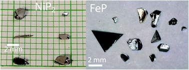
:![[thin space (1/6-em)]](https://www.rsc.org/images/entities/char_2009.gif) H2O solution for 5 h, filtered, and dried. Large shiny, silvery crystals were collected (Fig. 1).
H2O solution for 5 h, filtered, and dried. Large shiny, silvery crystals were collected (Fig. 1).
Crystal preparation for facet-selective catalysis
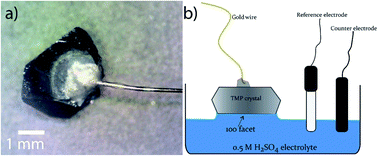
The facet-indexed crystals of FeP and m-NiP2 were attached to 0.1 mm diameter gold wires using conductive H20E epoxy (Epoxy Technology Inc.). These wires are attached opposite to the crystallographic facets that are to be studied. Once attached to the crystal, the assembly is placed in a vacuum oven and annealed at 150 °C under vacuum for 5 min before being cooled under vacuum. Once cooled, the crystal-epoxy joint is coated in a thin layer of super-glue to resist corrosion of the epoxy if exposed to H2SO4 solution (Fig. 2a). The crystal assemblies are robust and can be easily handled by users.Produced crystals were characterized by single-crystal X-ray diffraction and X-ray photoelectron spectroscopy. The HER catalytic activities of selected facets were measured in 0.5 M H2SO4 electrolyte. See ESI† for the details of characterization, catalytic tests, and computations.
Results
In the flux crystal growth, controllable nucleation and growth are hard to achieve,25 and spontaneous crystallization leads to growth of crystals of different shapes with different large facets (Fig. 1). For the current catalytic studies, we have selected several crystals with large facets, i.e., having surface areas of 0.5–2 mm2. Reproducibility of results was checked on the NiP2 crystals, with two different crystals grown from different flux reactions exhibit large [111] facets (vide infra). A controllable nucleation and growth can be achieved when other growth techniques are used, such as Bridgman–Stockbarger or Czochralski methods, however, high melting points of the target phosphides in combination with high vapor pressure of P at elevated temperatures makes metal phosphide challenging targets for both methods.FeP facet catalysis
Four crystals of FeP were chosen to test, each with a unique crystallographic facet and reasonably large surface area (0.5–2 mm2) of each facet. These facets correspond to the [010], [011], [101], and [111] crystallographic directions.As seen in Fig. 3 and Table 1, the HER activity does depend on the crystallographic direction that is tested. The facet corresponding to the [010] plane exhibited the highest performance, followed by the [101] and [111] facets that showed similar behavior, and finally the [011] facet displayed the worst activity. Separation of the activity becomes more pronounced at higher current densities (Table 1 and Fig. 3a) with the exception of the [101] and [111] facets, which show the same activity at high current densities. Additionally, calculated Tafel slopes of 75, 79, 84, and 89 mV dec−1 were quite similar to each other for all tested surfaces (Fig. S1†).
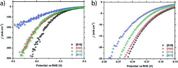 | ||
| Fig. 3 Cathodic polarization curves for the FeP [010], [101], [111], and [011] facets: (a) full plot and (b) enhanced region showing low current density range. | ||
| Facet index | η 10 (−10 mA cm−2) | η 20 (−20 mA cm−2) | η 100 (−100 mA cm−2) |
|---|---|---|---|
| FeP crystals | |||
| [010] | −209 mV | −240 mV | −320 mV |
| [101] | −212 mV | −245 mV | −343 mV |
| [111] | −225 mV | −256 mV | −349 mV |
| [011] | −241 mV | −279 mV | −391 mV |
![[thin space (1/6-em)]](https://www.rsc.org/images/entities/char_2009.gif) |
|||
| m-NiP 2 crystals | |||
| [100] | −231 mV | −257 mV | −345 mV |
| [121] | −264 mV | −303 mV | −383 mV |
| [101] | −278 mV | −313 mV | −389 mV |
| [111] (crystal 1) | −322 mV | −350 mV | −445 mV |
| [111] (crystal 2) | −325 mV | −353 mV | −453 mV |
m-NiP2 facet catalysis
Similarly, five crystals of m-NiP2 were chosen for examination and five facets were tested: [100], [121], [101], [111]1, and [111]2. Two facets of [111] were studied to test the consistency of the method. Like FeP, a clear structural sensitivity toward the HER process is observed for m-NiP2 based on crystallographic termination (Fig. 4 and Table 1). The [100] direction shows the highest activity, followed by [121] and [101], and finally the [111] directions. Performance in the [111] facet was nominally the same for the two tested facets, only slightly deviating at higher current densities. The current is normalized to surface area tested, implying that small errors in measurement of the surface area would have larger effects at higher current densities, possibly leading the deviation seen in the [111] facet performances. Nevertheless, both measured [111] facets exhibit the same Tafel slope of 89 mV dec−1 (Fig. S2†). Similar Tafel slope was observed for [100] m-NiP2 facet, while [101] and [121] facets exhibit larger Tafel slopes of 109 and 115 mV dec−1, respectively.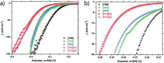 | ||
| Fig. 4 Cathodic polarization curves for the m-NiP2 [100], [121], [101], [111]1, and [111]2 facets: (a) full plot and (b) a zoomed region showing low current density range. | ||
Double-layer capacitance of FeP
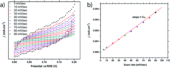
Double-layer capacitance of flat surface (Cdl) of a material is crucially important, as it is needed to calculate the electrochemical active surface area (ECSA) and turnover of the frequency (TOF). Oftentimes, the Cdl of a material is simply assumed based on previous reports that show typical Cdl values fall within the range of 20–60 μF cm−2.26–29 To accurately determine this value, the true surface area must be known, making this determination difficult for nanomaterials. As we had sizable single crystals of FeP with an easily measurable surface area, the Cdl value for this prominent electrocatalyst was probed.To elucidate the Cdl value, cyclic voltammetry (CV) was performed using various scan rates that ranged between 5 mV sec−1 and 90 mV sec−1. The potential range used was chosen where no faradaic processes were observed (0–0.2 VRHE). As seen in Fig. 5a, as the scan rate increases, the hysteresis loop of the CV curve widens due to charging effects. For each scan rate, ten CV curves were collected and the hysteresis gap at 0.1 V was measured, averaged, and halved. These values were plotted versus the scan rate (Fig. 5b) and the Cdl can be extracted from the linear fit. This process was performed on three separate FeP crystals fully immersed into the solution, resulting in Cdl values of 42, 38, and 37 μF cm−2. The average of 39(2) μF cm−2 is well within the previously predicted range. Difference in Cdl values from crystal to crystal could be due to surface area measurement errors or due to a structural sensitivity of Cdl. Double-layer capacitance studies of m-NiP2 were not successful, possibly due to semiconducting nature of the material.
Computational results for surfaces
We used as-prepared surfaces with slab geometry for specific FeP crystallographic terminations (Fig. 6) compared to the bulk. To compute DFT binding energies, a single H was attached (Fig. 6) to one of the symmetry-distinct atoms on the surface (Table 2). The bulk DOS (Fig. S4†) shows that P 3p-states hybridize with Fe 3d-states well below the Fermi energy (−3.5 to −4.5 eV), stabilizing the structure. Hence, when a surface is formed, P and Fe will re-structure the surface layer to accommodate the lost electrons, or, P (typically) will be prominent in bonding with an adsorbate available. Notably, on a surface, an adsorbent may form bonds with more than one atom, as seen on some surfaces (Fig. 6).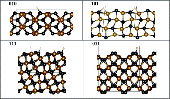 | ||
| Fig. 6 FeP fully relaxed surfaces with minimal-energy bonding to H. Atoms are denoted by spheres for Fe (orange), P (black), and H (white), while the unit cell is shown by grey lines. Notice that ideal (010), (111) and (011) surfaces are not flat, as they exhibit P “edge” features where H bonding is favored, contrasting to the ideal (101) surface. The fully relaxed ideal (101) flat surface is less stable and may lead to step formation, see Table S1 and Fig. S5.† All structural images were generated using VESTA software.40 | ||
Importantly for the present discussion, Wang and Johnson generalized the “d-band” theory for adsorption energies at surfaces to ordered intermetallic compounds with line compositions, i.e., narrow homogeneity range.30 They showed that there is a linear correlation between adsorption energies for HER and OER (actually any atom/molecule: H, N, O, CO, etc.) and the specific d-orbital energy participating in the adsorption on a given crystallographic facet. Surfaces with similar symmetries have the same orbitals participating and, as such, a Brønsted–Evans–Polanyi relation is thus different for each symmetry-distinct adsorption site, similar to that found for molecular adsorption on simple d-band metals.31 In addition, a stepped surface (i.e., a terrace with particular index) will typically be lower in adsorption, as step edges are more active (have stronger adsorption) than the pristine facet surface.31 Interestingly, if the kinetics follows the same linear correlation, then so-called “volcano plots” for reactivity follows to guide the best reactivity.32 So, the expected correlation suggests that the operative binding energy should mirror the reactivity (i.e., the overpotential) on specific surface facet (indexed surfaces).
Hence, we assess relative adsorption of H on FeP-terminated surfaces. From Table 2, it is evident that the P–H binding energy is larger than that of Fe–H on [010], [111], [011] facets, so that H prefer to sit on P rather than on Fe, similar to observation for the Ni–P catalysts.33–35 In particular, the P–H bond energy shows a specific order (smallest-to-largest) of [011], [111], and [010]. With this result, we anticipate that S or Se modification of P sublattices strongly affects the activity, and a similar effect was observed in experiments for Ni- and Co-containing systems.36,37 Computed energies indicate that surfaces that have different P–H bonding are expected to exhibit different relative reactivity. And, this may translate into non-perfect (not flat) surfaces, i.e., the structure of the layer may not critically matter. Indeed, amongst surfaces considered in experiment, only [101] has an ideal (flat) surface to consider, which is unstable to a P–H termination (Fig. S5†) and forms a P–H–Fe bond, while all the others show a prominent “step-like” surface configuration (Fig. 6) permitting a dominant P–H bond. Flat [101] surface has two possible terminations (Fig. S5a and b†), one of which (termination 1) is more stable than the other (termination 2) (Table S1†). The steps on the [101] (termination 1) surface cost energy, but this energy cost is moderate, hence the steps are possible. [201] given in Table S1† can be viewed as an example of [101] surface with periodic steps.
Notably, we compare the order of the measured HER activity on each facet (best-to-worst in Table 1) with that of P–H bonding in Table 2, finding they directly correlate. We hypothesize that for any ordered phosphide, like FeP, the derived linear correlation between adsorbate energy and energy of d-orbital that is operative in the adsorbate bonding permits computational screening of phosphide surfaces as a direct guide to experiment for new HER catalysts. Moreover, such line-compounds and their facets can be assessed and tuned for specific reactions and applications.38,39
The effect of the hydrogen coverage was studied on the example of FeP [010] and [011] surfaces (Fig. S6†). A small variation of the adsorption energy with coverage was observed, however, at each studied coverage a much higher difference in adsorption energies between H adsorption energy on [010] and [011] termination was preserved (Fig. S6†).
Surface composition
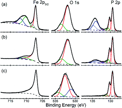
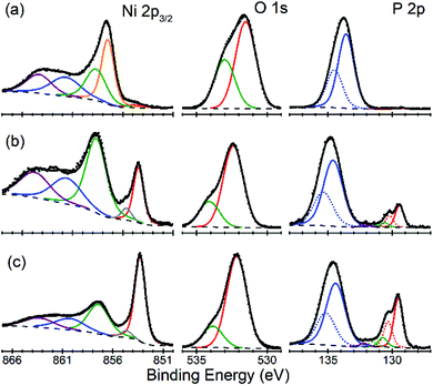
There is an open question whether in situ restructuring of the phosphide surface and oxidation to phosphate occurs during the HER reaction. Arguments for this assumption are the observations of the oxide/phosphate layers on the surface of HER phosphide catalysts after reaction is complete. However, highly reductive potentials and presence of the H species on the surface are strong counterarguments. Oxidation may occur when the freshly reduced surface of the catalyst is exposed to ambient conditions. An exact answer to this question requires in situ surface studies, which are challenging for HER conditions. As the first step towards such studies, we characterized the [010] (FeP) and [101] (m-NiP2) crystal surfaces after HER catalytic tests by means of X-ray photoelectron spectroscopy (XPS) (Fig. 7 and 8).Surfaces of both catalysts, FeP and m-NiP2, after HER reaction showed indications of oxidation (Fig. 7a and 8a). To probe the thickness of the oxide layer, a gentle sputter cleaning was attempted using Ar clusters, which are typically effective at removing surface contamination layers without significantly damaging the underlying solid inorganic material.41 The sputter cleaning revealed a qualitative difference between the oxidized surface layers on the two crystals. For the FeP sample, the etch rate was consistent (Fig. S7†) until the complete removal of the oxidized surface layer (Fig. 7c). In contrast, for the m-NiP2 sample, the etch rate dramatically slowed down after removing the topmost ca. 5 nm, to the extent that the same number of subsequent etching cycles removed only ca. 1 nm of the overlayer (Fig. S8†). As more aggressive etching conditions would modify surface composition and BEs,42 the depth profiling was stopped at that point, corresponding to a m-NiP2 crystal surface with ca. 3 nm of an oxidized overlayer (Fig. 8c).
For FeP, the strongest indications of reaching a clean crystalline surface after sputter cleaning are provided by the qualitative changes in all the elemental spectra from top to bottom in Fig. 7. The Fe 2p3/2 spectrum is simplified to a single component at BE = 707.0 eV, in agreement with BE values previously reported for FeP powder samples.43,44 The pronounced asymmetry of the Fe 2p3/2 spectrum in Fig. 7c is typically characteristic of pure metals, however, for FeP the BE and line shape nearly identical to those of Fe metal are well established and have been attributed to the details of the electronic structure of crystalline FeP.43 The P 2p spectrum in Fig. 7c is in agreement with the literature reports for FeP powders.43,44 We note, however, that because some sputter cleaning has been involved in all cases, the exact BEs reported here and in the literature likely correspond to a FeP crystal surface with some degree of amorphization: for example, both BEs and stoichiometry significantly shifted for a model Ni2P(0001) single-crystal surface after it was annealed to recover long-range ordering.42
The evolution of the Fe![[thin space (1/6-em)]](https://www.rsc.org/images/entities/char_2009.gif) :
:![[thin space (1/6-em)]](https://www.rsc.org/images/entities/char_2009.gif) P ratio (based only on the intensities of the phosphide Fe 2p and P 2p components, color-coded red in Fig. 7) during depth profiling suggests that even the soft etching by Ar clusters modified the surface composition. Specifically, the ratio of “phosphide” Fe
P ratio (based only on the intensities of the phosphide Fe 2p and P 2p components, color-coded red in Fig. 7) during depth profiling suggests that even the soft etching by Ar clusters modified the surface composition. Specifically, the ratio of “phosphide” Fe![[thin space (1/6-em)]](https://www.rsc.org/images/entities/char_2009.gif) :
:![[thin space (1/6-em)]](https://www.rsc.org/images/entities/char_2009.gif) P changed from ca. 1
P changed from ca. 1![[thin space (1/6-em)]](https://www.rsc.org/images/entities/char_2009.gif) :
:![[thin space (1/6-em)]](https://www.rsc.org/images/entities/char_2009.gif) 2 on the unmodified samples after HER treatment, to ca. 1
2 on the unmodified samples after HER treatment, to ca. 1![[thin space (1/6-em)]](https://www.rsc.org/images/entities/char_2009.gif) :
:![[thin space (1/6-em)]](https://www.rsc.org/images/entities/char_2009.gif) 1 in the middle of the profile, to ca. 1
1 in the middle of the profile, to ca. 1![[thin space (1/6-em)]](https://www.rsc.org/images/entities/char_2009.gif) :
:![[thin space (1/6-em)]](https://www.rsc.org/images/entities/char_2009.gif) 0.7 upon removal of all the phosphate components in Fig. 7c. The Fe-rich final composition could be produced by a number of effects, such as surface roughness and preferential sputtering, which are difficult to identify, because the nearly identical spectral signatures would not allow even to distinguish any accumulation of metallic Fe during the FeP sputtering. Intriguingly, the previous measurements on FeP powders reported reaching a 1
0.7 upon removal of all the phosphate components in Fig. 7c. The Fe-rich final composition could be produced by a number of effects, such as surface roughness and preferential sputtering, which are difficult to identify, because the nearly identical spectral signatures would not allow even to distinguish any accumulation of metallic Fe during the FeP sputtering. Intriguingly, the previous measurements on FeP powders reported reaching a 1![[thin space (1/6-em)]](https://www.rsc.org/images/entities/char_2009.gif) :
:![[thin space (1/6-em)]](https://www.rsc.org/images/entities/char_2009.gif) 1 stoichiometry after the more aggressive monoatomic Ar+ etching,43 so the exact nature of the FeP surface modification by sputter cleaning remains ambiguous.
1 stoichiometry after the more aggressive monoatomic Ar+ etching,43 so the exact nature of the FeP surface modification by sputter cleaning remains ambiguous.
For m-NiP2 sample after sputter cleaning (Fig. 8c), the phosphide Ni 2p3/2 and P 2p3/2 components are, respectively, at BEs of 853.3 and 129.5 eV, in excellent agreement with the values characteristic of the monoclinic m-NiP2 crystal structure.17 The qualitatively different spectra (in terms of line shapes and BEs) of the as-prepared m-NiP2 sample (Fig. 8a) are also consistent with the change of the sputtering rate after removal of the topmost ca. 5 nm of the oxidized overlayer (Fig. 8), as that part of the overlayer indeed appears to be compositionally different, likely a different mixture of Ni phosphates and hydroxides, based on the Ni 2p3/2 components.45 The more difficult to remove ca. 5 nm layer on top of the m-NiP2 single-crystal material is compositionally similar to the oxidation layers on as-prepared polycrystalline17 and nanostructured Ni phosphide catalysts,45,46 consistent with the previous interpretation of the Ni 2p3/2 component at BE of 857.5 ± 0.2 eV as primarily Ni phosphate. Finally, the difficulty in removing the phosphate overlayer from m-NiP2, highlights the apparently significant effect of the specific transition metal and bulk stoichiometry on the properties of the oxidized overlayers.
Discussion
The significant variation of catalytic activity for different facets on noble metal nano- and micro-crystals is well known in catalytic science. For the abundant transition metals such as Mn, Fe, Co, Ni, and Mo, an HER catalyst is not a single metal but a binary compound with non-metal elements (P, S, B) which brings strong chemical bonding and resulting chemical resistance.12,36,37,47–50 Moreover, metal atoms arrangement and band structure of the binary material are significantly different from those for elemental metals. Recent experimental and computational studies of crystals of Mo borides show that selected surfaces exhibit significantly higher HER activity, such as graphene-like boron-rich surfaces.47–50 While borides are known for high chemical inertness, in the field of transition-metal phosphide HER catalysts, it is commonly assumed that the surface of the catalysts is restructured during the reaction as a result of the applied bias potential and chemical potential of protons in solution. Evidence for this is the observed ex situ surface oxidation after potential cycling.7 As such, the important question remains whether the structure of bulk phosphide catalysts really matter, or if it is sufficient to supply the surface with a proper ratio of M/P elements and the restructuring will occur in situ. Reported properties for nano-structured catalysts are too scattered to provide a definitive answer. We have recently shown by studying the properties of two polymorphs of NiP2 that the structure of bulk phases has an impact on the catalytic properties of the corresponding phosphide.17 One possible explanation is that the monoclinic polymorph of NiP2 is a semiconductor, while cubic one has metallic properties, which might be sufficient to explain the observed difference in reactivity instead of their bulk crystal structures.In this current study, we investigated the electrocatalytic activity of the same bulk material, FeP or m-NiP2 single crystals. The only condition varied is the facet of the crystal that was exposed to the electrolyte. A clear dependence of the HER performance on the facet exposed was observed for both phosphides (Fig. 3 and 4) indicating that this is a common trend, rather than exception. Additionally, to test the reproducibility of the facet dependence, we measured two m-NiP2 [111] facets on two different crystals and show the identical performance within the accuracy of the experiments. Moreover, we have theoretically shown, from a more general adsorption analysis, that the facet activity correlates well with the computed H adsorption energy on P sites. Thus, the observed trends of the facet activity of transition-metal phosphides show that the underlying bulk structure, as well as specific surface termination, play an important role in the performance of HER electrocatalysts. This justifies computational screening of electrocatalytic activity based on bulk crystal structure of phosphides.
Single crystals have well-defined surfaces and are free from the contamination typical for nanostructured HER electrodes (such as binder or conductive additives), which allowed us to estimate double-layer capacitance of flat surface for FeP and characterize surface of the phosphide catalysts after reaction. Based on our computational observations, one can assume that P–H bonds, similar to those in phosphine PH3, dominate the surface of the phosphide catalyst under reaction condition, i.e., applied reducing bias. Phosphines are prone to oxidation under exposure to ambient conditions, which might be a source of the observed oxide/phosphate layers. Mild sputtering was sufficient to remove ca. 3nm of the oxide/phosphate layers for FeP, revealing a pristine FeP surface (Fig. 7c). XPS indicates the surface enrichment of the used FeP catalysts with P which was removed by sputtering. The oxide/phosphate layer was thicker for m-NiP2, which has intrinsically higher P content and higher chances for P-enrichment of the surface. Thus, the surface data obtained in this work can be explained without involving the formation of the metal oxide/phosphate during the HER, but rather after the reaction. To achieve a final answer on the composition and oxidation state of metal and P during HER an in situ experiments on the selected single crystals are necessary, which are currently under development.
Conclusion
Large mm-sized crystals of FeP and m-NiP2 were grown and crystallographically indexed. Individual crystal facets were tested for their HER catalytic activity, showing a facet-dependent activity for both types of phosphides. This difference becomes more apparent at high overpotentials. For FeP, decreasing activity of facets was found as: [010] > [101] > [111] > [011]; while for m-NiP2 the observed trend was: [100] > [121] > [101] > [111]. Validity of these trends was checked using two separate m-NiP2 crystals with exposed [111] facets, both showing near identical performance. Additionally, electrocatalytically important double-layer capacitance of flat surface, Cdl, measurements were performed on crystals of FeP, resulting in an average Cdl value of 39(2) μF cm−2.DFT calculations examined the effect of H bonding on experimentally exposed surfaces of FeP. Based on a predicted correlation for facet-specific, orbital-dependent adsorption, the H-binding energies on the relaxed FeP surfaces show a similar trend to the experimentally measured results, with [010] having the greatest binding energy and [011] the smallest. The greatest binding energies was found to be H adsorb predominantly on P sites, similar to computational reports for Ni and Co phosphides.
XPS was used to determine the surface characteristics of the catalytically tested crystals. These measurements showed thin oxide layers present on the surface of 3 and 5 nm for FeP and m-NiP2 crystals, respectively. The BEs and line shapes of the spectra collected for the bulk phases agree well with previously reported XPS data.
As the catalytic behaviors of FeP and m-NiP2 are shown to be directionally dependent, the anisotropic study of other prominent catalysts is prudent. This knowledge could lead to the rational design of highly efficient nano-catalysts with specifically grown facets to boost activity. Furthermore, the good agreement of the theory and experimental trends indicates that screening using DFT methods may accelerate the identification of desirable facet, especially for ternary or more complex compounds, where the original structure of metal phosphide is perturbed. Within the realm of solid-state chemistry, there are numerous ternary phosphide compounds, where the transition-metal 3d-orbital filling, local P coordination, and number of states at the Fermi energy can be tuned in a wide range allowing for novel HER catalysts. Coupled with computational screening, an integrated computational/experimental research should result in a novel HER catalysts with improved performance. Single crystals of phosphides are also suitable model systems for the in situ studies of the catalysts surface, finally answering how much of a role oxides play in the HER activity of phosphides.
Conflicts of interest
Authors declare no conflict of interests.Acknowledgements
Synthesis and facet indexing performed at Iowa State University are supported by startup funds. B. O. B. acknowledges partial support from the Center for Catalysis (CCAT) at Iowa State University. The materials theory at Ames Laboratory were supported by the U.S. Department of Energy (DOE), Office of Science, Basic Energy Sciences, Materials Science and Engineering Division. Ames Laboratory is operated for the U.S. DOE by Iowa State University under Contract No. DE-AC02-07CH11358. This work was partially supported by the European Union's Horizon 2020 research and innovation program through the CritCat Project under Grant Agreement No. 686053.References
- J. H. Montoya, L. C. Seitz, P. Chakthranont, A. Vojvodic, T. F. Jaramillo and J. K. Nørskov, Materials for solar fuels and chemicals, Nat. Mater., 2016, 16, 70 CrossRef PubMed.
- R. Schlögl, Sustainable Energy Systems: The Strategic Role of Chemical Energy Conversion, Top. Catal., 2016, 59(8), 772–786 CrossRef.
- Z. W. Seh, J. Kibsgaard, C. F. Dickens, I. Chorkendorff, J. K. Nørskov and T. F. Jaramillo, Combining theory and experiment in electrocatalysis: insights into materials design, Science, 2017, 355(6321), 4998 CrossRef PubMed.
- T. M. I. Mahlia, T. J. Saktisahdan, A. Jannifar, M. H. Hasan and H. S. C. Matseelar, A review of available methods and development on energy storage; technology update, Renewable Sustainable Energy Rev., 2014, 33, 532–545 CrossRef.
- N. S. Lewis and D. G. Nocera, Powering the planet: chemical challenges in solar energy utilization, Proc. Natl. Acad. Sci. U. S. A., 2006, 103(43), 15729–15735 CrossRef CAS PubMed.
- J. F. Callejas, C. G. Read, C. W. Roske, N. S. Lewis and R. E. Schaak, Synthesis, Characterization, and Properties of Metal Phosphide Catalysts for the Hydrogen-Evolution Reaction, Chem. Mater., 2016, 28(17), 6017–6044 CrossRef CAS.
- B. Owens-Baird, Y. V. Kolen'ko and K. Kovnir, Structure–Activity Relationships for Pt-Free Metal Phosphide Hydrogen Evolution Electrocatalysts, Chem.–Eur. J., 2018, 24(29), 7298–7311 CrossRef CAS PubMed.
- P. Xiao, W. Chen and X. Wang, A Review of Phosphide-Based Materials for Electrocatalytic Hydrogen Evolution, Adv. Energy Mater., 2015, 5(24), 1500985 CrossRef.
- M. Zeng and Y. Li, Recent advances in heterogeneous electrocatalysts for the hydrogen evolution reaction, J. Mater. Chem. A, 2015, 3(29), 14942–14962 RSC.
- J. Tian, Q. Liu, Y. Liang, Z. Xing, A. M. Asiri and X. Sun, FeP Nanoparticles Film Grown on Carbon Cloth: An Ultrahighly Active 3D Hydrogen Evolution Cathode in Both Acidic and Neutral Solutions, ACS Appl. Mater. Interfaces, 2014, 6(23), 20579–20584 CrossRef CAS PubMed.
- Y. Xu, R. Wu, J. Zhang, Y. Shi and B. Zhang, Anion-exchange synthesis of nanoporous FeP nanosheets as electrocatalysts for hydrogen evolution reaction, Chem. Commun., 2013, 49(59), 6656–6658 RSC.
- T. Wu, M. L. Stone, M. J. Shearer, M. J. Stolt, I. A. Guzei, R. J. Hamers, R. Lu, K. Deng, S. Jin and J. R. Schmidt, Crystallographic Facet Dependence of the Hydrogen Evolution Reaction on CoPS: Theory and Experiments, ACS Catal., 2018, 8(2), 1143–1152 CrossRef CAS.
- E. Skúlason, V. Tripkovic, M. E. Björketun, S. Gudmundsdóttir, G. Karlberg, J. Rossmeisl, T. Bligaard, H. Jónsson and J. K. Nørskov, Modeling the Electrochemical Hydrogen Oxidation and Evolution Reactions on the Basis of Density Functional Theory Calculations, J. Phys. Chem. C, 2010, 114(42), 18182–18197 CrossRef.
- S. Cao, H. Li, Y. Li, B. Zhu and J. Yu, Dependence of Exposed Facet of Pd on Photocatalytic H2-Production Activity, ACS Sustainable Chem. Eng., 2018, 6(5), 6478–6487 CrossRef CAS.
- J. Perez, E. R. Gonzalez and H. M. Villullas, Hydrogen Evolution Reaction on Gold Single-Crystal Electrodes in Acid Solutions, J. Phys. Chem. B, 1998, 102(52), 10931–10935 CrossRef CAS.
- Q. Yuan, H. Ariga and K. Asakura, An Investigation of Ni2P Single Crystal Surfaces: Structure, Electronic State and Reactivity, Top. Catal., 2015, 58(4), 194–200 CrossRef CAS.
- B. Owens-Baird, J. Xu, D. Y. Petrovykh, O. Bondarchuk, Y. Ziouani, N. González-Ballesteros, P. Yox, F. M. Sapountzi, H. Niemantsverdriet, Y. V. Kolen'ko and K. Kovnir, NiP2: A Story of Two Divergent Polymorphic Multifunctional Materials, Chem. Mater., 2019, 31(9), 3407–3418 CrossRef CAS.
- G. Kresse and J. Hafner, Ab initio molecular dynamics for liquid metals, Phys. Rev. B: Condens. Matter Mater. Phys., 1993, 47(1), 558–561 CrossRef CAS PubMed.
- G. Kresse and J. Hafner, Ab initio molecular-dynamics simulation of the liquid-metal-amorphous-semiconductor transition in germanium, Phys. Rev. B: Condens. Matter Mater. Phys., 1994, 49(20), 14251–14269 CrossRef CAS PubMed.
- P. E. Blöchl, Projector augmented-wave method, Phys. Rev. B: Condens. Matter Mater. Phys., 1994, 50(24), 17953–17979 CrossRef PubMed.
- G. Kresse and D. Joubert, From ultrasoft pseudopotentials to the projector augmented-wave method, Phys. Rev. B: Condens. Matter Mater. Phys., 1999, 59(3), 1758–1775 CrossRef CAS.
- J. P. Perdew, K. Burke and M. Ernzerhof, Generalized Gradient Approximation Made Simple, Phys. Rev. Lett., 1996, 77(18), 3865–3868 CrossRef CAS PubMed.
- D. D. Johnson, Modified Broyden's method for accelerating convergence in self-consistent calculations, Phys. Rev. B: Condens. Matter Mater. Phys., 1988, 38(18), 12807–12813 CrossRef PubMed.
- H. J. Monkhorst and J. D. Pack, Special points for Brillouin-zone integrations, Phys. Rev. B: Solid State, 1976, 13(12), 5188–5192 CrossRef.
- J. Wang, P. Yox and K. Kovnir, Flux Growth of Phosphide and Arsenide Crystals, Front. Chem., 2020, 8, 186 CrossRef PubMed.
- J. D. Benck, Z. Chen, L. Y. Kuritzky, A. J. Forman and T. F. Jaramillo, Amorphous Molybdenum Sulfide Catalysts for Electrochemical Hydrogen Production: Insights into the Origin of their Catalytic Activity, ACS Catal., 2012, 2(9), 1916–1923 CrossRef CAS.
- B. E. Conway and B. V. Tilak, Interfacial processes involving electrocatalytic evolution and oxidation of H2, and the role of chemisorbed H, Electrochim. Acta, 2002, 47(22), 3571–3594 CrossRef CAS.
- D. C. Grahame, The Electrical Double Layer and the Theory of Electrocapillarity, Chem. Rev., 1947, 41(3), 441–501 CrossRef CAS PubMed.
- R. Kötz and M. Carlen, Principles and applications of electrochemical capacitors, Electrochim. Acta, 2000, 45(15), 2483–2498 CrossRef.
- L. L. Wang and D. D. Johnson, Electrocatalytic Properties of PtBi and PtPb Intermetallic Line Compounds via DFT: CO and H Adsorption, J. Phys. Chem. C, 2008, 112(22), 8266–8275 CrossRef CAS.
- J. K. Nørskov, T. Bligaard, A. Logadottir, S. Bahn, L. B. Hansen, M. Bollinger, H. Bengaard, B. Hammer, Z. Sljivancanin, M. Mavrikakis, Y. Xu, S. Dahl and C. J. H. Jacobsen, Universality in Heterogeneous Catalysis, J. Catal., 2002, 209(2), 275–278 CrossRef.
- J. K. Nørskov, J. Rossmeisl, A. Logadottir, L. Lindqvist, J. R. Kitchin, T. Bligaard and H. Jónsson, Origin of the Overpotential for Oxygen Reduction at a Fuel-Cell Cathode, J. Phys. Chem. B, 2004, 108(46), 17886–17892 CrossRef.
- R. B. Wexler, J. M. P. Martirez and A. M. Rappe, Active Role of Phosphorus in the Hydrogen Evolving Activity of Nickel Phosphide (0001) Surfaces, ACS Catal., 2017, 7(11), 7718–7725 CrossRef CAS.
- M. Hakala and K. Laasonen, Hydrogen adsorption trends on Al-doped Ni2P surfaces for optimal catalyst design, Phys. Chem. Chem. Phys., 2018, 20(20), 13785–13791 RSC.
- L. Partanen, M. Hakala and K. Laasonen, Hydrogen adsorption trends on various metal-doped Ni2P surfaces for optimal catalyst design, Phys. Chem. Chem. Phys., 2019, 21(1), 184–191 RSC.
- M. Cabán-Acevedo, M. L. Stone, J. R. Schmidt, J. G. Thomas, Q. Ding, H.-C. Chang, M.-L. Tsai, J.-H. He and S. Jin, Efficient hydrogen evolution catalysis using ternary pyrite-type cobalt phosphosulphide, Nat. Mater., 2015, 14, 1245 CrossRef PubMed.
- J. Zhuo, M. Cabán-Acevedo, H. Liang, L. Samad, Q. Ding, Y. Fu, M. Li and S. Jin, High-Performance Electrocatalysis for Hydrogen Evolution Reaction Using Se-Doped Pyrite-Phase Nickel Diphosphide Nanostructures, ACS Catal., 2015, 5(11), 6355–6361 CrossRef CAS.
- R. V. Maligal-Ganesh, C. Xiao, T. W. Goh, L.-L. Wang, J. Gustafson, Y. Pei, Z. Qi, D. D. Johnson, S. Zhang, F. Tao and W. Huang, A Ship-in-a-Bottle Strategy To Synthesize Encapsulated Intermetallic Nanoparticle Catalysts: Exemplified for Furfural Hydrogenation, ACS Catal., 2016, 6(3), 1754–1763 CrossRef CAS.
- Y. Pei, Z. Qi, T. W. Goh, L.-L. Wang, R. V. Maligal-Ganesh, H. L. MacMurdo, S. Zhang, C. Xiao, X. Li, F. Tao, D. D. Johnson and W. Huang, Intermetallic structures with atomic precision for selective hydrogenation of nitroarenes, J. Catal., 2017, 356, 307–314 CrossRef CAS.
- K. Momma and F. Izumi, VESTA 3 for three-dimensional visualization of crystal, volumetric and morphology data, J. Appl. Crystallogr., 2011, 44, 1272–1276 CrossRef CAS.
- P. J. Cumpson, J. F. Portoles, A. J. Barlow, N. Sano and M. Birch, Depth profiling organic/inorganic interfaces by argon gas cluster ion beams: sputter yield data for biomaterials, in vitro diagnostic and implant applications, Surf. Interface Anal., 2013, 45(13), 1859–1868 CrossRef CAS.
- D. Kanama, S. T. Oyama, S. Otani and D. F. Cox, Photoemission and LEED characterization of Ni2P(0001), Surf. Sci., 2004, 552(1), 8–16 CrossRef CAS.
- A. P. Grosvenor, S. D. Wik, R. G. Cavell and A. Mar, Examination of the Bonding in Binary Transition-Metal Monophosphides MP (M = Cr, Mn, Fe, Co) by X-Ray Photoelectron Spectroscopy, Inorg. Chem., 2005, 44(24), 8988–8998 CrossRef CAS PubMed.
- Y. A. Teterin, A. V. Sobolev, I. A. Presnyakov, K. I. Maslakov, A. Y. Teterin, I. V. Morozov, I. O. Chernyavskii, K. E. Ivanov and A. V. Shevel'kov, X-ray photoelectron spectroscopy of FeP phosphide, J. Exp. Theor. Phys., 2017, 124(2), 251–260 CrossRef CAS.
- X. Wang, W. Li, D. Xiong, D. Y. Petrovykh and L. Liu, Bifunctional Nickel Phosphide Nanocatalysts Supported on Carbon Fiber Paper for Highly Efficient and Stable Overall Water Splitting, Adv. Funct. Mater., 2016, 26(23), 4067–4077 CrossRef CAS.
- J. Xu, J. P. S. Sousa, N. E. Mordvinova, J. D. Costa, D. Y. Petrovykh, K. Kovnir, O. I. Lebedev and Y. V. Kolen'ko, Al-Induced In Situ Formation of Highly Active Nanostructured Water-Oxidation Electrocatalyst Based on Ni-Phosphide, ACS Catal., 2018, 8(3), 2595–2600 CrossRef CAS.
- H. Park, Y. Zhang, E. Lee, P. Shankhari and B. P. T. Fokwa, High-Current-Density HER Electrocatalysts: Graphene-like Boron Layer and Tungsten as Key Ingredients in Metal Diborides, ChemSusChem, 2019, 12, 3726–3731 CrossRef CAS PubMed.
- L. T. Alameda, C. F. Holder, J. L. Fenton and R. E. Schaak, Partial Etching of Al from MoAlB Single Crystals To Expose Catalytically Active Basal Planes for the Hydrogen Evolution Reaction, Chem. Mater., 2017, 29, 8953–8957 CrossRef CAS.
- P. R. Jothi, Y. Zhang, J. P. Scheifers, H. Park and B. P. T. Fokwa, Molybdenum diboride nanoparticles as a highly efficient electrocatalyst for the hydrogen evolution reaction, Sustainable Energy Fuels, 2017, 1, 1928–1934 RSC.
- H. Park, Y. Zhang, J. P. Scheifers, P. R. Jothi, E. Encinas and B. P. T. Fokwa, Graphene- and Phosphorene-like Boron Layers with Contrasting Activities in Highly Active Mo2B4 for Hydrogen Evolution, J. Am. Chem. Soc., 2017, 139, 12915–12918 CrossRef CAS PubMed.
Footnote |
| † Electronic supplementary information (ESI) available. See DOI: 10.1039/d0sc00676a |
| This journal is © The Royal Society of Chemistry 2020 |

