 Open Access Article
Foldable semi-ladder polymers: novel aggregation behavior and high-performance solution-processed organic light-emitting transistors†
Dafei
Yuan‡
 a,
Mohammad A.
Awais‡
a,
Valerii
Sharapov
a,
Xunshan
Liu
a,
Mohammad A.
Awais‡
a,
Valerii
Sharapov
a,
Xunshan
Liu
 a,
Andriy
Neshchadin
 a,
Wei
Chen
b,
Mrinal
Bera
c and
Luping
Yu
*a
aDepartment of Chemistry, The James Franck Institute, The University of Chicago, 929 E 57th Street, Chicago, Illinois 60601, USA. E-mail: lupingyu@uchicago.edu
bMaterials Science Division, Argonne National Laboratory, 9700 Cass Avenue, Lemont, Illinois 60439, USA
cNSF's ChemMatCARS, The University of Chicago, Chicago, Illinois 60637, USA
First published on 24th September 2020
Abstract
A critical issue in developing high-performance organic light-emitting transistors (OLETs) is to balance the trade-off between charge transport and light emission in a semiconducting material. Although traditional materials for organic light-emitting diodes (OLEDs) or organic field-effect transistors (OFETs) have shown modest performance in OLET devices, design strategies towards high-performance OLET materials and the crucial structure–performance relationship remain unclear. Our research effort in developing cross-conjugated weak acceptor-weak donor copolymers for luminescent properties lead us to an unintentional discovery that these copolymers form coiled foldamers with intramolecular H-aggregation, leading to their exceptional OLET properties. An impressive external quantum efficiency (EQE) of 6.9% in solution-processed multi-layer OLET devices was achieved.
Introduction
The past two decades have witnessed great research efforts in the interconversion of light and electricity in the area of organic conjugated polymers. The conversion of photons to electrons takes place in photovoltaic devices and photodetectors, which have been actively pursued.1,2 The reverse process, converting electrons to photons, occurs in organic light-emitting diodes (OLED),3,4 which have been commercialized and are now widely used in lighting and display applications. Accompanying the development of OLEDs, organic light-emitting transistors (OLET) emerged as a new class of organic optoelectronic devices that combine both the electrical switching functionality of organic field-effect transistors (OFETs) and the light-generation capability of OLEDs in a single device.5–8 The OLETs, therefore, offer the potential for simplifying circuit design in the electroluminescent displays, electrically pumped organic lasers, and digital displays.9–12 However, the requirements of organic semiconductors for OLET based applications are more stringent than those of OLED active materials. They include balanced high ambipolar mobility and high photoluminescent quantum yield (PLQY) simultaneously in the same material, which are usually not compatible and difficult to realize.13–17 Current OLET devices are based on the traditional fluorescent semiconductors already used in OLEDs or OFETs. Their performances are relatively poor as they do not satisfy the stringent requirements as mentioned above.6,7To address this issue, multi-layer OLET devices that delegate different functions such as charge transport, charge injection, and emission into different materials are being developed.18–20 In 2010, Muccini et al. used p-type small-molecule semiconductor, 5,5′′′dihexyl-2,2′:5′,2′′:5′′,2′′′-quaterthiophene (DH-4T) and n-type fluorine-substituted DFH-4T as transporting layers, and host tris(8-hydroxyquinolinato)aluminum (Alq3) and guest 4-(dicyanomethylene)-2-methyl-6-(p-dimethylaminostyryl)-4H-pyran (DCM) as emissive layer.19 This tri-layered OLET device showed a good match of energy levels and balanced charge mobility, which resulted in external quantum efficiency (EQE) as high as 5%, nearly 100 times higher than the corresponding OLED. More recently, Meng et al. used thermally activated delayed fluorescence small-molecule semiconductor and high-k polymer-based dielectric layer to construct a tri-layered OLET through vacuum-deposition in which an impressive EQE of 9.01% was obtained.21
However, the fabrication of devices mentioned above require sophisticated vacuum deposition of multiple layers of small-molecule materials and is not compatible with polymeric materials and the modern printing electronics industry. Multiple layers formed in solution-processed tri-layered OLETs are obtained by spin-coating, in which materials used must be soluble in orthogonal solvents to avoid re-dissolution. This requirement significantly limits the choice of available materials and thus the performance of resulting OLETs is relatively poor (EQE < 1%).18 Detailed studies lead us to realize that new material systems for high-performance OLETs require not only suitable energy levels, luminescent quantum yields and charge mobility, but also the correct aggregation state.22–24 In this paper, we describe a semi-ladder polymer system aimed at addressing these issues and obtaining efficient solution-processed multi-layered OLETs. These polymers are designed based on the idea that ring fusion in ladder building block can enhance rigidity in the molecular system, which will minimize the non-radiative decay and thus improve PLQY. Detailed studies demonstrated that semi-ladder polymers forming H-aggregated and folded structures can balance the PLQY and charge transport. The H-aggregation exhibit limited π–π interaction between chromophores, yet enough to achieve effective charge transport. The resulting OLETs thus outperform those fabricated from traditional linear conjugated polymers.
Results and discussion
Synthesis, and chemical properties
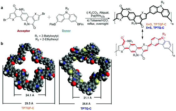
The semi-ladder polymers were synthesized via Suzuki coupling polymerization of electron-accepting monomer 5,11-bis(2-butyloctyl)-dihydrothieno[2′,3′:4,5]pyrido[2,3-g]thieno[3,2-c]quinoline-4,10-dione (TPTQ) or TPTQF dibromide with electron-donating chromophore carbazole (C) monomer containing bis(pinacolato)di-boron (BPin) moieties.25–29 The resulting polymers are cross-conjugated and exhibit excellent fluorescent properties (Fig. 1a). General synthetic procedures of the polymers are summarized in the ESI.† These polymers exhibited sizable molecular weights and generally narrow polydispersity indices (PDI) as summarized in Table S1.† TPTQ-C and TPTQF-C were soluble in common organic solvents such as p-xylene or chlorobenzene. The HOMO and LUMO energy levels of the polymers were calculated from the oxidation onset of cyclic voltammetry (CV) measurements and optical bandgap of thin films (Table S1†). The replacement of thiophene on TPTQ with furan (TPTQF) leads to slightly higher HOMO and LUMO energy levels and larger bandgaps. TPTQF-C and TPTQ-C exhibit EHOMO/ELUMO of −5.42/−3.04 eV, and −5.44/−3.19 eV, respectively. These energy levels are consistent with the energy levels calculated from the density functional theory (DFT) (B3LYP method, 6-31g** basis set) as shown in Fig. S1.† Notably, TPTQ-C exhibited a lower PLQY (30%) than TPTQF-C (50%) which may be attributed to the heavy atom effect (sulfur versus oxygen)30–32 and will play an important role on device performance. For comparison, linear semi-ladder polymers, TPTQF-CC and TPTQ-CC were also synthesized as shown in Scheme S1† and their chemical properties were summarized in Table S1 and Fig. S2.† The optimized geometry obtained from DFT calculations indicated that the cross-conjugated connection makes both TPTQF-C and TPTQ-C coiled with sizes of cross-section around 24.1 Å/29.5 Å and 21.1 Å/26.6 Å respectively (Fig. 1b).Optical properties and aggregations
The optical transitions in these cross conjugated polymers, monomers, and model compounds (carbazole-TPTQ(TPTQF)-carbazole) were investigated in detail by employing UV-vis spectrometer and the results are shown in Fig. 2a and S3.† The absorption spectra of the TPTQ monomer and model compound exhibited a strong 0–0 transition and weaker 0–1 transition. However, polymers TPTQ-C and TPTQF-C show a significant difference in spectral shape, where the 0–0 transition intensity is reduced and 0–1 transition becomes the strongest, indicating the formation of H-aggregates.22,23,33 Normalized absorption spectra showed almost no change in the spectral shape with decreasing concentration (Fig. 2), indicating that H aggregation exists even at the level of a single polymer chain. This is an evidence for polymer folding as shown in our previous work.34,35 In comparison, 0–0 transition intensity was reduced gradually and the whole absorption spectrum was blue shifted with increasing concentrations, as shown in linear polymer, TPTQ-CC (Fig. S4†), which exhibited unfolded H-aggregation. Fluorescence spectra under varied temperatures provided further evidence for polymer aggregation formation. It is known that the ratio of intensities of the I0–0 peak to the I0–1 peak will increase as the temperature increases for H-aggregation, and decrease for J-aggregation.23 As shown in Fig. S5 and Table S2,† TPTQF-C exhibited an increased I0–0/I0–1 ratio from 2.03 to 2.18 when the solution temperature increased from −9 to 20 °C which is consistent with H-aggregation (due to limitations in our instrument, we could only perform the measurements within this narrow temperature range). Similar trends were observed for polymer TPTQ-C. It was proposed that the formation of H-aggregates in normal semiconducting polymers is due to strong inter-chain interactions.23,33 The H-aggregation in these polymers, however, must be due to intrachain folding as concluded from the spectral analysis above. Due to intrachain H-aggregation, these foldamers exhibit modest PLQY in dilute chloroform solution (0.001 mg mL−1).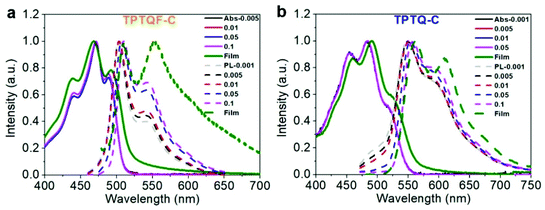 | ||
| Fig. 2 Concentration-dependent (mg mL−1) UV-vis absorption (Abs, solid line) and photoluminescence (PL, dotted line) spectra of (a) TPTQF-C and (b) TPTQ-C. | ||
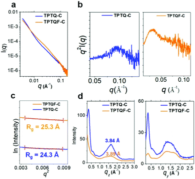
The direct evidence for folded structures came from small angle X-ray scattering (SAXS) measurements using advanced synchrotron light source.36,37 The SAXS profiles of TPTQF-C and TPTQ-C were obtained in THF solutions with a concentration of 5 mg mL−1, which were used to analyze the structure of the foldamer. As shown in Fig. 3, the two polymers showed strong scattering intensity I(q) at small scattering vector (q < 0.3 Å−1). After plotting the characteristic Kratky plots: q2 × I(q) vs. q, folded peaks were observed. Unlike the unfolded samples which have a plateau, the folded structures of TPTQF-C and TPTQ-C could be unambiguously identified in Fig. 3b.38 To calculate the particle size for the foldamers, the plots of ln[I(q)] vs. q2, were fitted with Guinier relationship: ln[I(q)] = ln[I0] − 1/3q2Rg2, where I0 is proportional to Mw and Rg is the size of the particle (Fig. 3c).36,38 The calculated particle size of TPTQF-C (25.3 Å) was relatively larger than that of TPTQ-C (24.3 Å) which is consistent with the simulated coiled structures (Fig. 1b).
The film photoluminescence spectra for the polymers showed a slight redshift in comparison with corresponding solution spectra. To understand these observations, we measured concentration-dependent photoluminescence spectra (Fig. 2). The range of concentrations used in our study was from 0.001 mg mL−1 to 0.1 mg mL−1. The polymers showed a gradual redshift of fluorescence upon concentration increase. The shoulder peaks (I0–1) were present even in the most dilute solution for all the polymers and their intensity increased with the increasing concentration. These results seem to be in contradiction with H-aggregates which are known to exhibit a blueshift. However, as demonstrated by Spano et al., polymers containing quadrupole interactions could exhibit a redshift in H-aggregates.24,39 As shown in Fig. 1a, the D–A−–D+ resonant structures indeed demonstrate a compound exhibiting quadrupole interactions. Thus, these polymers are special cases with quadrupole interactions that exhibit a redshift in H-aggregates. It is different from typical blue-shifted H-aggregate for small molecules, in which aggregates are mainly influenced by intermolecular interaction, while in polymers, the aggregation states are contributed from both interchain and intrachain interaction.23
To gain deeper insight into photophysical properties, time-resolved fluorescence decay measurements were performed with polymer solutions (Table S3†). Fluorescence decay curves were fitted with exponential decay equation and fluorescence lifetimes were calculated. It was found that polymer TPTQ-C exhibits the fluorescence lifetime (τ) of 2.14 ns with a single exponential decay curve. TPTQ-F showed double exponential decay behavior with τ1 (25%) = 0.77 ns, and τ2 (75%) = 2.44 ns, which may indicate the presence of different relaxation pathways in comparison with TPTQ-C. This value seemed to be consistent with folded H-aggregates in which exciton delocalization elongates the fluorescence lifetimes (Table S3†).
Microstructures and charge transporting properties
As shown in the two-dimensional (2D) grazing-incidence wide-angle X-ray scattering (GIWAXS) images (Fig. S6†) and profiles (Fig. 3d) of the polymer thin films, it was found that the polymers were almost amorphous, with a slight preference face-on orientation. TPTQ-C and TPTQF-C exhibited similar intermolecular π–π stacking distances of 3.84 and 3.89 Å respectively. Moreover, TPTQF-C and TPTQ-C showed p-type transport behavior and hole mobilities (μh) of 5.2 × 10⁻⁶ and 6.9 × 10⁻⁵ cm2 V−1 s−1 respectively (Tables S4 and S5†) in bottom gate top contact FET devices with gold as source and drain electrodes (Fig S9 and S10†). The modest charge mobilities and amorphous characters in the thin films, may be due to the tight intrachain folding. Expectedly, no electroluminescence was observed in single-layer FET devices, because of the large injection energy barrier (using the same drain-source electrodes) and low charge mobility in pristine films.Fabrication of multi-layered OLET and device performance
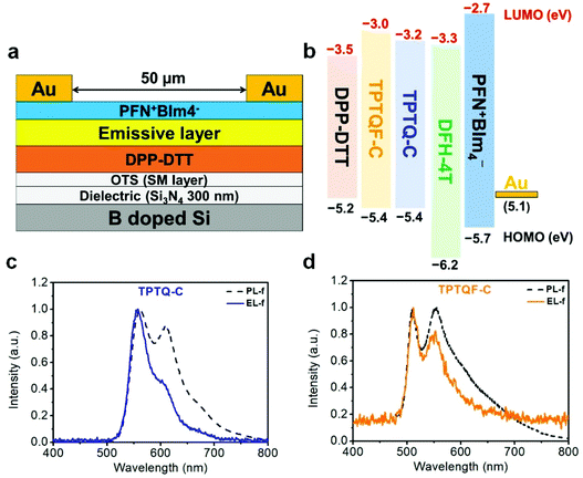
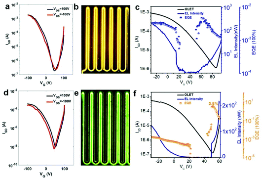
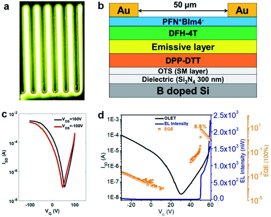
To address the issue about unbalanced charge injection, multi-layers including an electron injection layer, a charge transporting layer, an emissive layer, and a self-assembled monolayer (SAM) were integrated as a device configuration of (Si3N4/OTS/DPP-DTT/emissive layer/PFN+BIm4−/Au). SAM (n-octadecyltrichlorosilane, OTS) was vapor-deposited on SiNx as a modification layer at 120 °C in a vacuum oven to reduce charge trapping and to improve molecular stacking. From the energy level diagram (Fig. 4), the LUMO energy levels of these polymers were aligned too high relative to Au (workfunction, WAu = 5.1 eV) with the electron injection barrier as high as 2.0 eV. Therefore, a thin conjugated polyelectrolyte (CPE) PFN+BIm4− with a thickness of around 10 nm was inserted between gold (Au) and the emissive layer as an electron injection layer. The ionic effect of PFN+BIm4− effectively lowered the electron injection energy barrier.18 Since the thin film PFN+BIm4− was spin-coated from a methanol solution, we were able to avoid the dissolution of the emissive layer. The low charge mobility of pristine polymer films would impede the recombination of electron/hole pairs which dramatically decreases the electroluminescent efficiency. To address this issue, a charge transporting layer was inserted between the gate electrode and the emissive layer. After carefully testing different high mobility FET polymers, we found DPP-DTT suitable for our material (Fig. 4). DPP-DTT does not dissolve in p-xylene and exhibits high hole and electron mobility.40 Moreover, the HOMO (−5.2 eV) and LUMO (−3.5 eV) of DPP-DTT matches well with that of the emissive layer which should facilitate hole or electron transport from DPP-DTT back to the emissive polymers (Fig. 4b). The polymer emissive layer was then spin-coated from p-xylene to avoid the dissolution of DPP-DTT and then annealed at 120 °C. To simplify device fabrication, we employed symmetric drain/source electrodes.Transfer and output curves were measured at positive and negative source-drain voltages (VDS) to test for n-channel and p-channel in our device respectively. Fig. 5 shows that our OLET devices exhibit ambipolar behavior with V-shaped transfer curves. It is evident that the charge transport occurs predominantly at the DPP-DTT/dielectric interface. The calculated mobilities of TPTQF-C (μh = 2.5 × 10⁻² cm2 V−1 s−1; μe = 3.2 × 10⁻² cm2 V−1 s−1), and TPTQ-C (μh = 3.5 × 10⁻¹ cm2 V−1 s−1; μe = 5.1 × 10⁻¹ cm2 V−1 s−1), from transfer curves and Ion/off for tri-layered devices are several orders of magnitude larger than for single-layered devices (Table S4†). Our OLET devices for TPTQF-C and TPTQ-C exhibited strong yellow-green and yellow emission respectively, although the emission zone was fixed near the electrodes (Fig. 5). A detailed investigation into light emission revealed that the electroluminescence spectra of the polymers were very close to the 0–0 transition band in the film photoluminescence spectrum (Fig. 4c and d), indicating the identical nature of emissive centers for both PL and EL processes.
The transfer curves for the OLET device and the photocurrent for the reverse-biased photodiode were simultaneously measured by placing calibrated photodiode right in front of the device and observing the response. Based on the photocurrent obtained from photodiodes and source-drain current in OLET devices, we can measure the EL intensity and EQE of our OLET devices.41,42 As shown in Fig. 5c and f, the EL intensity decreased with decreasing gate voltages from negative to positive, and then increased with increasing gate voltages starting from around VG = 40 V. The EL intensity achieved for TPTQ-C (200 nW) and TPTQF-C (216 nW) were comparable to the best tri-layered OLET devices reported by Capelli et al.19 TPTQF-C showed the highest EQE of 3.5% at low applied voltages (VDS = 60 V, VG = 51 V) which was more than three orders of magnitude higher than that of the corresponding tri-layered OLED (Fig. S7†). In comparison, the intrinsically low PLQY in TPTQ-C, and larger source-drain current due to higher charge mobilities in tri-layered OLET devices (Table S4†), limited the electroluminescence efficiency, and led to an EQE of only 0.0050%. The same tri-layered OLETs of linear polymers, TPTQF-CC and TPTQ-CC, were fabricated and measured as shown in the ESI (Fig. S8 and Table S5†) for comparison. EL intensity (∼10−1 nW) and EQE obtained in OLET devices of TPTQF-CC (0.0032%) and TPTQ-CC (0.00022%) were much lower than the corresponding cross-conjugated coiled foldamers, TPTQF-C and TPTQ-C.
Since the highly fluorescent foldamer, TPTQF-C exhibited good performance in tri-layered OLET devices, further optimization of the device structure was essential. As shown in Fig. 5e, the charge carriers in the DPP-DTT layer recombined with the injection charge carriers from PFN+BIm4− near the electrodes and displayed a narrow emission zone, which behaved more like an OLED and limited the EQE. It was because the thin PFN+BIm4− layer was unable to transport charge carriers that led to the exciton quenching on gold.18 Thus, another charge transporting layer DFH-4T was inserted between the emissive layer and the charge injection layer as shown in Fig. 6 and 4b.43,44 The energy levels of this layer matched well with those of TPTQF-C. The LUMO (−3.3 eV) of DFH-4T aligns closely with the LUMO of TPTQF-C. The HOMO (−6.3 eV), however, was much lower than that of TPTQF-C. Moreover, DFH-4T showed high charge mobility of 0.5 cm2 V−1 s−1 which is comparable with that of DPP-DTT. As shown in Fig. 6a and S11,† the much stronger yellow-green emission zone in these new devices extended significantly and nearly covered the whole channel. This is in sharp contrast to the device shown in Fig. 5e. This demonstrated that the injection charge carriers in the DFH-4T layer can transport efficiently and recombine with charge carriers from DPP-DTT bottom layer in the middle of the emissive layer. Here, we observed impressive EL intensity (2332 nW) and EQE (6.9%) as shown in Fig. 6d. Notably, an interesting observation is that the emission zone is not a narrow line as observed in those single-layer devices.41 This may have complicated reasons. One explanation is likely due to multilayers so that the gating field sensed by the emission layer was broadened. A more detailed device investigation is in progress to elucidate this point.
Conclusions
Our results reveal that the semi-ladder copolymers TPTQ-C and TPTQF-C exhibiting a foldamer structure show balanced electrical and light-emitting properties. It is known that foldamers are well studied in biological macromolecules or synthetic polymers (oligomers) that adopt highly ordered helical-like self-assembling structures by non-covalent interactions.34–36,45 The investigation of foldamers provides insight into biological systems and is of great importance when developing new self-assembling materials. Artificial foldamers have shown promising applications in chiral recognition, circularly polarized luminescence, asymmetric catalysis, etc.45 Though chemists have proposed strategies for dye self-assembly,46,47 synthetic and design protocols for functional foldamers such as light-emitting materials are rare, if any. This is the first time anyone has demonstrated that coiled donor–acceptor semi-ladder polymers can form folded structures exhibiting superior device performance. The observed high EQE is remarkable considering the fact that the polymer exhibits only modest PLQY and low mobility. There are three factors that enhanced the EQE of the OLET device. The first is the unique structures of the foldamer that allows an optimal compromise in light emission and charge transport, leading to high EQEs. The second one is the inserted charge-transporting layers which balanced charge injection and transport so that excitons are formed away from the edge of electrodes, which is evident from the EL image. The third one is that emitted light can be extracted from top side in our bottom gate top contact configuration, and don't need to pass through the highly refractive transparent electrodes like OLED, which can achieve higher outcoupling efficiency. This design strategy may pave the way for the development of even more efficient polymers that can be used in the next generation of high-efficiency OLETs.Conflicts of interest
There are no conflicts to declare.Acknowledgements
We also thank Dr Joseph Strzalka and Dr Zhang Jiang for the assistance with GIWAXS measurements. This work was supported by NSF (Chem-1802274, LPY), partially supported by the University of Chicago Materials Research Science and Engineering Center, which is funded by the National Science Foundation under award number DMR-1420709. ChemMatCARS Sector 15 is supported by the National Science Foundation under grant number NSF/CHE-1834750. This research used resources of the Advanced Photon Source, a U.S. Department of Energy (DOE) Office of Science User Facility operated for the DOE Office of Science by Argonne National Laboratory under Contract No. DE-AC02-06CH11357.Notes and references
- L. Lu, T. Zheng, Q. Wu, A. M. Schneider, D. Zhao and L. Yu, Chem. Rev., 2015, 115, 12666–12731 CrossRef CAS.
- O. Ostroverkhova, Chem. Rev., 2016, 116, 13279–13412 CrossRef CAS.
- D. Zhang, T. Huang and L. Duan, Adv. Mater., 2019, e1902391 Search PubMed.
- M. Y. Wong and E. Zysman-Colman, Adv. Mater., 2017, 29, 1605444 CrossRef.
- C. Zhang, P. Chen and W. Hu, Small, 2016, 12, 1252–1294 CrossRef CAS.
- C. F. Liu, X. Liu, W. Y. Lai and W. Huang, Adv. Mater., 2018, 30, e1802466 CrossRef.
- J. Zaumseil, Adv. Funct. Mater., 2019, 30, 1905269 CrossRef.
- D. Yuan, V. Sharapov, X. Liu and L. Yu, ACS Omega, 2020, 5, 68–74 CrossRef CAS.
- M. Muccini, W. Koopman and S. Toffanin, Laser Photonics Rev., 2012, 6, 258–275 CrossRef CAS.
- S. Z. Bisri, C. Piliego, J. Gao and M. A. Loi, Adv. Mater., 2014, 26, 1176–1199 CrossRef CAS.
- A. S. D. Sandanayaka, T. Matsushima, F. Bencheikh, S. Terakawa, W. J. Potscavage, C. Qin, T. Fujihara, K. Goushi, J.-C. Ribierre and C. Adachi, Appl. Phys. Express, 2019, 12, 061010 CrossRef CAS.
- D. Liu, J. De, H. Gao, S. Ma, Q. Ou, S. Li, Z. Qin, H. Dong, Q. Liao, B. Xu, Q. Peng, Z. Shuai, W. Tian, H. Fu, X. Zhang, Y. Zhen and W. Hu, J. Am. Chem. Soc., 2020, 142, 6332–6339 CrossRef CAS.
- A. Dadvand, A. G. Moiseev, K. Sawabe, W. H. Sun, B. Djukic, I. Chung, T. Takenobu, F. Rosei and D. F. Perepichka, Angew. Chem., Int. Ed., 2012, 51, 3837–3841 CrossRef CAS.
- J. Liu, H. Zhang, H. Dong, L. Meng, L. Jiang, L. Jiang, Y. Wang, J. Yu, Y. Sun, W. Hu and A. J. Heeger, Nat. Commun., 2015, 6, 10032 CrossRef CAS.
- J. Li, K. Zhou, J. Liu, Y. Zhen, L. Liu, J. Zhang, H. Dong, X. Zhang, L. Jiang and W. Hu, J. Am. Chem. Soc., 2017, 139, 17261–17264 CrossRef CAS.
- Z. Qin, H. Gao, J. Liu, K. Zhou, J. Li, Y. Dang, L. Huang, H. Deng, X. Zhang, H. Dong and W. Hu, Adv. Mater., 2019, 31, e1903175 CrossRef.
- X. Zhang, H. Dong and W. Hu, Adv. Mater., 2018, 30, e1801048 CrossRef.
- J. H. Seo, E. B. Namdas, A. Gutacker, A. J. Heeger and G. C. Bazan, Adv. Funct. Mater., 2011, 21, 3667–3672 CrossRef CAS.
- R. Capelli, S. Toffanin, G. Generali, H. Usta, A. Facchetti and M. Muccini, Nat. Mater., 2010, 9, 496–503 CrossRef CAS.
- M. Prosa, E. Benvenuti, M. Pasini, U. Giovanella, M. Bolognesi, L. Meazza, F. Galeotti, M. Muccini and S. Toffanin, ACS Appl. Mater. Interfaces, 2018, 10, 25580–25588 CrossRef CAS.
- H. Chen, X. Xing, J. Miao, C. Zhao, M. Zhu, J. Bai, Y. He and H. Meng, Adv. Opt. Mater., 2020, 8, 1901651 CrossRef CAS.
- Y. Deng, W. Yuan, Z. Jia and G. Liu, J. Phys. Chem. B, 2014, 118, 14536–14545 CrossRef CAS.
- F. C. Spano and C. Silva, Annu. Rev. Phys. Chem., 2014, 65, 477–500 CrossRef CAS.
- C. Zheng, C. Zhong, C. J. Collison and F. C. Spano, J. Phys. Chem. C, 2019, 123, 3203–3215 CrossRef CAS.
- I. H. Jung, D. Zhao, J. Jang, W. Chen, E. S. Landry, L. Lu, D. V. Talapin and L. Yu, Chem. Mater., 2015, 27, 5941–5948 CrossRef CAS.
- Z. Cai, M. A. Awais, N. Zhang and L. Yu, Chem, 2018, 4, 2538–2570 CAS.
- O. Usluer, S. Demic, D. A. M. Egbe, E. Birckner, C. Tozlu, A. Pivrikas, A. M. Ramil and N. S. Sariciftci, Adv. Funct. Mater., 2010, 20, 4152–4161 CrossRef CAS.
- A. Enriquez-Cabrera, P. G. Lacroix, I. Sasaki, S. Mallet-Ladeira, N. Farfán, R. M. Barba-Barba, G. Ramos-Ortiz and I. Malfant, Eur. J. Inorg. Chem., 2018, 531–543 CrossRef CAS.
- J. Xu, Q. Ji, L. Kong, H. Du, X. Ju and J. Zhao, Polymers, 2018, 10, 450 CrossRef.
- I. B. Berlman, J. Phys. Chem., 1973, 77, 562–567 CrossRef CAS.
- H. Dreeskamp, E. Koch and M. Zander, Chem. Phys. Lett., 1975, 31, 251–253 CrossRef CAS.
- S. Hamai, Bull. Chem. Soc. Jpn., 1984, 57, 2700–2702 CrossRef CAS.
- F. C. Spano, Acc. Chem. Res., 2010, 43, 429–439 CrossRef CAS.
- T. J. Fauvell, T. Zheng, N. E. Jackson, M. A. Ratner, L. Yu and L. X. Chen, Chem. Mater., 2016, 28, 2814–2822 CrossRef CAS.
- X. Hu, J. O. Lindner and F. Wurthner, J. Am. Chem. Soc., 2020, 142, 3321–3325 CrossRef CAS.
- R. F. Kelley, B. Rybtchinski, M. T. Stone, J. S. Moore and M. R. Wasielewski, J. Am. Chem. Soc., 2007, 129, 4114–4115 CrossRef CAS.
- T. Li, A. J. Senesi and B. Lee, Chem. Rev., 2016, 116, 11128–11180 CrossRef CAS.
- C. D. Putnam, M. Hammel, G. L. Hura and J. A. Tainer, Q. Rev. Biophys., 2007, 40, 191–285 CrossRef CAS.
- F. Terenziani, A. Painelli, C. Katan, M. Charlot and M. Blanchard-Desce, J. Am. Chem. Soc., 2006, 128, 15742–15755 CrossRef CAS.
- J. Li, Y. Zhao, H. S. Tan, Y. Guo, C. A. Di, G. Yu, Y. Liu, M. Lin, S. H. Lim, Y. Zhou, H. Su and B. S. Ong, Sci. Rep., 2012, 2, 754 CrossRef.
- J. Zaumseil, C. L. Donley, J. S. Kim, R. H. Friend and H. Sirringhaus, Adv. Mater., 2006, 18, 2708–2712 CrossRef CAS.
- M. C. Gwinner, D. Kabra, M. Roberts, T. J. Brenner, B. H. Wallikewitz, C. R. McNeill, R. H. Friend and H. Sirringhaus, Adv. Mater., 2012, 24, 2728–2734 CrossRef CAS.
- H. Usta, A. Facchetti and T. J. Marks, Acc. Chem. Res., 2011, 44, 501–510 CrossRef CAS.
- A. Facchetti, M. Mushrush, M.-H. Yoon, G. R. Hutchison, M. A. Ratner and T. J. Marks, J. Am. Chem. Soc., 2004, 126, 13859–13874 CrossRef CAS.
- E. Yashima, N. Ousaka, D. Taura, K. Shimomura, T. Ikai and K. Maeda, Chem. Rev., 2016, 116, 13752–13990 CrossRef CAS.
- F. Würthner, C. R. Saha-Möller, B. Fimmel, S. Ogi, P. Leowanawat and D. Schmidt, Chem. Rev., 2016, 116, 962–1052 CrossRef.
- M. R. Wasielewski, Acc. Chem. Res., 2009, 42, 1910–1921 CrossRef CAS.
Footnotes |
| † Electronic supplementary information (ESI) available: Experimental details, and additional figures. See DOI: 10.1039/d0sc04068a |
| ‡ These authors contributed equally. |
| This journal is © The Royal Society of Chemistry 2020 |

