 Open Access Article
Creative Commons Attribution 3.0 Unported Licence
Gold nanocages for effective photothermal conversion and related applications
Jichuan
Qiu†
 a,
Minghao
Xie†
b,
Tong
Wu†
 a,
Dong
Qin
 c and
Younan
Xia
 *ab
*ab
aThe Wallace H. Coulter Department of Biomedical Engineering, Georgia Institute of Technology and Emory University, Atlanta, GA 30332, USA. E-mail: younan.xia@bme.gatech.edu
bSchool of Chemistry and Biochemistry, Georgia Institute of Technology, Atlanta, GA 30332, USA
cSchool of Materials Science and Engineering, Georgia Institute of Technology, Atlanta, GA 30332, USA
First published on 19th October 2020
Abstract
Gold nanocages (AuNCs) are a class of hollow nanocrystals with ultrathin and porous walls made of Au or Au-based alloys. When interacting with light, AuNCs exhibit a large absorption cross section and a high efficiency for light-to-heat conversion, making them effective photothermal transducers. Significantly, their absorption peak can be easily and precisely tuned through the visible and near-infrared regions to optimize their interaction with light of different wavelengths. As an inorganic nanomaterial, AuNCs have much better photo-stability compared to conventional organic dyes. This perspective summarizes recent progress in controlling the synthesis of AuNCs, together with their use in applications involving photothermal conversion. In the synthesis part, we pay particular attention to the strategies developed for tuning their size, shape, and composition, as well as the thickness and porosity of the walls. We then discuss the photothermal properties of AuNCs in terms of both theoretical calculations and experimental measurements, followed by a number of examples to highlight their applications in the context of light detection, water evaporation, phase transition, controlled release, and photothermal therapy. At the end, we offer some perspectives on the challenges and opportunities with respect to both the synthesis and application of AuNCs.
1. Introduction
Gold nanocages (AuNCs) have garnered considerable attention since they were invented in 2002 because of their unique optical properties.1 They have been demonstrated for use as light sensors, imaging contrast agents, photothermal transducers, and drug carriers in a wide variety of applications related to optics, plasmonics, and nanomedicine.2–5 In essence, AuNCs refer to a class of hollow nanocrystals with their porous walls made of Au or Au-based alloys. The empty interior inside the nanocage not only provides a void space for encapsulating a large amount of payload(s) but also makes it possible to minimize the use of Au, which is a particularly important aspect for the development of cost-effective gold nanoparticles considering the scarcity and high price of this element.6 At the same time, the pores in the walls offer a quick and easy avenue for the loading and release of various types of payloads. The pores can be further designed with the “open or close” gating capability by integration with stimuli-responsive materials to enable on-demand release and thus applications in drug delivery.7As another signature of AuNCs, their localized surface plasmon resonance (LSPR) peaks can be easily and precisely tuned in the visible and near-infrared (NIR) regions by varying their size, shape, and composition, as well as the thickness and porosity of the walls.8 In addition, AuNCs have a large absorption cross section and a high efficiency for light-to-heat conversion, making them remarkable photothermal transducers for achieving quick elevation of the local temperature.9 When their absorption peaks are tuned into the transparent window (700–900 nm) of soft tissues, AuNCs can serve as contrast agents for imaging modalities such as photoacoustic tomography (PAT) and as photothermal agents for the treatment of malignance occurring deeply below the skin through photothermal therapy, temperature-controlled drug release, and a combination of them. When used as photothermal transducers, AuNCs display much better photo-stability compared to conventional organic dyes, which are well-known for their susceptibility to photobleaching.4
In this perspective, we summarize some of the recent developments in the fabrication and photothermal applications of AuNCs. We begin with an introduction to two general methods for the synthesis of AuNCs: (i) a template-engaged galvanic replacement reaction and (ii) seed-mediated growth, followed by selective etching. We pay particular attention to the capability of each method in controlling the size, shape, and composition of the nanocages, as well as the thickness and porosity of the walls. We then discuss the photothermal properties of AuNCs from the viewpoints of both theoretical calculations and experimental measurements. Afterwards, we showcase a set of photothermal applications of AuNCs in the context of light detection, water evaporation, phase transition, controlled release, and photothermal therapy. At the end, we offer some perspectives on the challenges and outlooks with respect to both synthesis and application.
2. Synthesis of AuNCs
2.1. Template-engaged galvanic replacement
The most commonly used method for the fabrication of AuNCs is based upon the galvanic replacement reaction between Ag nanocubes and HAuCl4 in an aqueous medium,8 which can be written as the following equation:| 3Ag(s) + AuCl4−(aq) → Au(s) + 3Ag+(aq) + 4Cl−(aq) | (1) |
This reaction occurs spontaneously because AuCl4−/Au (1.00 V) has a more positive standard reduction potential relative to that of Ag+/Ag (0.80 V). As such, AuNCs can be conveniently obtained by simply titrating an aqueous HAuCl4 solution into an aqueous suspension containing Ag nanocubes and poly(vinylpyrrolidone) (PVP). In this process, Ag atoms are gradually oxidized and dissolved while the generated Au atoms are simultaneously deposited on the surface of the Ag nanocubes, finally generating AuNCs.3,10
The morphological and compositional changes involved in the transformation from a Ag nanocube to a AuNC are illustrated in Fig. 1A. For the Ag nanocube with sharp corners, the oxidation and dissolution of Ag were initiated at a high-energy site (e.g., surface step and terrace, as well as a region low in PVP coverage) on its surface, resulting in the generation of a pinhole on the side face. The initially formed pinhole then acted as an anode for the continuous oxidation and dissolution of Ag, accompanied by the epitaxial growth of Au on the surface of the Ag nanocube. As more Au atoms were deposited, the pinhole gradually closed due to atomic diffusion and/or direct deposition of Au. At the reaction temperature used, the inter-diffusion between Ag and Au would promote the formation of an alloy at the interface of Ag and Au, converting the Ag nanocube into a Au–Ag nanobox with uniform wall thickness. Once all the pure Ag in the interior had been removed, addition of more HAuCl4 would lead to the dealloying of Ag from the alloy walls, introducing vacancies in the walls as the removal of three Ag atoms only resulted in the deposition of one Au atom (see eqn (1)). During this process, the nanobox would be truncated first to minimize the total energy of the structure, followed by generation of pores in the side faces. The dealloying process could also be achieved using wet etchants such as Fe(NO3)3 or H2O2 to selectively remove Ag.11,12
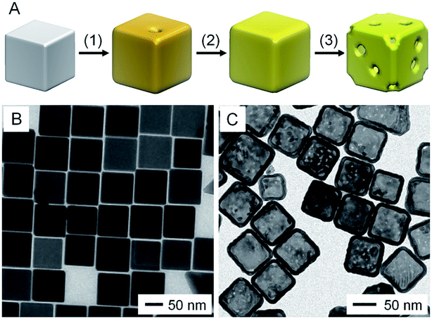 | ||
| Fig. 1 Template-engaged galvanic replacement reaction. (A) Schematic illustration showing the morphological evolution involved in the galvanic replacement reaction between aqueous HAuCl4 and a Ag nanocube with sharp corners: (1) initial dissolution of Ag and deposition of Au on the surface of the Ag nanocube; (2) further deposition of Au, initiating the alloying between Au and Ag; (3) dealloying of Ag from the alloyed nanostructures, increasing the porosity of the walls. TEM images of (B) Ag nanocubes with sharp corners (with an average edge length of 86 nm) and (C) the resultant AuNCs with pores of 2–4 nm in the surface. (B) Reproduced from ref. 13 with permission from American Chemical Society. Copyright 2016. (C) Reproduced from ref. 14 with permission from Wiley-VCH. Copyright 2019. | ||
Fig. 1B shows a transmission electron microscopy (TEM) image of Ag nanocubes with sharp corners, which had an average edge length of 86 nm.13Fig. 1C shows the resultant AuNCs with multiple small pores of 2–4 nm in diameter in the walls.14 Notably, when the Ag nanocubes were truncated at corners and then used as the starting material, the dissolution of Ag throughout the galvanic replacement reaction would be confined to the corners because the (111) facets at the corners were not covered by PVP.15 The deposition of Au mainly occurred on the side faces, where the {100} facets were covered with PVP, leading to the generation of AuNCs with well-defined pores at all corners. Even though this method is quite simple and suitable for large-scale production of AuNCs, the reduction of AuCl4− and oxidation of Ag occur simultaneously in the galvanic replacement process, making it difficult to control the structure, especially the wall thickness, of the final products.
2.2. Seed-mediated deposition, followed by etching of Ag
To address the problem in the galvanic replacement process, a new method involving seed-mediated deposition of Au, followed by etching of Ag from the core, was developed for better controlling the structure (Fig. 2A).11 In this approach, a strong reducing agent such as ascorbic acid was introduced to reduce HAuCl4 while suppressing the galvanic replacement reaction between HAuCl4 and Ag.11,16–18 In the meantime, NaOH was added to adjust the pH of the reaction system to 11.2 for selectively generating Ag2O patches at the corner sites of the Ag nanocube.11 After deposition of a conformal shell of Au on the surface of the Ag nanocube, the Ag2O patches were removed with a weak acid such as citric acid. During this process, the Au overlayers deposited on top of Ag2O patches would be peeled off, exposing the Ag at the corner sites. As a result, the Ag core could be completely etched away with an aqueous H2O2 solution, generating a AuNC with a uniform wall thickness and well-defined pores at the corners.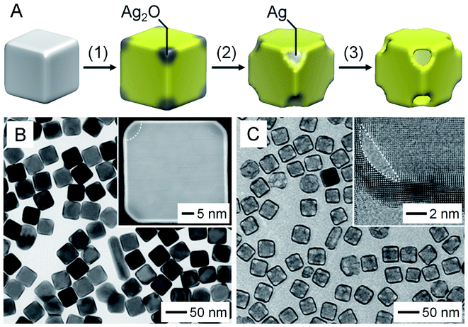 | ||
| Fig. 2 Seed-mediated growth, followed by etching. (A) Schematic illustration of the three major steps involved in the fabrication of a AuNC through seed-mediated deposition of Au on a Ag nanocube: (1) conformal deposition of Au with the formation of Ag2O at the corners; (2) dissolution of Ag2O; (3) removal of the Ag core. (B) TEM image of Ag@Au6L nanocubes. The inset shows the HAADF-STEM image taken from an individual Ag@Au6L nanocube with Ag2O patches at corners. (C) TEM image of the AuNCs obtained by removing the Ag cores. The inset shows a high-resolution TEM image taken from the corner region of a AuNC. Reproduced from ref. 11 with permission from American Chemical Society. Copyright 2016. | ||
Fig. 2B shows a TEM image of Ag nanocubes after the conformal deposition of the Au shell. The inset shows a high-angle annular dark-field scanning transmission electron microscopy (HAADF-STEM) image of a representative particle, confirming the uniform thickness of the Au shell. The Ag2O patches at the corners were indicated by a relatively darker contrast. Fig. 2C shows a TEM image of the as-obtained AuNCs after sequential removal of Ag2O and Ag, which had uniform pores at the corners, together with a uniform wall of less than 2 nm in thickness. More significantly, the thickness of the Au shells could be controlled down to one atomic layer of Au by varying the amount of HAuCl4 involved.18 Compared to the template-engaged galvanic replacement reaction, this method requires additional steps with precise controls of experimental parameters in order to separate the deposition of Au from the removal of Ag.
2.3. Variations and controls in terms of size, shape, and wall thickness
The aforementioned methods for the fabrication of AuNCs both involve the use of Ag nanocrystals as templates. To this end, one can routinely tune the size and shape of the nanocages by simply switching to Ag nanocrystals with different sizes and shapes. For example, AuNCs with an octahedral shape (Fig. 3A) could be obtained by templating with Ag octahedra.19 In addition to the template, a capping agent can also be introduced to help control the final morphology of the nanocages.20 For instance, in the synthesis of AuNCs templating with Ag cuboctahedra, when PVP was employed as a capping agent, the openings were formed on the {111} facets because the oxidation of Ag preferred to occur on the {111} facets lower in PVP coverage (Fig. 3B).21 In contrast, when cetyltrimethylammonium chloride (CTAC) instead of PVP was used, the oxidation of Ag would occur on the {100} facets, leading to the generation of openings on the {100} facets (Fig. 3C). One can also tune the surface morphology of AuNCs by controlling the reaction kinetics. For example, concave AuNCs could be obtained by adjusting the initial pH of the reaction to the range of 3.2–4.8 and thus decreasing the reduction rate of HAuCl4.22 It is worth mentioning that the templates used for the production of AuNCs can also be extended from Ag to other metals such as Pd, Co, and Cu. Fig. 3D shows a TEM image of AuNCs with an icosahedral shape, which were fabricated by templating with Pd icosahedral nanocrystals.23 Such an extension made it possible to fabricate AuNCs with sizes below 10 nm due to the availability of Pd nanocrystals as small as 5 nm in size.24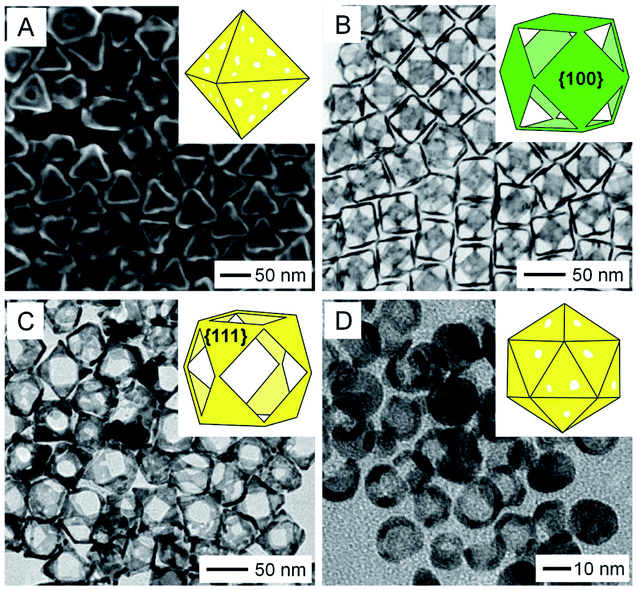 | ||
| Fig. 3 Variations in size, shape, and porosity. (A) SEM image of octahedral AuNCs with an edge length of 65 nm. TEM images of Au cuboctahedral nanocages with the pores located on the (B) {111} and (C) {100} facets, respectively. (D) TEM image of AuNCs prepared using Pd icosahedral nanocrystals as templates. The insets in (A–D) show the schematic models of the corresponding nanocages. (A) Reproduced from ref. 19 with permission from American Chemical Society. Copyright 2013. (B and C) Reproduced from ref. 21 with permission from the Royal Society of Chemistry. Copyright 2020. (D) Reproduced from ref. 23 with permission from Elsevier. Copyright 2017. | ||
In addition to the above methods, the structure and morphology of AuNCs can be further tuned by post-deposition of other materials on their surface. In one demonstration, Pd was coated on the surface of AuNCs to obtain Au–Pd nanocages.25 More significantly, by controlling the reduction kinetics, the deposition of Pd could be directed to occur on the outer surface only or on both the outer and inner surfaces (Fig. 4A). Fig. 4B shows a TEM image of the Au–Pd nanocages with Pd deposited on the outer surface only by leveraging the fast reduction of PdCl42−. When the reduction rate was slowed down by switching to PdBr42−, Au–Pd nanocages with Pd on both the outer and inner surfaces were obtained (Fig. 4C). Besides metals, polymers such as polypyrrole could also be deposited on both the inner and outer surfaces of AuNCs by ensuring diffusion of the pyrrole monomer through the porous walls, followed by polymerization.14 Taking together, control over the size, shape, wall thickness, and composition can significantly expand the diversity of AuNCs, making their optical and photothermal properties (such as LSPR, absorption cross section, etc.) readily tunable and thus broadening and strengthening their applications in various areas.3,9 In addition, when applied to in vivo applications, the size and shape of AuNCs may also affect their biodistribution and thus therapeutic efficacy.26,27
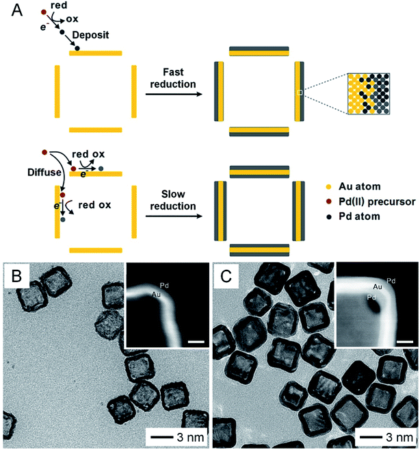 | ||
| Fig. 4 Expanding the diversity through the deposition of a second material. (A) Schematic illustration showing the deposition of Pd on the surface of AuNCs. Pd is only deposited on the outer surface with fast reduction kinetics while it can be deposited on both the outer and inner surfaces with slow reduction kinetics. TEM images of AuNCs after Pd had been deposited (B) on the outer surface only and (C) on both the outer and inner surfaces. The insets show enlarged HAADF-STEM images taken from the corners of the corresponding samples (scale bars: 5 nm). Reproduced from ref. 25 with permission from American Chemical Society. Copyright 2017. | ||
3. Photothermal properties
3.1. Scattering, absorption, and photothermal conversion
One of the most fascinating properties of Au nanostructures is LSPR, which refers to the scattering and absorption of incident light at a resonant frequency due to the collective oscillation of conduction electrons at the surface of the nanostructure.28–31 Such an interaction is responsible for the ruby red color displayed by the conventional Au colloid. As for AuNCs, their LSPR peak position can be readily tuned by controlling the extent of the galvanic replacement reaction and thus the composition, thickness, and porosity of the walls. Fig. 5A shows UV-vis-NIR spectra recorded from aqueous suspensions of AuNCs prepared by mixing different amounts of aqueous HAuCl4 with the same amount of Ag nanocubes, demonstrating the capability to tune the LSPR peak position from the visible region (about 400 nm for Ag nanocubes) to the NIR region (up to 1200 nm).8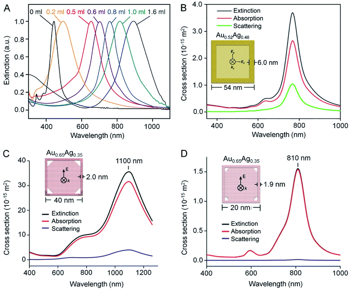 | ||
| Fig. 5 Optical properties of AuNCs. (A) Extinction spectra recorded from an aqueous suspension of Ag nanocubes after reaction with different amounts of HAuCl4 solution. (B–D) Extinction, absorption, and scattering spectra calculated using the DDA method for one AuNC dispersed in water (n = 1.33). In (B), the AuNC was modeled with an outer edge length of 54 nm, a wall thickness of 6 nm, and a composition of 52% Au and 48% Ag. In (C), the AuNC was modeled with an outer edge length of 40 nm, a wall thickness of 2 nm, a pore size of 10 nm at each corner, and a composition of 65% Au and 35% Ag. In (D), the AuNC was modeled with an outer edge length of 20 nm, a wall thickness of 1.9 nm, a pore size of 3 nm at each corner, and a composition of 65% Au and 35% Ag. The propagation direction (k-vector) and electric field (E-field) were indicated in the models in the insets. (A) Reproduced from ref. 8 with permission from Springer Nature. Copyright 2007. (B) Reproduced from ref. 33 with permission from the Royal Society of Chemistry. Copyright 2018. (C and D) Reproduced from ref. 11 with permission from American Chemical Society. Copyright 2016. | ||
When interacting with AuNCs, the extinction of the incident light can be expressed as a sum of scattering and absorption. The absorbed light can be rapidly converted to heat through a series of photo-physical processes.28,29 The generated heat (Q) has a positive correlation with the absorption cross section (C) and laser fluence (I) and it can be calculated using the following equation:32
| Q = C × I | (2) |
Remarkably, a AuNC has an absorption cross section almost five orders of magnitude greater than that of a conventional NIR dye such as indocyanine green, resulting in extraordinary light-to-heat conversion efficiency.9 More significantly, AuNCs are inorganic single crystals with good mechanical and photothermal stability, making them more robust in various applications compared to organic dyes, which are susceptible to photobleaching.4 In the meantime, the LSPR peak of AuNCs can be easily tuned into the transparent window (700–900 nm) of soft tissues, enabling an array of biomedical applications ranging from photothermal therapy to temperature-controlled drug release.
3.2. Discrete dipole approximation calculations
According to eqn (2), the photothermal conversion efficiency of a AuNC is directly dependent on its absorption cross section, which can be calculated using discrete dipole approximation (DDA).9Fig. 5B shows the calculated scattering, absorption, and extinction spectra of a nanocage composed of 52% Au and 48% Ag with an outer edge length of 54 nm and a wall thickness of 6 nm.33 The calculated scattering, absorption, and extinction cross sections at resonance were 1.04 × 10⁻¹⁴, 2.65 × 10⁻¹⁴, and 3.69 × 10⁻¹⁴ m2, respectively. The relative contributions of scattering and absorption to the total extinction of a AuNC can be tuned by varying its size. For example, when the outer edge length of the AuNC was reduced below 45 nm, the absorption dominated the light extinction, while scattering gradually prevailed when the size was increased.34 As shown in Fig. 5C and D, the scattering cross section became much diminished and even disappeared when the outer edge length of AuNCs was reduced to 40 and 20 nm, respectively.11 In principle, one can rationally select AuNCs with the right parameters to fit specific applications. For instance, AuNCs with large absorption cross sections are ideal for applications involving photothermal conversion whereas those with large scattering cross sections can serve as contrast agents for optical imaging modalities such as dark-field optical microscopy and optical coherence tomography (OCT).2,293.3. Experimental measurements
While DDA calculations can be conducted to easily obtain theoretical values of scattering and absorption cross sections, experimental measurements of these parameters have been challenging because of the difficulty in separating absorption from scattering for the extinction spectra recorded using a UV-vis-NIR spectrometer. In addressing this challenge, our group developed a protocol based on photoacoustic (PA) imaging to measure the absorption cross section of AuNCs.35 The setup is illustrated in Fig. 6A. When an aqueous solution of AuNCs was irradiated by a pulsed laser, PA waves would be generated due to thermoelastic expansion and contraction when optical absorption was turned on and off. The PA signals could be detected using an ultrasound transducer. The collected signals were then amplified and analyzed. Fig. 6B shows typical depth-resolved, two-dimensional PA images of AuNCs with an edge length of 45 nm at concentrations of 0.13, 0.07, and 0.03 nM, respectively. Within a certain range, the intensity of PA signals increased linearly as the concentration of AuNCs was increased (Fig. 6C). The absorption coefficient of AuNCs could be derived from the PA signals by benchmarking against the aqueous solution of methylene blue which has a known absorption cross section. For AuNCs with edge lengths of 45 and 32 nm, respectively, their absorption cross sections were measured to be 6.0 × 10⁻¹⁵ and 3.0 × 10⁻¹⁵ m2, in agreement with the calculation results from DDA.35 It is worth mentioning that the absorption cross sections of these two types of nanocages were both greater than that of Au nanorods of 44 nm × 19.8 nm in length × width (Fig. 6C).35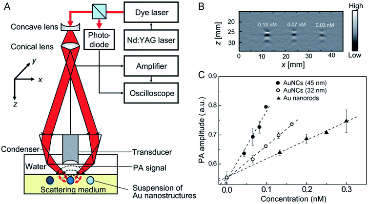 | ||
| Fig. 6 Evaluating the photothermal properties through PA imaging. (A) Schematic illustration of the setup for PA imaging. (B) A 2-D PA image of aqueous suspensions of AuNCs at three different concentrations: 0.13, 0.07, and 0.03 nM. (C) Plots of the correlation between the PA signal amplitude and the concentration of AuNCs and Au nanorods. Reproduced from ref. 35 with permission from American Chemical Society. Copyright 2009. | ||
The absorption cross section and photothermal conversion efficiency of AuNCs could also be measured by leveraging the temperature-caused volumetric expansion of a fluidic medium in a simple optofluidic device.36Fig. 7A shows a schematic, together with a photograph, of the optofluidic system. This system contains a diode laser as the light source, an aqueous suspension of AuNCs as the photothermal transducer, and a microfluidic device for measuring the volumetric expansion of the aqueous medium under photothermal heating. The volumetric changes can be derived from the height of the aqueous medium in the capillary, which has a linear relationship with the temperature of the medium (Fig. 7B). By benchmarking against an organic dye (e.g., indocyanine green) with a known molecular absorption coefficient, the absorption cross section and photothermal conversion efficiency of the AuNCs with an outer edge length of 45 nm and a wall thickness of 5 nm (at a concentration of 1.0 × 10¹⁰ particles per mL) were measured to be 12.4 × 10⁻¹⁵ m2 and 63.6%, respectively. Although such a device still needs to be improved in terms of heat insulation and accuracy, the simple design makes it easy to implement and use.
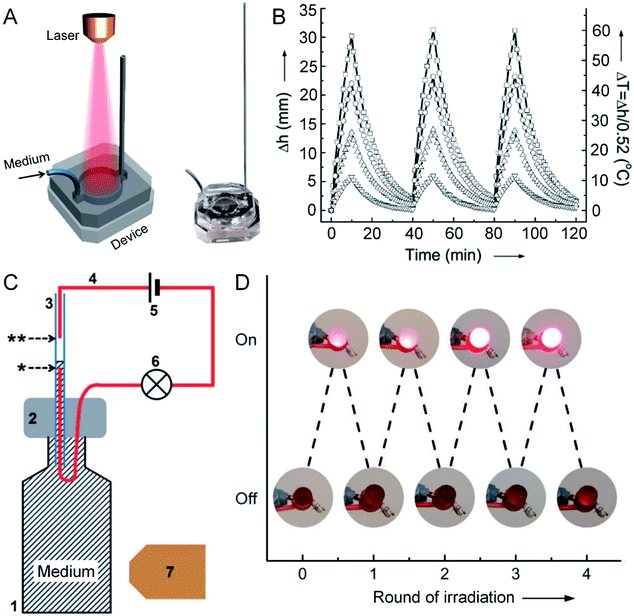 | ||
| Fig. 7 Measuring the photothermal conversion efficiency using an optofluidic device. (A) Schematic illustration of the optofluidic device, with the right panel showing a photograph of the device. (B) Plots showing the correlation between the rise in height (Δh) and the increase in temperature (ΔT) of the aqueous suspensions of AuNCs upon irradiation as a function of time. The AuNCs were tested at four different concentrations: 1.0 × 10⁹ (▽), 2.5 × 10⁹ (△), 5.0 × 10⁹ (○), and 1.0 × 10¹⁰ (□) particles per mL. In each cycle, the AuNCs were irradiated for 10 min, followed by cooling down for 30 min. (C) Schematic illustration of a photo-responsive electrical switch: (1) a glass vial filled with a suspension of AuNCs; (2) PDMS for sealing the vial; (3) capillary tube; (4) copper wire; (5) battery; (6) LED; (7) diode laser. Upon laser irradiation, the volume of the AuNC suspension expanded, bridging the gap between the two wires in the capillary (as marked by * and ** symbols), and thus turning on the LED. (D) Demonstration of the on/off switching of an LED over four cycles of laser irradiation. Reproduced from ref. 36 with permission from Wiley-VCH. Copyright 2013. | ||
Furthermore, this optofluidic device could be transformed into a photo-sensitive electrical switch by leveraging the fluid motion in the capillary.37 In this case, a small amount of NaCl was introduced into the aqueous suspension of AuNCs, i.e. the fluidic medium, to make it conductive. Fig. 7C shows a schematic of the photo-sensitive electrical switch. When the aqueous medium was irradiated with a laser, it heated up and expanded along the capillary, bridging the gap between two wires in the capillary (as marked by * and ** symbols in Fig. 7C) and completing an electrical circuit. The connection would turn on the light-emitting diode (LED). After turning off the laser irradiation, the aqueous solution would drop back, switching off the LED. The electrical switch could be operated through four cycles of on/off irradiations without losing its performance (Fig. 7D). Obviously, such a AuNC-based electrical switch can also serve as a sensor for the detection of light.
4. Applications
Due to their high efficiency in converting light to heat, AuNCs have been extensively explored as photothermal transducers for a wide variety of applications, including light detection, water evaporation, phase transition, controlled release, and photothermal therapy.4.1. Light detection
In Section 3.3, we have discussed an example of such an application in terms of constructing a photo-sensitive electrical switch. The same device can also be adapted for the detection of NIR light. The detection mechanism would be simply based on the volumetric expansion of an aqueous medium containing a certain concentration of AuNCs whose LSPR peak has been tuned to the wavelength of interest. In addition to this system, AuNCs can also be used for light detection through integration with a pyroelectric material such as poly(vinylidene fluoride) (PVDF), due to its capability to convert thermal energy to electricity. In one demonstration, AuNCs with their LSRP peak tuned to 800 nm were directly incorporated into PVDF nanofibers during electrospinning.33Fig. 8A shows a schematic of the AuNC/PVDF composite nanofiber mat-based device for NIR detection. When subjected to on/off irradiation cycles using an 808 nm laser at an irradiance of 0.2 W cm−2, the temperature of the AuNC/PVDF mat quickly increased by as much as 51.3 °C due to the strong absorption of the light by the AuNCs and then decreased to room temperature as the laser was turned off (Fig. 8B). The corresponding changes of the voltages between the two electrodes deposited on the mat were recorded in Fig. 8C. A voltage output of 7.2 V was achieved when the device was subjected to the on/off irradiation cycles at an irradiance of 0.2 W cm−2. In comparison, essentially no voltage output was detected when nanofibers made of pure PVDF were used. Notably, the presence of AuNCs and the strong electric field inherent to electrospinning both promoted the formation of the ferroelectric β phase in PVDF for achieving maximal pyroelectric conversion, enabling greatly enhanced capability toward NIR detection. Taken together, this hybrid system provides a platform for the development of flexible and wearable sensors capable of detecting light and further converting the absorbed light to electricity. As a major advantage offered by AuNCs, their LSPR peak position can be easily and precisely tuned to match the light of interest.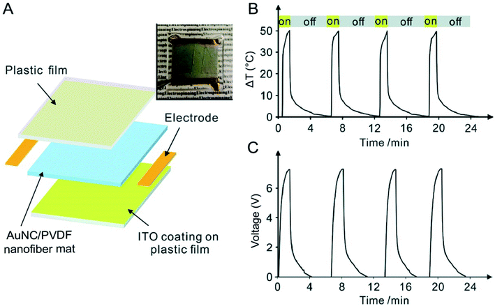 | ||
| Fig. 8 Use of AuNCs for light detection. (A) Schematic of a device based upon AuNC/PVDF nanofibers for light detection. The device was constructed from an indium tin oxide (ITO)-coated plastic film (upper layer), a nonwoven mat of AuNC/PVDF nanofibers (middle layer), and another ITO-coated plastic film (bottom layer). A photograph of this device is shown at the upper right corner. (B) Cyclic changes in temperature for the device when it was exposed to and blocked from an 808 nm laser at an irradiance of 0.2 W cm−2 and (C) the corresponding pyroelectric response. Reproduced from ref. 33 with permission from the Royal Society of Chemistry. Copyright 2018. | ||
4.2. Water evaporation
In a recent demonstration, it was shown that AuNCs hold great promise in applications such as seawater desalination and wastewater purification through photothermal evaporation of water.37 As illustrated in Fig. 9A, AuNCs with their LSPR peak tuned to 786 nm were incorporated into PVDF electrospun nanofibers and the nonwoven mat was then allowed to float on top of water to serve as the heating unit. Fig. 9B shows a scanning electron microscopy (SEM) image of the AuNC/PVDF nanofibers and a photograph (inset) of the as-fabricated mat. In comparison to the conventional techniques that are often operated to heat the bulk of a water source by placing the heating unit at the bottom of the container, the AuNC/PVDF mat naturally floated at the water/air interface due to the hydrophobicity of PVDF, allowing for continuous photothermal heating and localized evaporation of water at the interface. As shown by the infrared images in Fig. 9C, the interface temperature could be quickly increased to 96 °C when the AuNC/PVDF mat floating on water was irradiated with an 808 nm laser at an irradiance of 0.4 W cm−2, while the temperature remained at 28 °C for the mat made of PVDF nanofibers. The water evaporation rate of the AuNC/PVDF mat reached 3.64 ± 0.06 kg m−2 h−1 and remained stable over a period of 2 h (Fig. 9D). Taking an aqueous NaCl solution as an example of seawater, the hourly output of freshwater was 2.68 ± 0.04 L m−2 h−1 over an irradiation period of 5 h (Fig. 9E).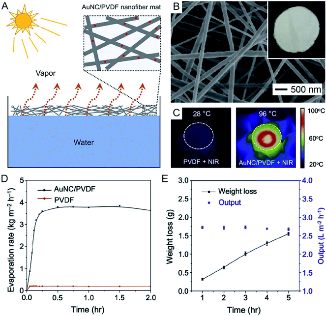 | ||
| Fig. 9 Use of AuNCs for water evaporation. (A) Schematic showing water evaporation through a nonwoven mat of AuNC/PVDF nanofibers. (B) SEM image and photograph (inset) of the AuNC/PVDF nanofiber mat. (C) Surface temperatures of the PVDF and AuNC/PVDF nanofiber mats after laser irradiation at an irradiance of 0.4 W cm−2 for 15 min. (D) Water evaporation rate as a function of time over an irradiation period of 2 h. (E) The weight loss and hourly output of water when the AuNC/PVDF nanofiber mat was used to evaporate an aqueous solution of NaCl over an irradiation period of 5 h. Reproduced from ref. 37 with permission from Elsevier. Copyright 2019. | ||
To make this new system based on AuNC/PVDF nanofibers more practical for solar-driven water evaporation, a mixture of three batches of AuNCs with LSPR peaks around 650, 740, and 970 nm was used to prepare the AuNC/PVDF nanofiber mat with strong absorption in the range of 500–1000 nm. In this case, the evaporation efficiency could reach 79.8% for the mat containing 0.10% of AuNCs (w/w) under solar irradiation over a period of 8 h. This efficiency is much higher relative to the conventional solar vapor generation systems (typically, with efficiencies in the range of 30–45%), where most of the energy is wasted to heat the water in the non-evaporation zone in the bulk.38,39 Another advantage of this system is that nanofiber-based mats can be produced on an industrial scale by switching to needleless electrospinning, making it ready for commercial application.40 For large-scale applications, the relatively high price of Au could become a major concern for the AuNC/PVDF nanofiber mats. This problem can be addressed by reducing the wall thickness of the AuNCs or incorporating non-expensive metals (e.g., Cu) into the wall to lower the usage of Au. The cost and efficiency can be further optimized by tuning the weight percentage of AuNCs in the nanofiber mat. On the other hand, the excellent thermal/chemical stability of AuNCs and PVDF would ensure their long-term and repeated use with robust performance.
4.3. Phase transition
The photothermal effect associated with AuNCs has also been used to trigger the phase-transition of thermo-responsive materials. The phase transition in these materials generally leads to tremendous changes in physiochemical properties, offering a powerful system for the fabrication of functional devices. In one demonstration, AuNCs were used to induce ferroelectric–paraelectric phase transition in PVDF thin films upon laser irradiation.41 As a well-known ferroelectric polymer, PVDF will undergo phase transition from ferroelectric (β or γ) to paraelectric (α) when heated to its ferroelectric Curie temperature at ca. 170 °C, a temperature very close to its melting point (177 °C).42,43 In a typical experiment, a AuNC/PVDF composite film was cast from a homogenous mixture of AuNCs and PVDF in dimethylformamide. When the composite film was exposed to an 808 nm laser at an irradiance of 1 W cm−2, the heat generated in the film caused the PVDF film to change from the ferroelectric β phase to the paraelectric α phase.41 Owing to the high photothermal conversion efficiency of AuNCs, the phase transition could be achieved in less than 10 s.More importantly, the AuNC-induced phase transition in PVDF could be further employed to create micropatterned ferroelectric domains by leveraging the spatiotemporal controllability of the NIR laser. Fig. 10A illustrates how to micropattern a ferroelectric film by directly using a laser beam as a writing pen to irradiate the AuNC/PVDF composite film mounted on a motorized x–y stage.41Fig. 10B shows the Raman mapping data, where the red color represents the β phase of PVDF while the green color corresponds to the α phase, demonstrating that only the irradiated regions were transited to the α phase. Representative Raman spectra in Fig. 10C and D further demonstrated that the β phase dominated the non-irradiated regions while the α phase dominated the laser-irradiated regions. The percentages of the α and β phases along the line marked in Fig. 10B indicated that the patterned β phase had a minimum feature size of around 20 μm (Fig. 10E). This kind of micropatterned ferroelectric film holds promise for application in NIR sensing and imaging.41
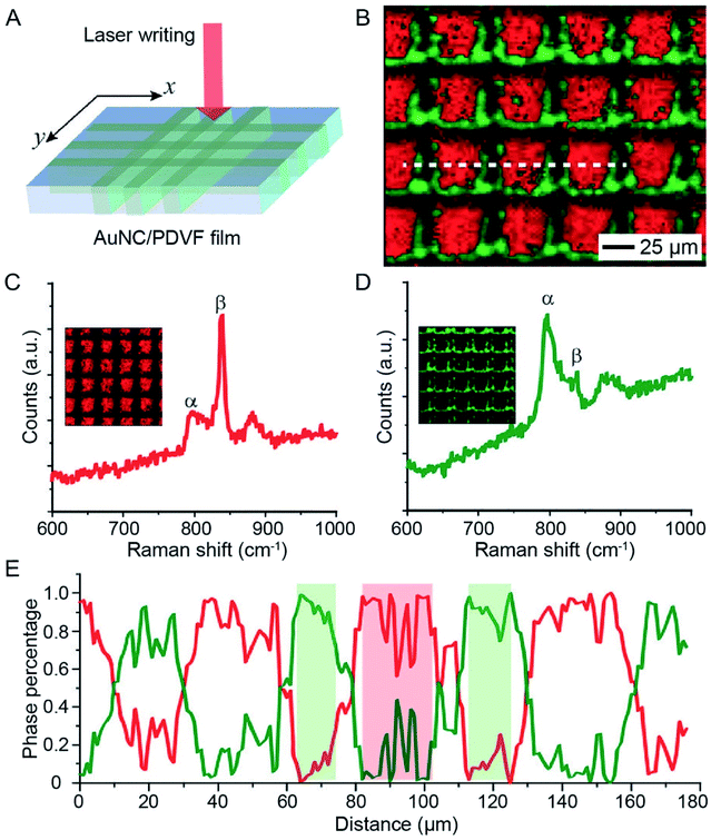 | ||
| Fig. 10 Use of AuNCs to trigger the phase transition in PVDF. (A) Schematic showing how to micropattern the phase of a AuNC/PVDF film by direct laser writing. (B) Raman mapping results of a AuNC/PVDF film after writing with a 785 nm laser. The motion of the sample was driven by a software-controlled motorized stage installed with the microscope. The red and green colors indicate the regions dominated by the β and α phases, respectively. (C and D) Representative Raman spectra of (C) the non-irradiated regions (dominated by the β phase) and (D) the laser-irradiated regions (dominated by the α phase). (E) Profile of the phase content along the dashed line marked in (B). Reproduced from ref. 41 with permission from Wiley-VCH. Copyright 2016. | ||
4.4. Controlled release
The AuNC-triggered phase-transition of thermo-responsive materials can also be utilized to manage the release of therapeutic agents used for disease treatment.44,45 Thermo-responsive materials can be applied as a coating around or a filler inside AuNCs to serve as an “on or off” gate to regulate the release of payloads under NIR irradiation. Among various types of thermo-responsive materials, phase-change materials (PCMs) based on natural fatty acids or fatty alcohols are most viable for biomedical applications owing to their easy preparation, low toxicity, biodegradability, and diversity.46,47 When used as a matrix material for the payload, PCMs can hold the payload inside AuNCs and help control its release in response to temperature rise and thus light irradiation.46,48 At the temperature below their melting point, PCMs exist in the solid phase to tightly hold the payload inside the AuNCs. When the local temperature is increased above the melting point by AuNC-enabled photothermal heating, the PCM will be melted to undergo a phase transition from solid to liquid, triggering quick release of the payload. In this way, the release profile of the payload from AuNCs can be easily manipulated by controlling the irradiance and/or duration of the laser.46 Notably, the hollow interior of AuNCs offers a high loading capacity for both the PCM and payload(s), helping minimize the use of AuNCs and thereby reducing the level of toxicity in vivo. At the same time, the multiple pores presented in the walls of AuNCs allow for quick loading and release of the payload(s).The AuNC/PCM system has been used for the controlled release and delivery of various types of therapeutic agents, including commercial anticancer drugs such as doxorubicin and inorganic compounds such as CaCl2 and H2SeO3.49–52 In one demonstration, CaCl2 was loaded into the cavity of AuNCs, with the PCM serving as a smart matrix, for killing cancer cells under NIR irradiation (Fig. 11A).51 Calcium ions (Ca2+) are an important component of various types of tissues and play critical roles in many metabolic processes. Normally, the concentration of Ca2+ ions inside cells is four orders of magnitude lower than the extracellular value (ca. 0.1 μM vs. 1–10 mM).53 A quick elevation in the intracellular concentration of Ca2+ ions will damage intracellular proteins, nucleic acids, and organelles, finally leading to cell death.54 To this end, the quick release of Ca2+ ions from AuNCs inside a cancer cell is able to kill the cell without involving other drugs. In a typical process, AuNCs were dispersed in an ethanol solution of CaCl2 and a PCM (lauric acid) for loading. The unloaded materials were removed through centrifugation and washing, followed by the addition of water to solidify the PCM and retain CaCl2 inside the cavity of AuNCs. The as-obtained CaCl2–PCM–AuNC particles were then uptaken by A549 cells, a human non-small-cell lung cancer cell, after a co-incubation process. Upon NIR irradiation, the heat generated by the AuNCs would melt the PCM, leading to the quick release of Ca2+ ions inside the cells. The sudden elevation in the intracellular Ca2+ concentration resulted in the disruption of the mitochondrial membrane and thus cell apoptosis (Fig. 11B). In comparison, without NIR irradiation, the Ca2+ ions were only released slowly as a result of the natural biodegradation of the PCM and did not cause measurable damage to the cells (Fig. 11C). For this system, it is worth mentioning that photothermal heating also occurs simultaneously, resulting in a combination therapy.51 It is worth pointing out that the thermo-responsive material can also be applied as a smart coating on the outer surface of AuNCs to enable controlled release. For example, modification of the outer surface of AuNCs with brushes of poly(N-isopropylacrylamide) or its derivatives, a type of thermally responsive polymer, through gold–thiolate chemistry could block the pores in the walls and keep the payloads inside the cavity.44 Upon photothermally heating to a temperature above its low critical solution temperature, the polymer brushes will collapse and expose the pores on the nanocages, causing the drug to release.
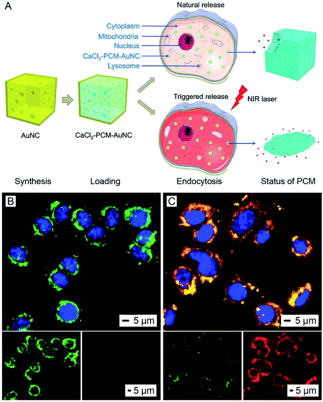 | ||
| Fig. 11 Use of AuNCs for controlling the release of a therapeutic agent. (A) Schematic illustration showing the NIR-triggered release of Ca2+ from a CaCl2–PCM–AuNC particle for killing a cancer cell. Upon NIR irradiation, the Ca2+ is quickly released with the melted PCM, leading to a sudden elevation in the intracellular Ca2+ concentration and thus cell apoptosis. Without NIR irradiation, the Ca2+ is only released slowly owing to the natural biodegradation of the PCM. (B and C) 5,5′,6,6′-Tetrachloro-1,1′,3,3′-tetraethylimidacarbocyanine iodide staining of A549 cells after incubation with the CaCl2–PCM–AuNCs for 6 h, followed by (B) irradiation with an 808 nm laser at an irradiance of 0.8 W cm−2 for 10 min or (C) no laser irradiation. The green fluorescence and red fluorescence indicate the loss and preservation of the mitochondrial membrane potential, respectively. The nuclei were stained to give a blue color. Reproduced from ref. 51 with permission from Wiley-VCH. Copyright 2018. | ||
4.5. Release and decomposition
The photothermal effect associated with AuNCs can also be employed to decompose organic compounds for the production of reactive species such as radicals. In one demonstration, 2,2′-azobis[2-(2-imidazolin-2-yl)propane] dihydrochloride (AIPH) was encapsulated in AuNCs for the generation of reactive radicals and thereby eradication of cancer cells (Fig. 12A).55 As a water-soluble azo compound commonly used as an initiator in radical polymerization, AIPH decomposes rapidly under thermal stimulation for the generation of alkyl radicals.56,57 The radicals can react with various cell components, leading to the apoptosis of cancer cells through damage to DNA and peroxidation of proteins and lipids. In a typical experiment, AIPH was loaded into the hollow interiors of AuNCs together with a PCM to obtain AIPH–PCM–AuNC particles. The PCM could protect AIPH from leaking into the aqueous medium while offering a precise control over the release profile to improve the therapeutic effect.46,55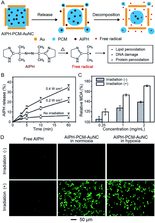 | ||
| Fig. 12 Use of AuNCs for controlling the release and photothermal decomposition of an organic compound. (A) Schematic illustration showing the controlled release of AIPH from a AuNC. The AIPH can be decomposed to generate free radicals upon photothermal heating. (B) Release profiles of AIPH from AIPH–PCM–AuNCs upon NIR irradiation at different irradiances. (C) MDA contents in RBCs when treated with AIPH–PCM–AuNCs at different concentrations in the presence/absence of NIR irradiation. (D) Detection of AIPH-induced ROS in A549 cells by 2′,7′-dichlorodihydrofluorescein diacetate staining. The cells were treated with AIPH (20 mg mL−1) or AIPH–PCM–AuNCs (AIPH: 20 mg mL−1) in normoxic and hypoxic culture media, respectively, for 2 h, followed by laser irradiation for 30 min. Reproduced from ref. 55 with permission from Wiley-VCH. Copyright 2017. | ||
Upon irradiation with a NIR laser, the PCM would be melted, leading to the release of AIPH. The released amount showed a positive correlation with the irradiance of the laser (Fig. 12B). In the meantime, AIPH would decompose to generate reactive alkyl radicals due to the temperature rise. Fig. 12C shows the content of methane dicarboxylic aldehyde (MDA, a product of lipid peroxidation) when red blood cells (RBCs) were incubated with AIPH–PCM–AuNC particles at different concentrations, demonstrating the generation of reactive radicals under NIR irradiation. More significantly, the generation of reactive species through thermal decomposition of AIPH was oxygen-independent, making this system suitable for cancer treatment under both normoxic and hypoxic conditions. The 2′,7′-dichlorodihydrofluorescein diacetate staining results in Fig. 12D showed that AIPH–PCM–AuNC particles could generate reactive oxygen species (ROS) in A549 cancer cells upon NIR irradiation under both normoxic and hypoxic conditions. The cell viability experiment further demonstrated that the radicals effectively were able to cause apoptosis and necrosis to A549 cells.
4.6. Photothermal therapy and potential image-guided treatment
Gold nanomaterials have received considerable attention in directly eradicating cancer cells through localized hypothermia.58,59 When the nanomaterials are accumulated in a solid tumor, external light irradiation can cause drastic increase in the local temperature to directly trigger thermal denaturing of proteins in the cells and coagulation of tissues, consequently causing irreversible damage to the lesion tissue. Tuning their LSPR peaks into the transparent window of soft tissues in the NIR region makes this technique particularly viable for the treatment of malignance occurring deeply below the skin. Furthermore, due to the bio-inertness of Au, its nanomaterials exhibit relatively good biocompatibility and photo-stability, making them particularly attractive for the photothermal destruction of solid tumors.6As for AuNCs, their hollow structure and large absorption cross section make it possible to reduce the amount of material introduced into the body while providing an adequate therapeutic effect. Encapsulation of therapeutic drugs into AuNCs will further allow for the combination therapy of photothermal treatment and temperature-controlled drug release. The in vivo pharmacokinetics including the biodistribution and tumor uptake of AuNCs can be easily tuned by varying their size, shape, and surface properties to improve their performance in photothermal therapy.26,27,60 For example, after modification of their surface with a monolayer of poly(ethylene glycol) (PEG) through the gold–thiolate interaction, AuNCs can be passively delivered to the tumor site because surface PEGylation allows for pro-longed circulation in the bloodstream and thus increases their accumulation in the tumor through the enhanced permeability and retention (EPR) effect.60 In addition, specific targeting moieties such as antibodies, peptides, and other types of ligands can also be conjugated to their surface to enable active, targeted delivery.49,61,62 More significantly, AuNCs or AuNC-based particles can be employed as contrast agents for two-photon or three-photon luminescence imaging, photoacoustic tomography, or positron emission tomography. As such, they can be potentially used for image-guided therapy to achieve enhanced treatment efficiency.62–64 This type of nanomaterial with multi-functional properties including imaging, drug delivery, controlled release, and photothermal therapy will be of great interest in nanomedicine.
5. Perspectives
5.1. Precision in terms of control
Despite the recent progress in the fabrication and utilization of AuNCs as photothermal agents, a number of challenges still need to be addressed before this class of nanomaterials can find use in real applications. Since the first report in 2002, how to realize a precise control over the size, shape, composition, wall thickness, and porosity of AuNCs has been a constant theme and research goal in terms of synthesis. For example, to cut down the usage of a scarce and expensive element such as Au, a seed-mediated growth method was developed to fabricate AuNCs with wall thicknesses as thin as a few atomic layers.18 For photothermal applications, AuNCs should be made with a large absorption cross section to offer a high photothermal conversion efficiency, and this can be achieved by reducing the size of the nanocages.11 Alternatively, AuNCs can be alloyed with another noble metal such as Pd or Pt known for strong absorption rather than scattering. In general, all the parameters associated with AuNCs need to be precisely controlled and optimized in order to meet the requirements of various applications. In biomedical applications, for example, a uniform distribution in terms of both size and shape is critical to control their transport behavior and performance in vivo.2,65 On the other hand, the size distribution needs to be broadened for applications such as water evaporation in order to better leverage the natural solar energy.375.2. New functionality
As an attractive feature of AuNCs, they can be engineered with specific functions through simple chemistry. A general approach is to modify their surface with functional molecules through the robust and well-established gold–thiolate linkage.66 For example, targeting peptides or proteins labeled with thiol groups can be easily attached to the surface of AuNCs to enable their capability in targeted delivery/imaging/therapy. Stimuli-responsive materials can also be deposited on the surface of AuNCs for the fabrication of systems capable of releasing payloads in response to specific stimuli.7,67 Alternatively, other metals can be post-deposited on the surface of AuNCs through seed-mediated growth to offer additional functions or capability. For example, radioactive 64Cu can be incorporated into the walls of AuNCs through the co-reduction of HAuCl4, CuCl2, and 64CuCl2 in the presence of AuNCs.64 The radiolabeled nanocages can then be employed as contrast agents for positron emission tomography (PET). Similarly, the nanocages can be endowed with catalytic ability through the deposition of precious metals such as Pd and Pt. A combination of the plasmonic properties of Au and Ag and the catalytic activities of other noble metals will lead to the development of plasmon-enhanced photo-catalysts.685.3. Scalable production
For most applications, one of the challenges is to produce AuNCs in large quantities while still maintaining a tight control over their size, shape, and optical response. A typical approach to increasing the production volume is to increase the volume of the reaction mixture. For example, the synthesis of Ag nanocubes could be scaled up by 10 times when moving from a 20 mL vial to a 250 mL flask. The entire batch of Ag nanocubes could then be placed in a 1000 mL flask and transformed into AuNCs through the titration of HAuCl4.69 However, due to the intrinsic difficulty in achieving thermal and compositional homogeneity over a large volume, it has been challenging to obtain products with high quality and good uniformity when the reaction volume is further scaled up. An alternative approach is to perform the reaction in a continuous-flow reactor.70,71 It has been demonstrated that both the Ag nanocubes and AuNCs could be generated in a droplet-based microreactor constructed from commercial polytetrafluoroethylene tubes.72,73 Using this new approach, the reaction parameters can be well controlled while the products are continuously generated. In addition, one can run multiple syntheses in parallel through the use of an array of flow reactors to further increase the scale of production without losing quality control. In addition, all the components, including the syringe, syringe pump, and polytetrafluoroethylene tube, used for the construction of a continuous-flow reactor are commercially available at relatively low costs, in large quantities, and with precisely controlled parameters.5.4. Photo-stability
Although AuNCs exhibit superior photo-stability compared to organic dyes, their stability under laser irradiation is still a concern considering that these particles can be quickly heated to very high temperatures by lasers with femto-, pico-, or nano-second pulse durations. As such, the nanocages may undergo photo-fragmentation, melting, or reshaping. The instability may result in alterations of the optical properties, therefore weakening their performance in various applications. For example, when AuNCs composed of 51% Au and 49% Ag (Fig. 13A and B) were exposed to a 750 nm laser with a pulse duration of 300 and a fluence of 30 mJ cm−2, they evolved into solid spheres (Fig. 13C).74 The energy-dispersive X-ray spectroscopy (EDX) elemental mapping results demonstrated that the spherical particles were made of a Au–Ag alloy with an elemental composition similar to that of pristine AuNCs (Fig. 13D). The morphological transformation of the AuNCs also altered their optical properties. As shown in Fig. 13E, when the AuNCs were exposed to the pulsed laser, the major LSPR peak of AuNCs at 750 nm decreased while a sharp peak at 460 nm representing the Au–Ag solid spheres appeared and increased with the increase of laser fluence. This study demonstrates that the photo-stability of AuNCs needs to be taken into consideration when exploring their applications. Methods capable of increasing the photo-stability of hollow and porous nanocrystals such as AuNCs will be of great interest. As mentioned above, the photo-stability of AuNCs is mainly limited by their shape instability which originates from the high specific surface energy of hollow nanocrystals. Thereby, the photo-stability of AuNCs can be possibly enhanced using an approach capable of reducing their specific surface energy, such as increasing the wall thickness or coating with another inert shell on the surface.75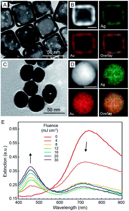 | ||
| Fig. 13 Stability of AuNCs under laser irradiation. (A) TEM image of Au–Ag nanocages and (B) EDX mapping results of a representative nanocage. (C) TEM image of the as-obtained pseudo-spherical, solid nanoparticles after 300 pulses at a laser fluence of 12 mJ cm−2 and (D) EDX mapping results of a representative solid nanoparticle. Scale bars in (B and D) are 25 nm. (E) UV-vis extinction spectra recorded from the aqueous suspensions of AuNCs after they had been irradiated for 300 pulses at different laser fluences. Reproduced from ref. 74 with permission from the Royal Society of Chemistry. Copyright 2019. | ||
In conclusion, we hope the readers will enjoy the synthetic methods, photothermal properties, and diverse applications of AuNCs discussed in this Perspective. Perhaps, they will be able to find inspiration to move this unique class of nanomaterials to the next level of success.
Conflict of interest
The authors declare no conflict of interest.Acknowledgements
This work was supported in part by startup funds from the Georgia Institute of Technology and grants from the National Institutes of Health (R01 CA138527 and R01 EB020050). We are grateful to our coworkers and collaborators for their invaluable contributions to this project.Notes and references
- Y. Sun, B. T. Mayers and Y. Xia, Nano Lett., 2002, 2, 481–485 CrossRef CAS
.
- B. Pang, X. Yang and Y. Xia, Nanomedicine, 2016, 11, 1715–1728 CrossRef CAS
.
- Y. Xia, W. Li, C. M. Cobley, J. Chen, X. Xia, Q. Zhang, M. Yang, E. C. Cho and P. K. Brown, Acc. Chem. Res., 2011, 44, 914–924 CrossRef CAS
.
- X. Xia and Y. Xia, Front. Phys., 2014, 9, 378–384 CrossRef
.
- Y. Yang, Q. Zhang, Z. Fu and D. Qin, ACS Appl. Mater. Interfaces, 2014, 6, 3750–3757 CrossRef CAS
.
- X. Yang, M. Yang, B. Pang, M. Vara and Y. Xia, Chem. Rev., 2015, 115, 10410–10488 CrossRef CAS
.
- S. Mura, J. Nicolas and P. Couvreur, Nat. Mater., 2013, 12, 991–1003 CrossRef CAS
.
- S. E. Skrabalak, L. Au, X. Li and Y. Xia, Nat. Protoc., 2007, 2, 2182–2190 CrossRef CAS
.
- J. Chen, F. Saeki, B. J. Wiley, H. Cang, M. J. Cobb, Z.-Y. Li, L. Au, H. Zhang, M. B. Kimmey, X. Li and Y. Xia, Nano Lett., 2005, 5, 473–477 CrossRef CAS
.
- S. E. Skrabalak, J. Chen, Y. Sun, X. Lu, L. Au, C. M. Cobley and Y. Xia, Acc. Chem. Res., 2008, 41, 1587–1595 CrossRef CAS
.
- X. Sun, J. Kim, K. D. Gilroy, J. Liu, T. A. F. König and D. Qin, ACS Nano, 2016, 10, 8019–8025 CrossRef CAS
.
- J. M. Li, Y. Yang and D. Qin, J. Mater. Chem. C, 2014, 2, 9934–9940 RSC
.
- S. Zhou, J. Li, K. D. Gilroy, J. Tao, C. Zhu, X. Yang, X. Sun and Y. Xia, ACS Nano, 2016, 10, 9861–9870 CrossRef CAS
.
- M. Yang, W. Wang, J. Qiu, M.-Y. Bai and Y. Xia, Angew. Chem., Int. Ed., 2019, 58, 17671–17674 CrossRef CAS
.
- Y. Sun, B. Mayers, T. Herricks and Y. Xia, Nano Lett., 2003, 3, 955–960 CrossRef CAS
.
- J. Zhang, S. A. Winget, Y. Wu, D. Su, X. Sun, Z. Xie and D. Qin, ACS Nano, 2016, 10, 2607–2616 CrossRef CAS
.
- L. Zhang, Y. Zhang, J. Ahn, X. Wang and D. Qin, Chem. Mater., 2019, 31, 1057–1065 CrossRef CAS
.
- Y. Yang, J. Liu, Z.-W. Fu and D. Qin, J. Am. Chem. Soc., 2014, 136, 8153–8156 CrossRef CAS
.
- Y. Wang, D. Wan, S. Xie, X. Xia, C. Z. Huang and Y. Xia, ACS Nano, 2013, 7, 4586–4594 CrossRef CAS
.
- J. Ahn, D. Wang, Y. Ding, J. Zhang and D. Qin, ACS Nano, 2018, 12, 298–307 CrossRef CAS
.
- J. Ahn, J. Kim and D. Qin, Nanoscale, 2020, 12, 372–379 RSC
.
- X. Sun, Y. Yang, Z. Zhang and D. Qin, Chem. Mater., 2017, 29, 4014–4021 CrossRef CAS
.
- X. Yang, K. D. Gilroy, M. Vara, M. Zhao, S. Zhou and Y. Xia, Chem. Phys. Lett., 2017, 683, 613–618 CrossRef CAS
.
- S. Bao, X. Yang, M. Luo, S. Zhou, X. Wang, Z. Xie and Y. Xia, Chem. Commun., 2016, 52, 12594–12597 RSC
.
- M. Yang, W. Wang, K. D. Gilroy and Y. Xia, Nano Lett., 2017, 17, 5682–5687 CrossRef CAS
.
- Y. Wang, Y. Liu, H. P. Luehmann, X. Xia, P. Brown, C. Jarreau, M. Welch and Y. Xia, ACS Nano, 2012, 6, 5880–5888 CrossRef CAS
.
- K. C. L. Black, Y. Wang, H. P. Luehmann, X. Cai, W. Xing, B. Pang, Y. Zhao, C. S. Cutler, L. V. Wang, Y. Liu and Y. Xia, ACS Nano, 2014, 8, 4385–4394 CrossRef CAS
.
- E. Hutter and J. H. Fendler, Adv. Mater., 2004, 16, 1685–1706 CrossRef CAS
.
- C. M. Cobley, J. Chen, E. C. Cho, L. V. Wang and Y. Xia, Chem. Soc. Rev., 2011, 40, 44–56 RSC
.
- X. Huang and M. A. El-Sayed, Alexandria J. Med., 2011, 47, 1–9 CrossRef
.
- X. Huang, S. Neretina and M. A. El-Sayed, Adv. Mater., 2009, 21, 4880–4910 CrossRef CAS
.
- Z. Qin and J. C. Bischof, Chem. Soc. Rev., 2012, 41, 1191–1217 RSC
.
- H. Li, T. Wu, M. Xie, Y. Shi, S. Shen, M. Zhao, X. Yang, L. M. Figueroa-Cosme, Q. Ke and Y. Xia, J. Mater. Chem. C, 2018, 6, 10263–10269 RSC
.
- S. E. Skrabalak, J. Chen, L. Au, X. Lu, X. Li and Y. Xia, Adv. Mater., 2007, 19, 3177–3184 CrossRef CAS
.
- E. C. Cho, C. Kim, F. Zhou, C. M. Cobley, K. H. Song, J. Chen, Z.-Y. Li, L. V. Wang and Y. Xia, J. Phys. Chem. C, 2009, 113, 9023–9028 CrossRef CAS
.
- J. Zeng, D. Goldfeld and Y. Xia, Angew. Chem., Int. Ed., 2013, 52, 4169–4173 CrossRef CAS
.
- T. Wu, H. Li, M. Xie, S. Shen, W. Wang, M. Zhao, X. Mo and Y. Xia, Mater. Today Energy, 2019, 12, 129–135 CrossRef
.
- P. Durkaieswaran and K. K. Murugavel, Renewable Sustainable Energy Rev., 2015, 49, 1048–1060 CrossRef
.
- A. E. Kabeel and S. A. El-Agouz, Desalination, 2011, 276, 1–12 CrossRef CAS
.
- J. Fang, H. Niu, H. Wang, X. Wang and T. Lin, Energy Environ. Sci., 2013, 6, 2196–2202 RSC
.
- J. Li, M. Yang, X. Sun, X. Yang, J. Xue, C. Zhu, H. Liu and Y. Xia, Angew. Chem., Int. Ed., 2016, 55, 13828–13832 CrossRef CAS
.
- P. J. Ratri and K. Tashiro, Polym. J., 2013, 45, 1107–1114 CrossRef CAS
.
- R. Hasegawa, Y. Takahashi, Y. Chatani and H. Tadokoro, Polym. J., 1972, 3, 600–610 CrossRef CAS
.
- M. S. Yavuz, Y. Cheng, J. Chen, C. M. Cobley, Q. Zhang, M. Rycenga, J. Xie, C. Kim, K. H. Song, A. G. Schwartz, L. V. Wang and Y. Xia, Nat. Mater., 2009, 8, 935–939 CrossRef CAS
.
- G. D. Moon, S.-W. Choi, X. Cai, W. Li, E. C. Cho, U. Jeong, L. V. Wang and Y. Xia, J. Am. Chem. Soc., 2011, 133, 4762–4765 CrossRef CAS
.
- J. Qiu, D. Huo and Y. Xia, Adv. Mater., 2020, 32, 2000660 CrossRef CAS
.
- J. Qiu, D. Huo, J. Xue, G. Zhu, H. Liu and Y. Xia, Angew. Chem., Int. Ed., 2019, 58, 10606–10611 CrossRef CAS
.
- D. C. Hyun, N. S. Levinson, U. Jeong and Y. Xia, Angew. Chem., Int. Ed., 2014, 53, 3780–3795 CrossRef CAS
.
- T. Sun, Y. Wang, Y. Wang, J. Xu, X. Zhao, S. Vangveravong, R. H. Mach and Y. Xia, Adv. Healthcare Mater., 2014, 3, 1283–1291 CrossRef CAS
.
- H. Cheng, D. Huo, C. Zhu, S. Shen, W. Wang, H. Li, Z. Zhu and Y. Xia, Biomaterials, 2018, 178, 517–526 CrossRef CAS
.
- Q. Chen, D. Huo, H. Cheng, Z. Lyu, C. Zhu, B. Guan and Y. Xia, Adv. Healthcare Mater., 2019, 8, 1801113 CrossRef
.
- L. Tian, N. Gandra and S. Singamaneni, ACS Nano, 2013, 7, 4252–4260 CrossRef CAS
.
- E. Carafoli, Annu. Rev. Biochem., 1987, 56, 395–433 CrossRef CAS
.
- S. Orrenius, B. Zhivotovsky and P. Nicotera, Nat. Rev. Mol. Cell Biol., 2003, 4, 552–565 CrossRef CAS
.
- S. Shen, C. Zhu, D. Huo, M. Yang, J. Xue and Y. Xia, Angew. Chem., Int. Ed., 2017, 56, 8801–8804 CrossRef CAS
.
- Y. Yoshida, N. Itoh, Y. Saito, M. Hayakawa and E. Niki, Free Radical Res., 2004, 38, 375–384 CrossRef CAS
.
- X.-Q. Wang, F. Gao and X.-Z. Zhang, Angew. Chem., Int. Ed., 2017, 56, 9029–9033 CrossRef CAS
.
- J. Chen, D. Wang, J. Xi, L. Au, A. Siekkinen, A. Warsen, Z.-Y. Li, H. Zhang, Y. Xia and X. Li, Nano Lett., 2007, 7, 1318–1322 CrossRef CAS
.
- J. Chen, C. Glaus, R. Laforest, Q. Zhang, M. Yang, M. Gidding, M. J. Welch and Y. Xia, Small, 2010, 6, 811–817 CrossRef CAS
.
- T. Sun, Y. S. Zhang, B. Pang, D. C. Hyun, M. Yang and Y. Xia, Angew. Chem., Int. Ed., 2014, 53, 12320–12364 CAS
.
- C. Wang, Y. Wang, L. Zhang, R. J. Miron, J. Liang, M. Shi, W. Mo, S. Zheng, Y. Zhao and Y. Zhang, Adv. Mater., 2018, 30, 1804023 CrossRef
.
- C. Kim, E. C. Cho, J. Chen, K. H. Song, L. Au, C. Favazza, Q. Zhang, C. M. Cobley, F. Gao, Y. Xia and L. V. Wang, ACS Nano, 2010, 4, 4559–4564 CrossRef CAS
.
- L. Tong, C. M. Cobley, J. Chen, Y. Xia and J.-X. Cheng, Angew. Chem., Int. Ed., 2010, 49, 3485–3488 CrossRef CAS
.
- M. Yang, D. Huo, K. D. Gilroy, X. Sun, D. Sultan, H. Luehmann, L. Detering, S. Li, D. Qin, Y. Liu and Y. Xia, ChemNanoMat, 2017, 3, 44–50 CrossRef CAS
.
- J. Chen, M. Yang, Q. Zhang, E. C. Cho, C. M. Cobley, C. Kim, C. Glaus, L. V. Wang, M. J. Welch and Y. Xia, Adv. Funct. Mater., 2010, 20, 3684–3694 CrossRef CAS
.
- J. Zhang, L. Mou and X. Jiang, Chem. Sci., 2020, 11, 923–936 RSC
.
- Y. Wang, M. S. Shim, N. S. Levinson, H.-W. Sung and Y. Xia, Adv. Funct. Mater., 2014, 24, 4206–4220 CrossRef CAS
.
- K. D. Gilroy, A. Ruditskiy, H.-C. Peng, D. Qin and Y. Xia, Chem. Rev., 2016, 116, 10414–10472 CrossRef CAS
.
- Q. Zhang, W. Li, L.-P. Wen, J. Chen and Y. Xia, Chem.–Eur. J., 2010, 16, 10234–10239 CrossRef CAS
.
- G. Niu, L. Zhang, A. Ruditskiy, L. Wang and Y. Xia, Nano Lett., 2018, 18, 3879–3884 CrossRef CAS
.
- G. Niu, A. Ruditskiy, M. Vara and Y. Xia, Chem. Soc. Rev., 2015, 44, 5806–5820 RSC
.
- L. Zhang, Y. Wang, L. Tong and Y. Xia, Langmuir, 2013, 29, 15719–15725 CrossRef CAS
.
- L. Zhang, Y. Wang, L. Tong and Y. Xia, Nano Lett., 2014, 14, 4189–4194 CrossRef CAS
.
- Z. D. Hood, K. P. Kubelick, K. D. Gilroy, D. Vanderlaan, X. Yang, M. Yang, M. Chi, S. Y. Emelianov and Y. Xia, Nanoscale, 2019, 11, 3013–3020 RSC
.
- S. Wen, X. Miao, G. Fan, T. Xu, L. Jiang, P. Wu, C. Ca and J. Zhu, ACS Sens., 2019, 4, 301–308 CrossRef
.
Footnote |
| † These authors contributed equally to the preparation of this article. |
| This journal is © The Royal Society of Chemistry 2020 |

