An iron foam acts as a substrate and iron source for the in situ construction of a robust transition metal phytate electrocatalyst for overall water splitting†
Xiaojuan
Chen
a,
Yan
Meng
a,
Taotao
Gao
a,
Jinmei
Zhang
b,
Xiaoqin
Li
c,
Hongyan
Yuan
*a and
Dan
Xiao
 *abc
*abc
aCollege of Chemical Engineering, Sichuan University, Chengdu 610065, PR China. E-mail: xiaodan@scu.edu.cn; yuan_hy@scu.edu.cn
bKey Laboratory of Green Chemistry and Technology, Ministry of Education, College of Chemistry, Sichuan University, Chengdu 610064, PR China
cInstitute of New Energy and Low-Carbon Technology, Sichuan University, Chengdu 610065, PR China
First published on 18th October 2019
Abstract
A metal iron foam benefiting from a three-dimensional skeleton and providing abundant active metal sites is an optimal alternative option for directly developing an economical and highly efficient water splitting electrocatalyst, but it is seldom reported. Herein, we adopted a one-step electrochemical erosion method to oxidize the iron foam surface and then, iron ions in situ chelated with bi-metallic phytates to afford stereo tri-metallic compounds. The introduction of the bimetal and phytates enabled the electrode to create more catalytic sites and construct a more complicated tridimensional structure, which enlarged the active surface area and improved the water splitting performance. Consequently, the as-prepared N7CF-phy electrode delivered higher current densities at lower overpotentials for the oxygen and hydrogen evolution reactions in 1 M KOH. After being assembled as an electrolyzer for overall water splitting, the electrodes still exerted a satisfying performance. Moreover, the sustained alternating chronopotentiometric measurements for N7CF-phy as both the oxygen and hydrogen evolution reaction (OER and HER) catalysts clarified the outstanding validity and robust durability.
Introduction
Designing electrocatalysts with a suitable economic benefit is the core aspect to lower the energy barriers and decrease the required overpotential from the thermodynamic requirement of 1.23 V vs. RHE.1,2 Pt, Ru or Ir-based noble metal materials are still the most efficient catalysts for HER and OER at present; however, their high cost and poor stability hinder their large-scale applications.3,4 Hence, exploring highly efficient, earth-abundant and stable bifunctional electrocatalysts with high activity for both HER and OER is a promising strategy to lower the cost and improve the energy transfer efficiency in the overall water splitting reaction.Generally, the design criteria for highly efficient water splitting catalysts involve the aspects of surface areas, amount of active sites, electrical conductivities and regulation of electronic/chemical properties.5 Metal iron with a high interfacial contact area is almost the cheapest metal on the Earth. It is also a great electron transfer medium and a promising conductive substrate to directly grow or deposit multi-metallic electrocatalysts similar to a carbon paper, carbon fiber or graphene foil. By in situ growing an active phase on conductive substrates, the treatment of the polymer binder and conducting reagent can be avoided, further decreasing the cost and simplifying the electrode preparation process.6 Moreover, the active phase on the substrate material can be fixed and dispersed well, which can tolerate a high work load for a long time owing to the better mass/electron transfer properties. Furthermore, this in situ strategy also tends to form a high mass loading of the active materials, thus affording more catalytic active sites.7 Finally, the incorporation/integration of foreign species in the self-supported electrode is very convenient for further improving the electrocatalytic performances in a synergistic way.9,10
In recent years, numerous reviews have summarized transition metal-based electrocatalysts for water splitting, especially those based on Ni, Co and Fe.8–13 In these reviews, countless articles have been used to exemplify the superior catalytic performance of the Co or Ni-based materials; in contrast, very few reports are about Fe-based materials except when merged as a dopant/impurity into Ni/Co-based catalysts to dramatically enhance their catalytic activity. Actually, metal iron is more abundant, cheaper and also less toxic than metal Co and Ni. In most of these articles, the amount of Fe in the compounds was always small and even in trace amounts. The introduction of optimal iron can enhance the catalytic activity in a transition metal system owing to the significant structural changes, effective conductivity increase and the significant surface reconstruction of the catalytic sites.9,14,15
Based on the above-mentioned information, we used a cost-efficient metal iron foam as the substrate and in situ generated polymetallic phytates via simple in situ electrochemical erosion at room temperature. The iron foam with a three-dimensional structure served as both a high-surface-area base and a slow-releasing iron precursor, which was oxidized at the oxidation potential. Once the Fe3+ cations were generated on the metal surface, the phytate groups captured Fe3+ immediately on account of the strong chelation capacity towards metals ions, further forming aggregate multimetallic phytates with Ni and Co ions. Due to the bare iron foam, the introduction of phytates remarkably promoted the catalytic activity and the subsequently incorporated Ni and/or Co ions could further bind with the other phosphate radicals to create more catalytic active sites and construct a more stereo structure. After the modification of the other transition metal ions and phytate groups, Fe-based N7CF-phy showed attractive OER and HER catalytic activities as well as a superior overall water splitting performance.
Experimental section
In situ synthesis of metal phytate electrodes
A three-electrode system was applied for the in situ formation process. The cleaned IFs (the real dimensions immersed in solution ≈1 cm−2), graphite plate and Ag/AgCl (saturated KCl solution) electrode served as the working electrode, the counter electrode and the reference electrode, respectively. Cyclic voltammetry was used to produce the electrodes with a potential window from −2.5 to 1.5 V vs. Ag/AgCl at a potential sweep rate of 20 mV s−1 for 8 cycles in freshly prepared metal-phy electrolyte solutions. The specifics for preparing the metal-phy solutions are as follows: 0.3 M sodium phytate (C6H6O24P6Na12: 85–90%, spray drying) solid was dissolved in 25 mL of distilled water, followed by stirring and sonication treatment. Then, different ratios of the mixed Ni–Co chemicals were added to the transparent sodium phytate solution to obtain the Ni–Co phytate solutions with a total concentration of 0.03 M. At last, the solutions were transported to a heating panel at 70 °C for 20 minutes. The as-prepared electrodes were named according to the molar ratios of Ni![[thin space (1/6-em)]](https://www.rsc.org/images/entities/char_2009.gif) :
:![[thin space (1/6-em)]](https://www.rsc.org/images/entities/char_2009.gif) Co; thus, the metal molar ratio of 7
Co; thus, the metal molar ratio of 7![[thin space (1/6-em)]](https://www.rsc.org/images/entities/char_2009.gif) :
:![[thin space (1/6-em)]](https://www.rsc.org/images/entities/char_2009.gif) 1 corresponds to N7CF-phy and F means Fe.
1 corresponds to N7CF-phy and F means Fe.
Characterizations
X-ray diffraction (XRD) analyses were conducted on a DX-2700 (Dandong Haoyuan) instrument equipped with Cu Kα radiation (k![[thin space (1/6-em)]](https://www.rsc.org/images/entities/char_2009.gif) =
=![[thin space (1/6-em)]](https://www.rsc.org/images/entities/char_2009.gif) 0.15418 nm) in the 2θ range of 20–80°. A NEXUS 670 spectrophotometer (Thermo Nicolet U.S.A.) was used to record the attenuated total reflection infrared spectrum (ATR-IR). Scanning electron microscopy (SEM) images were obtained on a field emission Hitachi S4800 microscope (Japan). The high-resolution transmission electron microscopy (HR-TEM) images and selected area electron diffraction (SAED) were recorded by FEI Tecnai G2 F20 S (U.S.A.) with an accelerating voltage of 200 kV. X-ray photoelectron spectra (XPS) were acquired with a Kratos AXIS ULTRA DLD photoelectron spectroscope (U.K.).
0.15418 nm) in the 2θ range of 20–80°. A NEXUS 670 spectrophotometer (Thermo Nicolet U.S.A.) was used to record the attenuated total reflection infrared spectrum (ATR-IR). Scanning electron microscopy (SEM) images were obtained on a field emission Hitachi S4800 microscope (Japan). The high-resolution transmission electron microscopy (HR-TEM) images and selected area electron diffraction (SAED) were recorded by FEI Tecnai G2 F20 S (U.S.A.) with an accelerating voltage of 200 kV. X-ray photoelectron spectra (XPS) were acquired with a Kratos AXIS ULTRA DLD photoelectron spectroscope (U.K.).
Electrochemical measurements
At an ambient temperature, we obtained all the electrochemical measurements using a three-electrode system with an Autolab PGSTAT 128 N potentiostat/galvanostat (Metrohm, Switzerland). The Hg/HgO and parallel positioned carbon plate were selected as the reference electrode and counter electrode, respectively. An applied potential window from 0 to +1.1 V vs. Hg/HgO was used for linear sweeping voltammograms (LSVs). Electrochemical impedance spectroscopy (EIS) tests in the frequency range of 10−2–105 Hz were performed for iR correction, which followed the calibration equation E(RHE) = 0.059 × pH + E(Hg/HgO) + 0.098. In addition, the RuO2 (Alfa Aesar, U.K.) and Pt/C (20%, Alfa Aesar, U.K.) electrodes were also prepared for comparison. After mixing RuO2 or Pt/C, 500 μL of distilled water-isopropyl alcohol (18![[thin space (1/6-em)]](https://www.rsc.org/images/entities/char_2009.gif) :
:![[thin space (1/6-em)]](https://www.rsc.org/images/entities/char_2009.gif) 7, v/v), and 10 μL of Nafion solution (5 wt%, Dupont, U.S.A.), the mixed inks were dropped onto NF with a mass loading of 8 mg cm−2.
7, v/v), and 10 μL of Nafion solution (5 wt%, Dupont, U.S.A.), the mixed inks were dropped onto NF with a mass loading of 8 mg cm−2.
Result and discussion
As shown in Fig. 1, the cleaned NF is oxidized at the applied potentials and chelated with the surrounding metal phytate groups at the same time to synthesize N7CF-phy in one step. The electrochemical curves in Fig. S1b† show the redox process of the Fe substrate to Fe2+/Fe3+ in the F-phy system. By comparison, the curves in Fig. S1a† are more intricate due to the joining of the Co and Ni ions. The bubbles of hydrogen and oxygen can be observed apparently when the potentials become higher and lower in both images, which increases the possibility of enlarging the specific area of the active materials. The apparent color change of NF indicated the successful growth of N7CF-phy (Fig. S2†). Some properties before and after the eletrodeposition of the iron foam can be found in Table S1.†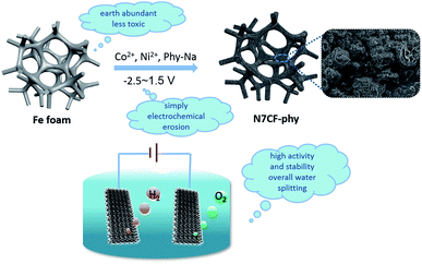 | ||
| Fig. 1 Schematic illustration of the electrochemical growth processes for N7CF-phy and the morphology of the obtained materials as well as the utilization for overall water splitting. | ||
At first, we investigated the surface morphology of N7CF-phy by SEM. From Fig. 2a, we can observe that the active materials are uniformly distributed on the surface of the iron foam along the three-dimensional skeleton. The high-resolution SEM image in Fig. 2b indicates that the active materials consist of granule congeries and wrinkled structures clad inside, which is different from the smooth surface of F-phy (Fig. S4†). This unique structure is very constructive for increasing specific surface areas and exposing a large amount of accessible active sites. Then, a TEM test was used to verify the amorphous active material in a certain aggregation state, as shown in Fig. 2c. Obviously ordered lattice fringes cannot be found in the HR-TEM image (Fig. 2d), indicating the poor crystallinity of N7CF-phy. The vague halo ring in the SAED image and the only detected iron peaks in the XRD pattern (Fig. S5†) also demonstrated this quality.
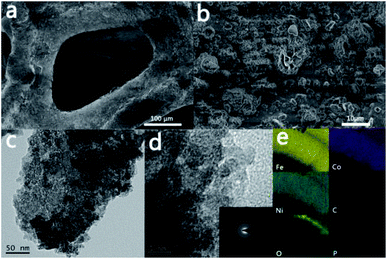 | ||
| Fig. 2 (a and b) SEM, (c) TEM, (d) HR-TEM, (inset of d) SAED and (e) EDS elemental mapping images of N7CF-phy. | ||
Besides, we explored the chemical composition and electronic states of the elements in the near surface region of the as-prepared electrode by ATR-IR and XPS. Regarding the ATR-IR analysis (Fig. S6a†), the peaks at 1647, 1525, 1390, 900–1031 and 730–845 cm−1 are attributed to the O–P–O deformation, C–H ring bending, P–O stretching, P–O–C symmetrical frequencies and P–O–(H or metal) stretching, indicating the structure of the phytates.16–19 The XPS images in Fig. 3a successfully prove that N7CF-phy comprises the Ni, Co, Fe, C, O and P elements, which is in agreement with the SEM/EDS elemental mapping results (Fig. 2e). More specifically, the corresponding high-resolution XPS spectra of the selected elements are shown in Fig. 3b–f. In the C 1s XPS spectrum (Fig. 3b), the peaks at 286.7 and 288.2 eV correspond to the C–O and C–C bonds, indicating the structure of the phytate radical.20,21 The P 2p (Fig. 3c) and O 1s spectra (Fig. S6b†) further demonstrate the presence of metal phytate compounds based on the peaks at 132.9 and 531.4 eV, which belong to the phosphate group.22,23 In Fig. 3d, the presence of the Fe substrate is verified at a binding energy of 706.6 eV. The peaks at the binding energies of 710.9 and 718.8 eV for Fe 2p3/2 indicate that the majority of the Fe substrates are oxidized to Fe3+.24,25 In the Co 2p spectrum (Fig. 3e), the peak at a binding energy of 781.4 eV can be ascribed to Co 2p3/2 of Co2+ and its shakeup satellite peak is at 785.8 eV.22,26,27 For Ni 2p (Fig. 3f), the main peak with binding energy at 856.1 eV belongs to Ni 2p2/3 of Ni2+ and the satellite peak is located at 861.7 eV.26,28,29
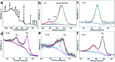 | ||
| Fig. 3 XPS pattern of N7CF-phy and the corresponding element spectra of C 1s, P 2p, Fe 3p, Co 2p, and Ni 2p. | ||
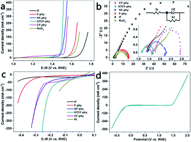
Afterwards, we evaluated the water oxidation activities of the metal phytate electrodes with different metal proportions, bare IF and commercial RuO2/NF, as shown in Fig. 4a and S7a.† Obviously, the introduction of the Ni and Co ions dramatically improved the catalytic performances of the metal-phy electrode. This showed that N7CF-phy with an optimal ratio (Ni![[thin space (1/6-em)]](https://www.rsc.org/images/entities/char_2009.gif) :
:![[thin space (1/6-em)]](https://www.rsc.org/images/entities/char_2009.gif) Co = 7) also outperformed commercial RuO2, single metallic F-phy and bi-metallic NF-phy/CF-phy with respect to activities. More specifically, as shown in Table S2,† N7CF-phy exhibits high catalytic activities with 20 and 200 mA cm−2 at the low overpotentials of 224 and 275 mV, respectively, and it is superior to most metal-based electrocatalysts. Furthermore, the smallest Tafel slope for N7CF-phy at 31 mV dec−1 among the electrodes (Fig. S8a; also listed in Table S2†) suggested favorable catalytic reaction kinetics and a rapid current growth within the unit potential range. Then, EIS measurements were recorded at a potential of 1.52 V vs. RHE; they are depicted in Fig. 4b along with circuit model fitting analysis. The equivalent circuit includes a solution resistance (Rs), a constant phase element (CPE) and a charge transfer resistance (Rct). From the recorded semicircles, it is easy to observe that the Rct value for N7CF-phy is obviously smaller than the others, thus suggesting a much faster electron transfer during the electrocatalytic reaction. The electrochemically active surface areas (ECSA) can be estimated from the electrical double-layer capacitance (Cdl) of different electrodes owing to the proportion reaction among them (Cdl ∝ ν × ECSA).30,31 As shown in Fig. S9,† the slopes of the curves represent the capacitance and obviously, the low-cost iron-based ternary metal phytate demonstrates a superior double-layer capacitance at 7.798 mF cm−2, indicating a larger surface area and conduction due to the sufficient exposure of the electroactive sites.
Co = 7) also outperformed commercial RuO2, single metallic F-phy and bi-metallic NF-phy/CF-phy with respect to activities. More specifically, as shown in Table S2,† N7CF-phy exhibits high catalytic activities with 20 and 200 mA cm−2 at the low overpotentials of 224 and 275 mV, respectively, and it is superior to most metal-based electrocatalysts. Furthermore, the smallest Tafel slope for N7CF-phy at 31 mV dec−1 among the electrodes (Fig. S8a; also listed in Table S2†) suggested favorable catalytic reaction kinetics and a rapid current growth within the unit potential range. Then, EIS measurements were recorded at a potential of 1.52 V vs. RHE; they are depicted in Fig. 4b along with circuit model fitting analysis. The equivalent circuit includes a solution resistance (Rs), a constant phase element (CPE) and a charge transfer resistance (Rct). From the recorded semicircles, it is easy to observe that the Rct value for N7CF-phy is obviously smaller than the others, thus suggesting a much faster electron transfer during the electrocatalytic reaction. The electrochemically active surface areas (ECSA) can be estimated from the electrical double-layer capacitance (Cdl) of different electrodes owing to the proportion reaction among them (Cdl ∝ ν × ECSA).30,31 As shown in Fig. S9,† the slopes of the curves represent the capacitance and obviously, the low-cost iron-based ternary metal phytate demonstrates a superior double-layer capacitance at 7.798 mF cm−2, indicating a larger surface area and conduction due to the sufficient exposure of the electroactive sites.
We know that sole Fe materials have unsatisfactory hydrogen evolution properties. However, after in situ electrochemical treatment, the iron-based metal-phy electrodes expressed outstanding HER catalytic performances in 1.0 M KOH (Fig. 4c and S7b†). N7CF-phy achieved current densities of −50 and −200 mA cm−2 at the overpotentials of 145 and 229 mV, respectively. This was comparable to that of many previously reported noble metal-free HER electrocatalysts in alkaline media including recently developed Co (Fe, or Ni)-based catalysts as well as some MP-based catalysts (Table S3†). Moreover, we recorded the CV data between −0.68 and 2.0 V (vs. RHE) to verify that N7CF-phy was a highly capable bifunctional HER and OER catalyst (Fig. 4d). The faradaic efficiency, which is always used to evaluate the turnover ability of a catalyst for electricity-to-gas applications, was calculated by the actual test and theoretical gas production ratio based on the current density. As shown in Fig. S10,† the efficiencies for oxygen and hydrogen evolution are both approximately 100%.
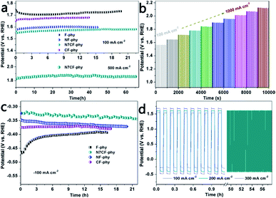
The OER and HER stabilities were tested using long-term chronopotentiometry under large current densities (Fig. 5a and c and Table S2†). In comparison, N7CF-phy presented outstanding OER and HER durability at ±100 mA cm−2 for more than 22 hours and it was superior to other Fe-based metal-phy electrodes. Even at the high current density of 500 mA cm−2, it still maintained its catalytic activity for more than 65 hours, indicating its wonderful practical application potential. In addition, a multi-step chronopotentiometric measurement demonstrated potential changes from 100 to 1000 mA cm−2 (Fig. 5b). The stable responses indicated its marvelous mass transport performance (OH– diffused inward and gas bubbles diffused outward), conductivity and mechanical robustness. Furthermore, as shown in the curves in Fig. 5d, N7CF-phy can be alternatively used as both an OER catalyst and an HER catalyst to conduct alternating chronopotentiometric tests for clarifying the outstanding validity and robust durability at the sustaining current densities of ±100, ±200 and ±300 mA cm−2. Obviously, the potential gradient was enhanced with the increase in current densities; especially, no obvious changes were observed after continuous 500 cycles of high current density at ±200 mA cm−2, strongly suggesting the true bifunctional properties of this Fe-based metal phytate material.
The SEM images of this electrode after long-term large current density anodic and cathodic electrolysis (Fig. S11†) show that the morphologies of the electrode both collapse to a certain extent. Therefore, to further elaborate the transformation of the compositions accompanied by the morphology change, high-resolution XPS analyses were conducted. The peak fitting analysis of C 1s in Fig. S12d and S13d† suggests that there are almost no changes in the binding energies of –C–C and –C–O after the durability test, which means that the structure of phytates is maintained after the oxidation or reduction reaction for a long time. In contrast, both the P 2p peaks almost disappeared (Fig. S12f and S13f†). Regarding the spectra of Co 2p, Ni 2p and Fe 2p (Fig. S12 and S13†), the positions for the binding energy slightly shifted compared with the spectra before the durability test. Then, combined with the variation in O 1s in Fig. S12e,† which appears at 530.9 eV due to the metal–oxygen bonds, we can figure out that the surface of the electrode gradually transformed to high-value metal oxides after long-term continuous water oxidation.22,23,32 The Raman spectra in Fig. S15† also verify that metal oxides and hydroxides are formed on the surface of the electrode. Similar results can also be observed for numerous TM-based electrocatalysts like TM phosphides, TM sulfides and TM carbides. Actually, the metal oxides/hydroxides/oxyhydroxides are the real catalytic sites and the incorporation of metal phytates or other TM-based catalysts is expected to improve conductivity and surface area and create more accessible active sites, thus enhancing the catalytic performances.33 The metal ratio of the post-oxidation electrode is shown in Fig. S16,† which is not very different from the original. Similarly, for O 1s in Fig. S13e,† the peaks at 529.7 and 531.0 eV belong to the metal–oxygen and metal–hydroxyl bonds, respectively.22,34 During the long-term continuous hydrogen evolution, metal oxides/hydroxides were formed on the surface of N7CF-phy, which was a probable reason for the vanished P 2p peaks. In addition, the 3D structure also suffered destruction to some extent owing to the leaching of P after the durability experiments.35 Combined with the analysis of the literature and the Raman analysis in Fig. S15,† the MOx/M or M(OH)x/3dM interfaces in alkaline HER always show their significance. H2O split to generate OH− at first and then attached on the positively charged M species in MOx, while the adjacent metal sites promoted H adsorption to release H2 on the electrode.36 Additionally, the existence of M(OH)x facilitated the dissociation of water and the synthesis of hydrogen intermediates.37,38 Therefore, the synergistic effect among the metal species with different valences was due to the outstanding hydrogen evolution performances. The real metal ratio of the metal ions after the HER durability experiment is shown in Fig. S17.†
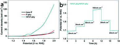
In the end, two-electrode configurations for overall water splitting were devised by using the catalysts as both the anode and the cathode. It can be found in Fig. 6a and Table S4† that the cell voltages used to obtain 10 mA cm−2 are only 1.55 V for N7CF-phy//N7CF-phy, 1.86 V for F-phy//F-phy and 1.84 V for IF//IF. Besides, a chronopotentiometry test was performed from 20 to 100 mA cm−2 for 18 h (Fig. 6b). The potential basically stabilized at 1.69 V when the onset current density was 20 mA cm−2; when the current density increased to 30, 50 and 100 mA cm−2, the cell voltages increased accordingly and rapidly stayed steady. These results proved the promising bi-functional properties of N7CF-phy//N7CF-phy for overall water splitting in an alkaline solution.
Conclusions
Overall, a cheap iron foam was used as a substrate and an involved reagent took part in the in situ electrochemical erosion process for preparing a wonderful bi-functional electrocatalyst towards water splitting. The introduction of phytates facilitated the construction of three-dimensional networks and the subsequent joining of the Co and Fe ions further created more catalytic active sites in the reaction. Moreover, the resistance and surface area were also improved to some extent. The step current experiment applied under continuous current densities of ±100, ±200 and ±300 mA cm−2 also verified the outstanding validity and robust durability of N7CF-phy. Consequently, the wonderful catalytic activities and excellent durability for OER and HER indicate that this material will make some contributions for promoting the transition from the lab bench to large-scale applications in energy conversion and storage systems.Conflicts of interest
There are no conflicts to declare.Acknowledgements
This work was supported by the National Nature Science Foundation of China (21777108) and the Fundamental Research Funds for the Central Universities (20826041A4031).References
- A. Sivanantham and S. Shanmugam, Appl. Catal., B, 2017, 203, 485–493 CrossRef CAS.
- Y. Zheng, Y. Jiao, M. Jaroniec and S. Z. Qiao, Angew. Chem., Int. Ed., 2015, 54(1), 52–65 CrossRef CAS PubMed.
- C. Tang, N. Cheng, Z. Pu, W. Xing and X. Sun, Angew. Chem., Int. Ed., 2015, 127(32), 9483–9487 CrossRef.
- X. Zheng, X. Han, H. Liu, J. Chen, D. Fu, J. Wang, C. Zhong, Y. Deng and W. Hu, ACS Appl. Mater. Interfaces, 2018, 10(16), 13675–13684 CrossRef CAS PubMed.
- X. Shang, B. Dong, Y. Chai and C. Liu, Sci. Bull., 2018, 63, 853–876 CrossRef CAS.
- G. Chen, T. Ma, Z. Liu, N. Li, Y. Su, K. Davey and S. Qiao, Adv. Funct. Mater., 2016, 26(19), 3314–3323 CrossRef CAS.
- Z. Yan, H. Sun, X. Chen, H. Liu, Y. Zhao, H. Li, W. Xie, F. Cheng and J. Chen, Nat. Commun., 2018, 9(1), 2373 CrossRef PubMed.
- L. Han, S. Dong and E. Wang, Adv. Mater., 2016, 28(42), 9266–9291 CrossRef CAS PubMed.
- M. I. Jamesh, J. Power Sources, 2016, 333, 213–236 CrossRef CAS.
- P. Li, Z. Jin, Y. Qian, Z. Fang, D. Xiao and G. Yu, ACS Energy Lett., 2019, 4(8), 1793–1802 CrossRef CAS.
- M. I. Jamesh and X. Sun, J. Power Sources, 2018, 400, 31–68 CrossRef CAS.
- F. Lu, M. Zhou, Y. Zhou and X. Zeng, Small, 2017, 13(45), 1701931 CrossRef PubMed.
- A. Li, Y. Sun, T. Yao and H. Han, Chem.–Eur. J., 2018, 24(69), 18334–18355 CrossRef CAS PubMed.
- D. Friebel, M. W. Louie, M. Bajdich, K. E. Sanwald, Y. Cai, A. M. Wise, M. J. Cheng, D. Sokaras and T. C. Weng, J. Am. Chem. Soc., 2015, 137(3), 1305–1313 CrossRef CAS PubMed.
- T. Gao, C. Zhou, Y. Zhang, Z. Jin, H. Yuan and D. Xiao, J. Mater. Chem. A, 2018, 6(43), 21577–21584 RSC.
- J. Chen, Y. Song, D. Shan and E. H. Han, Corros. Sci., 2013, 74, 130–138 CrossRef CAS.
- F. Pan, X. Yang and D. Zhang, Appl. Surf. Sci., 2009, 255(20), 8363–8371 CrossRef CAS.
- U. P. Rodrigues-Filho, S. Vaz, M. P. Felicissimo, M. Scarpellini, D. R. Cardoso, R. C. Vinhas, R. Landers, J. F. Schneider, B. R. McGarvey and M. L. Andersen, J. Inorg. Biochem., 2005, 99(10), 1973–1982 CrossRef CAS PubMed.
- J. Torres, N. Veiga, J. S. Gancheff, S. Domínguez, A. Mederos, M. Sundberg, A. Sánchez, J. Castiglioni, A. Díaz and C. Kremer, J. Mol. Struct., 2008, 874(1–3), 77–88 CrossRef CAS.
- X. Cui, Q. Li, Y. Li, F. Wang, G. Jin and M. Ding, Appl. Surf. Sci., 2008, 255(5), 2098–2103 CrossRef CAS.
- X. Long, J. Li, S. Xiao, K. Yan, Z. Wang, H. Chen and S. Yang, Angew. Chem., Int. Ed., 2014, 126(29), 7714–7718 CrossRef.
- P. Li, Z. Jin, J. Yang, Y. Jin and D. Xiao, Chem. Mater., 2016, 28(1), 153–161 CrossRef CAS.
- Y. Li and C. Zhao, Chem. Mater., 2016, 28(16), 5659–5666 CrossRef CAS.
- K. Yan, T. Lafleur, J. Chai and C. Jarvis, Electrochem. Commun., 2016, 62, 24–28 CrossRef CAS.
- X. F. Lu, L. F. Gu, J. W. Wang, J. X. Wu, P. Q. Liao and G. R. Li, Adv. Mater., 2017, 29(3), 1604437 CrossRef PubMed.
- A. L. Wang, H. Xu and G. R. Li, ACS Energy Lett., 2016, 1(2), 445–453 CrossRef CAS.
- Y. Zhang, T. Gao, Z. Jin, X. Chen and D. Xiao, J. Mater. Chem. A, 2016, 4(41), 15888–15895 RSC.
- X. Lu and C. Zhao, Nat. Commun., 2015, 6, 6616 CrossRef CAS PubMed.
- B. Zhang, C. Xiao, S. Xie, J. Liang, X. Chen and Y. Tang, Chem. Mater., 2016, 28(19), 6934–6941 CrossRef CAS.
- Y. Li and C. Zhao, Chem. Mater., 2016, 28(16), 5659–5666 CrossRef CAS.
- P. Li, Z. Jin and D. Xiao, J. Mater. Chem. A, 2014, 2(43), 18420–18427 RSC.
- X. Zhang, J. Xiao, X. Zhang, Y. Meng and D. Xiao, Electrochim. Acta, 2016, 191, 758–766 CrossRef CAS.
- X. Wang, H. Chen, Y. Xu, J. Liao, B. Chen, H. Rao, D. Kuang and C. Su, J. Mater. Chem. A, 2017, 5(15), 7191–7199 RSC.
- Z. Q. Liu, G. F. Chen, P. L. Zhou, N. Li and Y. Z. Su, J. Power Sources, 2016, 317, 1–9 CrossRef CAS.
- D. Yang, L. Cao, L. Feng, J. Huang, K. Kajiyoshi, Y. Feng, Q. Liu, W. Li, L. Feng and G. Hai, Appl. Catal., B, 2019, 257, 117911 CrossRef CAS.
- J. Wei, M. Zhou, A. Long, Y. Xue, H. Liao, C. Wei and Z. Xu, Nano-Micro Lett., 2018, 10(4), 75 CrossRef CAS PubMed.
- N. Danilovic, R. Subbaraman, D. Strmcnik, K. C. Chang, A. Paulikas, V. Stamenkovic and N. M. Markovic, Angew. Chem., Int. Ed., 2012, 124(50), 12663–12666 CrossRef.
- D. Strmcnik, P. P. Lopes, B. Genorio, V. R. Stamenkovic and N. M. Markovic, Nano Energy, 2016, 29, 29–36 CrossRef CAS.
Footnote |
| † Electronic supplementary information (ESI) available. See DOI: 10.1039/c9se00348g |
| This journal is © The Royal Society of Chemistry 2020 |

