Theory and practice of origami in science
Christian D.
Santangelo
ab
aSyracuse University, Syracuse, NY 13244, USA. E-mail: cdsantan@syr.edu
bUniversity of Massachusetts, Amherst, MA 01003, USA
First published on 6th November 2019
Abstract
No longer just the purview of artists and enthusiasts, origami engineering has emerged as a potentially powerful tool to create three dimensional structures on disparate scales. Whether origami (and the closely related kirigami) engineering can emerge as a useful technology will depend crucially on both fundamental theoretical advances as well as the development of further fabrication tools.
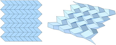
Origami and kirigami are ancient art forms that aim to turn a flat sheet of paper into a three dimensional sculpture (Fig. 1). Because of new fabrication methods to design responsive materials, recent years have seen a surge of interest in using origami-related ideas in engineering to create three dimensional structures from thin, and initially flat, films.1–4 The needs of engineering have similarly led to renewed interest in understanding the fundamental physics and mathematics that underlies folding.
 | ||
| Fig. 1 (a) An origami fold pattern is constructed from a single continuous sheet while (b) a kirigami fold pattern with an excised face whose free, internal edges can be “glued” together when folded. | ||
Two factors have led to this interest. First, mathematical tools have led to new and powerful ways to design complex sculptures.5–7 The fold pattern of these sculptures are, at least in part, designed by a computer, and it has become clear that the world of origami is far richer than one might have been led to believe. In principle, any shape can be approximated from a single flat sheet.7 Second, new fabrication techniques have enabled the creation of “architected materials,” composite materials whose local structure is designed to lead to new effective properties at longer ranges.8–10 The incorporation of responsive materials into these architectural structures, from swelling hydrogels to liquid crystal and dielectric elastomers, allows us to shape differential strains within structures and thereby get them to fold into three dimensions.3,11,12
Success could revolutionize the manufacture of devices from macroscopic scales down to millimeter or even micron scales. Because origami structures are patterned while flat, self-folding devices are amenable to lithographic or roll-to-roll processing. This suggests that, with the right processing and materials, self-folding origami structures can be produced in large batches. Since the mechanical principles driving self-folding are universal and scale-free,13,14 the techniques developed can be applied, at least in principle, on a variety of materials and processes. One of the holy grails of soft matter research has been to develop techniques to self-assemble complex three-dimensional structures. Self-folding origami is a potential alternative to these traditional self-assembly pathways; by placing functional elements on the initially flat structures and folding them into three dimensions, one could achieve the same functionality.
Quite a bit of progress in origami engineering has so far followed an “art-mimetic” approach: one borrows a design from the world of origami art and adapts it to a new material and new applications.15,16 This is, of course, a fruitful way to proceed, especially considering the wealth of experience from the world of origami art. Despite the wealth of examples of this type, this perspective will take a somewhat idiosyncratic view of origami science. I will argue that fulfilling the full promise of origami engineering will require theoretical and experimental progress, proceeding in tandem. Following this way of thinking, I will orient the discussion from the side of origami mathematics.17
1 How should scientists define origami?
The traditional conception of what defines origami is not necessarily applicable to science. A traditional origami artist might impose arbitrary rules on themselves – for example, fold a single sheet of paper without cutting – which is far too rigid to be useful from the perspective of science. Similarly, two techniques that an artist might describe as “origami” may lead to very different underlying mathematics. Here we will take a different approach. In order to avoid the inevitable splitting of hairs that comes with the making of strict definitions, I will provide four assumptions, none of which can be met experimentally, but which can serve the basis to unite many types of origami and kirigami research into a broader field of mathematics that can inform how we think about origami structures. To that end, here are four characteristics of ideal origami:1. An origami structure is constructed from vertices, edges and faces which are zero-, one-, or two-dimensional respectively. This means, in principle, that vertices are point-like and edges and faces are infinitely thin. This assumption is certainly not satisfied in practice and some effort has gone in to understanding what happens when these assumptions are lifted. For example, there has been theoretical work trying to understand the folding of “thick” origami.18–21
2. Origami edges do not curve and faces do not bend. Again, this is probably violated in practice, and excludes work on curved folds,22–24 and face bending is particularly easy to see in an origami structure.8 Nevertheless, if the folds remain straight then any interior face can only bend along a face diagonal anyway; this suggests that face bending origami can, in principle, be modeled by introducing auxiliary folds across the diagonals. Thus, there is little loss of generality with such an assumption.
3. Edges do not stretch. While not true experimentally, in the limit that the ratio of bending to stretching stiffnesses goes to zero, this assumption is not difficult to satisfy approximately. In practice, this can be achieved when the thickness is small and any external forces are sufficiently weak.
4. There is no gluing, cutting, or rearranging of folds and vertices. While we allow origami to explicitly allow the possibility of holes and cutting, we will exclude “gluing.” This gluing assumption is often explicitly lifted by “kirigami”,25 though this usage kirigami does not at all conform to how artists use those words and does not always fit the scientific literature either. On the other hand, this assumption is fairly easy to achieve experimentally.
No experiments can meet assumptions 1–4, though many do come close and can, at least, be accurately modeled by making these assumptions. For example, real paper is not infinitely thin, and experience trying to fold a particularly tricky piece of origami demonstrates that paper can crumple and deform in confounding ways. Yet, paper is very thin compared to the lateral dimensions of most origami, and fold lengths and faces do tend to be rigid under careful folding. In that sense, it is clear that there are conditions in which real origami is at least close to ideal origami.
The above assumptions also contain a few surprising cases that one might not traditionally think of as origami. As one example, triangular meshes, which are used to model elastic membranes, when elastically thin so that they bend far more easily than stretch, can be an example of an origami mechanism. As a second example, note that there is no assumption that vertices should be flat. In some versions of kirigami, one generates vertices with nonzero Gaussian curvature by removing wedges of material and reattaching the paper along the newly cut seams.25 The process of cutting and gluing is excluded from assumption 4, but the structures formed after gluing and cutting are not. It is, perhaps, a subtle point: assumption 4 is there to exclude origami that changes its structure dynamically as it deforms.
Among flat, ideal origami structures, two cases have been very well-studied. The first is quad origami, in which all faces are quadrilaterals and each vertex has four folds associated to it. This case is a generalization of the celebrated Miura ori fold pattern.26 Four-fold vertices have precisely one degree of freedom and the relationships between the dihedral angles can be determined analytically. The second important case is triangulated origami, in which all faces are triangles but vertices can have an arbitrary number of folds emerging from them. In this case, faces are always planar and the length constraints associated with folds ensure that the planar angles between adjacent folds at each vertex stay the same. This allows one to understand the kinematics of triangulated origami in terms of the kinematics of linkages.
The assumptions 1–4 bring the study of origami squarely within a venerable historical context going back at least as far as Cauchy27 and J. C. Maxwell,28,29 who have studied the rigidity of frameworks and linkages. Indeed, origami and kirigami mechanisms conforming to the assumptions above can sometimes be mapped directly to the mechanics of a specific class of frameworks. This allows us to bring some powerful mathematical tools to bear on the mechanics of origami. Similarly, others have explored the folding of crystalline lattices30–33 and highlighted some fundamental connections between random folding and spin systems34,35 and coloring problems.36 These two bring additional insights to the kinematics of origami structures and can be used to shed light on the behavior of real origami systems that approximate assumptions 1–4.
1.1 Infinitesimal isometries
We start our analysis of the motions of origami by assuming all faces are triangles. This is, in some sense, the “base” case: any origami fold pattern can be obtained by selectively rigidifying some of the folds of a triangulated fold pattern. As will become clear, we must distinguish the case in which the origami fold pattern is flat from the case in which the initial origami structure is not planar. Because the faces are triangular, preserving the lengths of the edges necessarily preserved the interior angles of the faces. Supposing that an edge joins vertex n to vertex m, the kinematics of the origami are completely determined by a system of equations – one for each edge – of the form| (Xn − Xm)2 = Lnm2, | (1) |
| Ru = 0. | (2) |
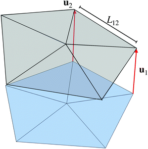 | ||
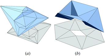
| Fig. 2 Origami can be represented as a mechanical linkage with vertices, indexed by integer n, displaced by un. The blue origami is flat while the gray is folded. | ||
How many degrees of freedom does a generic, triangulated origami structure support? To make an appropriate count, we must distinguish between vertices and edges in the interior, which are actual vertices and folds of the origami fold pattern, and those on the boundary. Let Vi and Vb denote the number of interior and boundary vertices respectively, and let Ei and Eb denote the number of interior and boundary edges. Then a simple counting argument shows that the solution space of eqn (2) is generically of dimension Vb + 3. To obtain this count, we need two relations. The first is Euler's formula for a planar graph, F − Eb − Ei + Vb + Vi = 1. The second is the relation for triangulated origami that each face abuts three edges but that, consequently, internal edges are double counted. Therefore, 3F = 2Ei + Eb. Thus, the number of parameters needed to place Vb + Vi vertices in three dimensions is 3Vb + 3Vi = 3 + 3Eb + 3Ei − (2Ei + Eb) = 3 + 2Eb + Ei. Finally, the dimension of the configuration space is given by D = 3Vb + 3Vi − Ei − Eb since each edge provides one constraint, leaving D = 3 + Eb = 3 + Vb since Eb = Vb for a polygon. However, since there are six rigid body motions, this leaves a configuration space of foldings with Vb − 3 dimensions.
When the origami is flat, this naive count appears wrong. In fact, in that case, there are Vb + Vi + 3 possible motions since each interior vertex can be displaced vertically without changing the edge lengths to first order. It turns out, however, that there are Vi quadratic constraints in this case,37 strongly suggesting D = Vb + 3 is still the correct dimension of the configuration space. This is an upper bound for the dimension of the origami configuration space, in general. If we proceed to rigidify a single fold in order to make a face with more than three sides, we must then add a linear constrain to the infinitesimal motions, reducing the number of degrees of freedom by one.
1.2 Nonlinear approaches to modeling
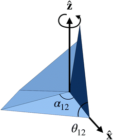
An alternative approach to modeling is to consider constraints on a single origami vertex.38,39 Consider, for example, the intersection of a single vertex with an imaginary sphere whose center is placed on the vertex. This intersection traces out a spherical polygon on the sphere's surface. Now align one of the folds with the![[x with combining circumflex]](https://www.rsc.org/images/entities/b_char_0078_0302.gif) axis and the face joining fold 1 to fold 2 with the xy-plane. To get from the first to the second fold, one must then rotate the vertex about the ẑ axis by the first interior angle, α12, so that the second fold is now aligned with the
axis and the face joining fold 1 to fold 2 with the xy-plane. To get from the first to the second fold, one must then rotate the vertex about the ẑ axis by the first interior angle, α12, so that the second fold is now aligned with the ![[x with combining circumflex]](https://www.rsc.org/images/entities/b_char_0078_0302.gif) axis. A second rotation can be performed about the
axis. A second rotation can be performed about the ![[x with combining circumflex]](https://www.rsc.org/images/entities/b_char_0078_0302.gif) axis by the fold angle θ2. The composition of these rotations must then bring us back to our original configuration. Specifically,
axis by the fold angle θ2. The composition of these rotations must then bring us back to our original configuration. Specifically,R(θ1,![[x with combining circumflex]](https://www.rsc.org/images/entities/b_char_0078_0302.gif) )R(αN1,ẑ)⋯R(θ3, )R(αN1,ẑ)⋯R(θ3,![[x with combining circumflex]](https://www.rsc.org/images/entities/b_char_0078_0302.gif) )R(α23,ẑ)R(θ2, )R(α23,ẑ)R(θ2,![[x with combining circumflex]](https://www.rsc.org/images/entities/b_char_0078_0302.gif) )R(α12,ẑ) = 1, )R(α12,ẑ) = 1, | (3) |
![[n with combining circumflex]](https://www.rsc.org/images/entities/b_char_006e_0302.gif) ) denotes the rotation matrix rotating by an angle θ about axis
) denotes the rotation matrix rotating by an angle θ about axis ![[n with combining circumflex]](https://www.rsc.org/images/entities/b_char_006e_0302.gif) . This method is closely allied with the analysis of origami single vertex rigidity using spherical trigonometry (Fig. 3).40
. This method is closely allied with the analysis of origami single vertex rigidity using spherical trigonometry (Fig. 3).40
A system of constraints of this type allow one to generate necessary (but not sufficient) conditions for an origami fold pattern to be foldable, and provides information about the relationships between folds.38 More broadly, however, it turns out that determining whether an origami fold pattern is foldable (without tearing or bending) at all is NP-hard.41 And suppose an origami fold pattern can be folded. Then the number of ways of folding the origami structure is generically exponential in the number of vertices.37,42,43
For triangulated origami, for example, the infinitesimal isometries all have the form of vertical displacements of the Vb + Vi vertices. Denoting the vertical displacement of the nth vertex by hn, Bryan Chen and I have shown that the heights satisfy a system of quadratic equations,37
 | (4) |
2 Origami design
Some of the most important scientific and mathematical work on understanding what is possible with origami comes from artists and mathematicians. There are several important results that highlight both the potential and challenges of origami design. It is known that a single sheet of paper can be folded into any polyhedron, as will be described in the next section. This is the basis behind the statement that any shape can be approximated. However, the number of folds required can be quite large; there is no sense in which the computer program produces a design that is optimal. Design within a more restricted set of patterns is, however, possible.2.1 Designing shapes
The design of fold patterns that produce specific, desired shapes is one of the oldest in origami.44 Computation design tools have been developed by several authors, most notably Robert Lang, who developed a program called “Tree Maker”.5,45 Tree Maker allows a user to design an origami base – essentially by specifying a tree graph that can serve as part of the body plan of a more complex origami design. The program then proceeds to provide a fold pattern which the artist can use to fold the basic body plan, after which the artist adds additional folds to further shape the structure.One might wonder whether one can actually fold a single sheet of paper into any shape. In fact, this question has been answered in the affirmative. First, Demaine has proven that it is possible to approximate any voxelated shape by folding alone using a single, universal fold pattern.46 The technique takes advantage of an origami design motif called box pleating.47 Second, further work by Tachi and followed up by Demaine have demonstrated a computer program, the “origamizer,” which takes as input a polyhedron and returns a fold pattern that can be used to fold into the given polyhedron.7,48
Neither of these design tools are practical, however. In particular, because they are approximating polyhedra with vertices that have Gaussian curvature using a sheet whose vertices do not, some of the area of the original sheet must be tucked away and hidden, essentially by forcing the origami faces to nearly overlap, and there is no sense in which the computations are optimal from the point of view of minimizing hidden area. Secondly, techniques such as box pleating for producing voxelated designs are computationally hard.47
One possible approach to simplifying the origami design problem is to limit the search space to a smaller family of possible fold patterns. These methods are typically variations on the Miura ori design49 (see Fig. 4). Designs based on quadrilateral faces, such as the Miura ori, are usually called “quad meshes.” The difficulty with quad meshes as a design motif is that they are not necessarily rigidly foldable. The counting arguments of the previous section show this: each vertex has four folds and, consequently, one nontrivial degree of freedom. Yet, each closed loop of folds must be compatible in order for a folding motion to be possible. The high symmetry of the regular Miura ori pattern in Fig. 4 introduces enough redundancy that all of these additional constraints can be satisfied. For arbitrary meshes, however, they could not generically be. One solution is to introduce folds along a diagonal of each face. For an infinite structure, however, there are still only enough degrees of freedom to balance the constraints; the generic case is still rigid.
To rectify this, Tachi has developed equations that can determine whether quad mesh origami is, indeed, rigidly foldable.51 These developments, coupled with geometric considerations, have allowed several groups to design new quad mesh origami. In this vein, Dudte et al. and others have shown that quad mesh origami can be designed to fold into a great variety of curvatures by designing a precise spatial variation in the quad mesh origami.50,52,53 Some designs are shown in Fig. 5.
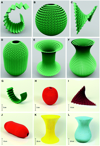 | ||
| Fig. 5 Reproduced from ref. 50 with permission from Springer Nature, copyright 2016. Note that, in this work, quadrilateral faces are allowed to stretch slightly and bend but that this can often be accommodated by triangulated the design first. | ||
2.2 Designing mechanical response
In contrast to shape, even less is known about designing the mechanical response of origami structures.10,54,55 Many origami tesselations are naturally auxetic,1 as is the classic Miura ori tesselation, whose Poisson ratio can be tuned by the fold geometry.13,14 Even for a fixed fold geometry, different folding paths can lead to different, and tunable, fold configurations.56 For example, the Miura ori with different configurations of “pop-through” defects have a rationally tunable mechanical response.8,57Beyond this, there is a great deal of experience, from traditional origami artists, on how different fold patterns respond to deformations. Designs exist for bistable and self-locking origami,58 and some design approaches exist within certain classes of origami structures.59 While there have been some successes using topology optimization to design mechanical response,60 but we have only begun to scratch the surface of what is possible.
3 Self-folding
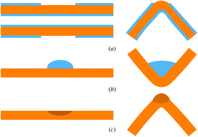
The driving impetus for the emergence of origami as a tool of engineering comes from the fabrication of structures that can fold themselves up from an initially flat, thin film. There seems to be two main mechanisms for driving the self-folding of origami. One can draw the folds to bend by adding small droplets of an evaporating or contracting liquid, or one can fabricate materials that develop differential strains cross their thickness. Because mechanisms of differential strain are, essentially, scale-free, materials have been developed on disparate length scales from the human-scale to a scale of tens of microns (Fig. 6).The mechanism for self-folding origami devices is primarily one of differential growth. This is often achieved by bonding together materials with different proclivities toward expansion under changes in temperature, pH, or some other change of environmental conditions. This has taken the form of graphene–glass bimorphs,61 polymer trilayers with a swellable hydrogel sandwiched between two stiffer layers,11 shape memory composites,62 or contracting solder.2 In most of these cases, the folding generates a preferred fold angle on several of the folds.
In the typical case of modeling the self-folding process, one usually assumes that each fold acts as a torsional spring,
 | (5) |
 | (6) |
 | (7) |
![[small theta, Greek, macron]](https://www.rsc.org/images/entities/i_char_e0c9.gif) = H0w and the fold stiffness kf is proportional to the fold length, L. In real materials, one expects deviations from this simple form.63,64
= H0w and the fold stiffness kf is proportional to the fold length, L. In real materials, one expects deviations from this simple form.63,64
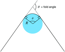 | ||
| Fig. 7 Folding a Hookean elastic sheet at fixed width leads to an energy in the form of a torsional spring. | ||
The best understood cases of self folding are single vertices and, especially, vertices associated with four folds. In that case, we know that there are precisely two distinct fold branches and one can obtain the fold angles in closed form.65,66 Since there are four folds, we can plot the fold angles of three of them as a function of a fourth (Fig. 8). If one allows for the faces to pass through each other, the two branches are actually connected to each other and only become distinct when self-intersections are disallowed (though proving this can be a challenge67,68). One can superimpose, on Fig. 8, the energy of eqn (5), whose equi-energy surfaces are ellipsoids. The origami will fold along one branch or the other so long as the energy decreases along that branch. One can now formulate the question: when is the energy decreasing only along one origami branch? The answer, according to Tachi and Hull, is that the gradient of the energy in the flat state should be perpendicular to all the “wrong” branches69 rather than being directed along the correct branch. In fact, this arises from the fact that the branch structure near the flat state is always invariant under flipping the sign of all the fold angles (after all, flip the origami over). If the gradient isn't perpendicular to a branch, the energy necessarily must decrease along one direction of the branch. The gradient of the fold energy is
 | (8) |
![[small theta, Greek, macron]](https://www.rsc.org/images/entities/i_char_e0c9.gif) f to tune the gradient.
f to tune the gradient.
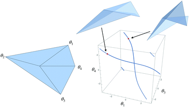 | ||
| Fig. 8 Three fold angles of a degree four vertex. Note that the calculated angles are periodic in the interval (−2π,2π] and the origami structure can, in principle, self intersect. | ||
This is, unfortunately, asking a lot. For triangulated origami with no holes, the number of folds is
| Ei = Vb + 3Vi. | (9) |
Yet this may not be the end of the story. In many cases, the branches are governed by individual vertex buckling. Recently, Hayward et al.70 have found that origami folding can be controlled by engineering vertices that are biased to buckle upward or downward independently of the folds. Stern et al.71 have also found methods that can control the bifurcations of mechanical linkages and, in particular, origami. These new results show clearly a need for further analysis in order to understand and fine-tune the folding of origami.
4 Where are the emerging challenges?
As we have progressed, we also have developed a better picture of the most difficult challenges that must be solved before this becomes a technology. There are, first of all, the challenges we know. Given the proliferation of folding pathways for even simple origami designs in tandem with the difficulty of determining if a pattern is even foldable, new methods to ensure robust folding will certainly need to be developed, and the interplay between energetics and kinematics will need to be better understood. And while some progress has been made in designing fold patterns that achieve targeted three dimensional shapes, much remains unsolved.Beyond this, little is understood in how fold patterns determine the effective mechanical properties of folded figures. The same isometric motions that allow origami to fold also ensure that there is a pathway toward easy unfolding. To deal with this, packagers either use adhesives (which experience tells us can be a struggle to open) or mechanisms that lock, for example through flaps. The degree of geometrical control required to do this is still beyond what any experiments have achieved. To do this would likely require dynamically altering how a system folds, perhaps by activating folds sequentially.72 Only then could one create a structure that folds on its own and, subsequently, becomes rigid.
There are also unknown challenges. Most examples of self-folding origami structures are still at the “proof-of-principle” stage. The pathway to get from this stage to one where folding is fast and the resulting mechanism performs robustly remains unclear, though some work has been attempted along these directions. How easily can self-folding materials be coupled with the kinds of materials one builds electronic or optical devices from ref. 73? Can origami mechanical structures carry a load? To what extent can the folding pathways be programmable or, even, reprogrammable?74 What kind of yield could one expect and how complex could the origami be?
Finally, and importantly, more realistic models of origami folding will need to be developed to better understand the behavior and buckling of origami devices in the real world. Here I am envisioning something between the idealized mathematical approaches that have been mostly studied until now and more accurate but computationally expensive finite-element simulations.75,76 How would a typical origami structure deform? What parts of the structure determine the rigidity, for example?
The field of origami is still in its infancy, yet it could revolutionize the manufacture and fabrication of three dimensional structures. We are at the point now where, perhaps, we could start asking some of these more difficult questions.
Conflicts of interest
There are no conflicts to declare.Acknowledgements
I acknowledge funding through the National Science Foundation DMR-1822638.Notes and references
- M. Schenk and S. D. Guest, Origami 5: Fifth International Meeting of Origami Science, Mathematics, and Education, 2011, pp. 291–304.
- V. B. Shenoy and D. H. Gracias, MRS Bull., 2012, 37, 847–854 CrossRef CAS.
- S. Felton, M. Tolley, E. Demaine, D. Rus and R. Wood, Science, 2014, 345, 644–646 CrossRef CAS.
- E. A. Peraza-Hernandez, D. J. Hartl, R. J. Malak Jr and D. C. Lagoudas, Smart Mater. Struct., 2014, 23, 094001 CrossRef.
- R. J. Lang, Treemaker 4.0: A program for origami design, 1998 Search PubMed.
- E. D. Demaine, M. L. Demaine and J. Ku, Origami5: Proceedings of the 5th International Conference on Origami in Science, Mathematics and Education (OSME2010), 2011, pp. 449–454.
- E. D. Demaine and T. Tachi, 33rd International Symposium on Computational Geometry (SoCG 2017), 2017.
- J. L. Silverberg, A. A. Evans, L. McLeod, R. C. Hayward, T. Hull, C. D. Santangelo and I. Cohen, Science, 2014, 345, 647–650 CrossRef CAS.
- E. Boatti, N. Vasios and K. Bertoldi, Adv. Mater., 2017, 29, 1700360 CrossRef.
- C. Lv, D. Krishnaraju, G. Konjevod, H. Yu and H. Jiang, Sci. Rep., 2014, 4, 5979 CrossRef CAS.
- J.-H. Na, A. A. Evans, J. Bae, M. C. Chiappelli, C. D. Santangelo, R. J. Lang, T. C. Hull and R. C. Hayward, Adv. Mater., 2015, 27, 79–85 CrossRef CAS.
- J. Mu, C. Hou, H. Wang, Y. Li, Q. Zhang and M. Zhu, Sci. Adv., 2015, 1, e1500533 CrossRef.
- Z. Y. Wei, Z. V. Guo, L. Dudte, H. Y. Liang and L. Mahadevan, Phys. Rev. Lett., 2013, 110, 215501 CrossRef CAS.
- A. A. Evans, J. L. Silverberg and C. D. Santangelo, Phys. Rev. E: Stat., Nonlinear, Soft Matter Phys., 2015, 92, 013205 CrossRef.
- B. J. Edmondson, L. A. Bowen, C. L. Grames, S. P. Magleby, L. L. Howell and T. C. Bateman, ASME 2013 conference on smart materials, adaptive structures and intelligent systems, 2013, p. V001T01A027.
- T. A. Evans, R. J. Lang, S. P. Magleby and L. L. Howell, R. Soc. Open Sci., 2015, 2, 150067 CrossRef.
- C. D. Santangelo, Annu. Rev. Condens. Matter Phys., 2017, 8, 165–183 CrossRef.
- T. Tachi, Origami, 2011, 5, 253–264 Search PubMed.
- Y. Chen, R. Peng and Z. You, Science, 2015, 349, 396–400 CrossRef CAS.
- B. J. Edmondson, R. J. Lang, S. P. Magleby and L. L. Howell, ASME 2014 International Design Engineering Technical Conferences and Computers and Information in Engineering Conference, 2014, p. V05BT08A054.
- J. S. Ku and E. D. Demaine, J. Mech. Robot., 2016, 8, 031003 CrossRef.
- M. A. Dias, L. H. Dudte, L. Mahadevan and C. D. Santangelo, Phys. Rev. Lett., 2012, 109, 114301 CrossRef.
- J. Mitani, Origami, 2011, 5, 437–447 Search PubMed.
- M. A. Dias and C. D. Santangelo, EPL, 2012, 100, 54005 CrossRef CAS.
- T. Castle, Y. Cho, X. Gong, E. Jung, D. M. Sussman, S. Yang and R. D. Kamien, Phys. Rev. Lett., 2014, 113, 245502 CrossRef PubMed.
- M. Schenk and S. D. Guest, Proc. Natl. Acad. Sci. U. S. A., 2013, 110, 3276–3281 CrossRef CAS.
- A. L. Cauchy, J. Ec. Polytech., 1813, 16, 87–99 Search PubMed.
- J. C. Maxwell, London, Edinburgh Dublin Philos. Mag. J. Sci., 1864, 27, 294–299 CrossRef.
- J. C. Maxwell, London, Edinburgh Dublin Philos. Mag. J. Sci., 1864, 27, 250–261 CrossRef.
- P. Di Francesco and E. Guitter, EPL, 1994, 26, 455 CrossRef.
- M. Bowick, P. Di Francesco, O. Golinelli and E. Guitter, Nucl. Phys. B, 1995, 450, 463–494 CrossRef.
- E. N. Cirillo, G. Gonnella and A. Pelizzola, Phys. Rev. E: Stat. Phys., Plasmas, Fluids, Relat. Interdiscip. Top., 1996, 53, 1479 CrossRef CAS PubMed.
- P. Di Francesco and E. Guitter, Phys. Rep., 2005, 415, 1–88 CrossRef.
- M. Assis, Phys. Rev. E, 2018, 98, 032112 CrossRef CAS.
- K. Roychowdhury, D. Z. Rocklin and M. J. Lawler, Phys. Rev. Lett., 2018, 121, 177201 CrossRef CAS.
- P. Di Francesco, Random matrix models and their applications, 2001, vol. 40, p. 111 Search PubMed.
- B. G.-g. Chen and C. D. Santangelo, Phys. Rev. X, 2018, 8, 011034 CAS.
- S.-M. Belcastro and T. C. Hull, Linear Algebra Appl., 2002, 348, 273–282 CrossRef.
- T. Tachi, Proceedings of the International Association for Shell and Spatial Structures (IASS) Symposium, 2010, pp. 458–460.
- K. Miura, Research of Pattern Formation, KTK Scientific Publishers, Tokyo, Japan, 1989, pp. 91–102 Search PubMed.
- H. Akitaya, E. D. Demaine, T. Horiyama, T. C. Hull, J. S. Ku and T. Tachi, 2018, arXiv preprint arXiv:1812.01160.
- M. Stern, M. B. Pinson and A. Murugan, Phys. Rev. X, 2017, 7, 041070 Search PubMed.
- S. Waitukaitis and M. van Hecke, Phys. Rev. E, 2016, 93, 023003 CrossRef.
- K. Kasahara, Creative origami, Japan Publications, 1977 Search PubMed.
- R. J. Lang, Proceedings of the twelfth annual symposium on Computational geometry, 1996, pp. 98–105.
- N. M. Benbernou, E. D. Demaine, M. L. Demaine and A. Ovadya, Origami5: Proceedings of the 5th International Conference on Origami in Science, Mathematics and Education, 2010, pp. 405–420.
- H. A. Akitaya, K. C. Cheung, E. D. Demaine, T. Horiyama, T. C. Hull, J. S. Ku, T. Tachi and R. Uehara, Japanese Conference on Discrete and Computational Geometry and Graphs, 2015, pp. 167–179.
- T. Tachi, IEEE Trans Vis. Comput. Graph., 2009, 16, 298–311 Search PubMed.
- K. Miura, Proposition of pseudo-cylindrical concave polyhedral shells, Institute of Space and Aeronautical Science, University of Tokyo, 1969 Search PubMed.
- L. H. Dudte, E. Vouga, T. Tachi and L. Mahadevan, Nat. Mater., 2016, 15, 583 CrossRef CAS.
- T. Tachi, Journal of the International Association for Shell and Spatial Structures, 2009, 50, 173–179 Search PubMed.
- H. Nassar, A. Lebée and L. Monasse, Proc. R. Soc. A, 2017, 473, 20160705 CrossRef CAS.
- M. Konaković-Luković, J. Panetta, K. Crane and M. Pauly, ACM Trans. Graph., 2018, 37, 106 CrossRef.
- V. Brunck, F. Lechenault, A. Reid and M. Adda-Bedia, Phys. Rev. E, 2016, 93, 033005 CrossRef CAS.
- S. Li, H. Fang, S. Sadeghi, P. Bhovad and K.-W. Wang, Adv. Mater., 2019, 31, 1805282 CrossRef.
- P. P. Pratapa, K. Liu and G. H. Paulino, Phys. Rev. Lett., 2019, 122, 155501 CrossRef CAS.
- H. Fang, S. Li, H. Ji and K. Wang, Phys. Rev. E, 2017, 95, 052211 CrossRef.
- S. Kamrava, D. Mousanezhad, H. Ebrahimi, R. Ghosh and A. Vaziri, Sci. Rep., 2017, 7, 46046 CrossRef CAS.
- F. Wang, H. Gong, X. Chen and C. Chen, Sci. Rep., 2016, 6, 33312 CrossRef CAS.
- A. Gillman, K. Fuchi, A. Cook, A. Pankonien and P. R. Buskohl, ASME 2018 International Design Engineering Technical Conferences and Computers and Information in Engineering Conference, 2018, p. V05BT07A059.
- M. Z. Miskin, K. J. Dorsey, B. Bircan, Y. Han, D. A. Muller, P. L. McEuen and I. Cohen, Proc. Natl. Acad. Sci. U. S. A., 2018, 115, 466–470 CrossRef CAS.
- M. T. Tolley, S. M. Felton, S. Miyashita, D. Aukes, D. Rus and R. J. Wood, Smart Mater. Struct., 2014, 23, 094006 CrossRef.
- F. Lechenault, B. Thiria and M. Adda-Bedia, Phys. Rev. Lett., 2014, 112, 244301 CrossRef CAS.
- T. Jules, F. Lechenault and M. Adda-Bedia, Soft Matter, 2019, 15, 1619–1626 RSC.
- S. Waitukaitis, R. Menaut, B. G.-G. Chen and M. van Hecke, Phys. Rev. Lett., 2015, 114, 055503 CrossRef.
- E. D. Demaine, M. L. Demaine, D. A. Huffman, T. C. Hull, D. Koschitz and T. Tachi, Proceedings of IASS Annual Symposia, 2016, pp. 1–10.
- I. Streinu and W. Whiteley, Japanese Conference on Discrete and Computational Geometry, 2004, pp. 161–173.
- M. Kapovich and J. J. Millson, Publ. Res. Inst. Math. Sci., 1997, 33, 1–31 CrossRef.
- T. Tachi and T. C. Hull, J. Mech. Robot., 2017, 9, 021008 CrossRef.
- J.-H. Kang, H. Kim, C. D. Santangelo and R. C. Hayward, Adv. Mater., 2019, 0193006 CrossRef.
- M. Stern, V. Jayaram and A. Murugan, 2018, arXiv preprint arXiv:1805.04551.
- Y. Liu, B. Shaw, M. D. Dickey and J. Genzer, Sci. Adv., 2017, 3, e1602417 CrossRef.
- S. Sundaram, D. S. Kim, M. A. Baldo, R. C. Hayward and W. Matusik, ACS Appl. Mater. Interfaces, 2017, 9, 32290–32298 CrossRef CAS.
- B. Treml, A. Gillman, P. Buskohl and R. Vaia, Proc. Natl. Acad. Sci. U. S. A., 2018, 115, 6916–6921 CrossRef CAS.
- K. McGough, S. Ahmed, M. Frecker and Z. Ounaies, Smart Mater. Struct., 2014, 23, 094002 CrossRef.
- J. Cai, Z. Ren, Y. Ding, X. Deng, Y. Xu and J. Feng, Aerosp. Sci. Technol., 2017, 67, 343–353 CrossRef.
| This journal is © The Royal Society of Chemistry 2020 |

