A highly active and Cr-resistant infiltrated cathode for practical solid oxide fuel cells†
Tianrang
Yang‡
 ab,
Yeting
Wen‡
 b,
Tao
Wu
b,
Nansheng
Xu
b and
Kevin
Huang
b,
Tao
Wu
b,
Nansheng
Xu
b and
Kevin
Huang
 *b
*b
aDepartment of Mechanical Engineering, University of South Carolina, Columbia, SC 29208, USA
bDepartment of Materials Science and Engineering, Northwestern University, Evanston, IL 60208, USA. E-mail: huang46@cec.sc.edu
First published on 2nd December 2019
Abstract
A critical obstacle to the commercialization of modern solid oxide fuel cells (SOFCs) loaded with metallic interconnects is the unacceptable degradation rate resulting from Cr (an element richly present in metallic interconnects) volatilization and its subsequent reaction with the cathode, forming insulating SrCrO4 that blocks oxygen reduction reaction (ORR) active sites. Here we report a Cr-tolerant, yet ORR-active, cathode for sustainable operation of solid oxide fuel cells (SOFCs). The new resilient cathode consists of a continuous, nanoscaled, ORR-active SrCo0.9Ta0.1O3−δ (SCT) as the capping layer and a commercial (La0.6Sr0.4)0.95Co0.2Fe0.8O3−δ (LSCF)–Ce0.8Gd0.2O1.9 (GDC) composite as the underlying skeleton. Stability testing in a high-Cr-content environment shows that the cathode has a remarkable resistance to Cr-attack while retaining superior ORR activity. A successful implantation of this bilayer cathode into practical SOFC stacks will advance the commercialization of SOFC technology.
Developing active and robust intermediate-temperature electrode materials to lower cost and improve reliability for solid oxide fuel cells (SOFCs) has been a major research effort in SOFC commercialization in recent decades. Compared to the fuel oxidation reaction (FOR) at the Ni-based anode, the oxygen reduction reaction (ORR) at the cathode is the performance limiting step in SOFCs.1,2 Many cathode materials developed so far are oxides with perovskite or related structures, examples of which include (Sm,Sr)CoO3−δ, (Ba,Sr)(Co,Fe)O3−δ and (La,Sr)(Co,Fe)O3−δ, just to name a few.3–5 In these perovskite-structured cathodes, Sr is often used as a primary dopant to increase the material's electronic/oxide-ion conductivities for enhanced ORR activity.
One critical issue with these Sr-doped perovskites (SDPs) is the surface Sr-segregation driven by the electrostatic attraction between the Sr-dopant  in the lattice and oxygen vacancies
  on the surface.6,7 The resultant free SrO on the surface is widely deemed a leading cause for the performance degradation observed in SOFC stacks due to the thermodynamically favorable reaction between SrO and gaseous hexavalent Cr-species; the latter is a product of the oxidation of Cr in Cr-containing metallic interconnects, a phenomenon also known as “Cr-poisoning”.8,9 Therefore, developing Cr-tolerant cathodes and/or methods to remove gaseous Cr-species from air stream have received much attention in recent years by industrial SOFC developers and academic researchers. Some early studies have shown that some oxides, e.g. La(NiFe)O3−δ (LNF) and La0.6Ba0.4Co0.2Fe0.8O3−δ (LBCF), are somewhat Cr-resistant, but either insufficiently ORR active or chemically/thermally unstable.10–12 Use of a “Cr-getter” such as BaO, SrMnO3, SrO, SrxNiyOz or (LaSr)CoO3 to capture the gaseous Cr-species is effective, but generally deemed a temporary solution due to its consumable and irreplaceable nature in SOFC stacks.13–16
SrCo0.9Ta0.1O3−δ (SCT) has been reported with comparable electronic conductivity, much higher oxygen diffusion coefficient, surface exchange rate, as well as much better ORR activity and durability than (La0.6Sr0.4)0.95Co0.2Fe0.8O3−δ (LSCF).17,18 However, SCT by itself is not a practical cathode due to its exceptionally larger thermal expansion than those commonly used electrolytes.18 We here report on a new Cr-tolerant, stable and ORR-active cathode suitable for practical SOFCs. The new cathode consists of a continuous, nanoscaled SCT capping layer made from solution infiltration over a prefabricated porous LSCF–Ce0.8Gd0.2O1.9 (GDC) composite skeleton. In such a structure, the ORR takes place mainly at the surface of SCT, while the porous LSCF–GDC skeleton provides multiple pathways for electronic/ionic conduction and gas transport. We also demonstrate strong experimental and theoretical evidences that support the multifunctionality of the infiltrated cathode.
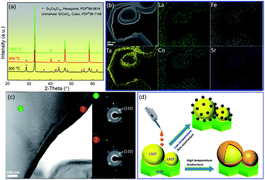
The phase and morphology of the SCT capping layer are critically important to the performance of the new infiltrated cathode. Fig. 1(a) shows that the onset temperature to form a pure perovskite SCT phase is 1000 °C. At this temperature, the morphology of the resultant bilayer cathode (collectively denoted as SCT@LSCF–GDC throughout this paper), shown in Fig. 1(b), exhibits a continuous SCT layer that is intimately bonded to the LSCF–GDC skeleton. This observation is uniquely different from conventional discrete nanoparticles (NPs) morphology widely reported in the literature. A continuous layer may have less specific reactive surface areas than discrete NPs, but it avoids coarsening of the NPs and thus is expected to be morphologically more stable.19 The first enabler for the conformal coating is the structural similarity between the two layers. The compositional analysis by STEM-EDX indicates that Ta from SCT is mostly concentrated in the outer layer, suggesting that it is likely the SCT capping layer. The diffraction patterns of Fig. 1(c) by TEM-SAED reveal that SCT and LSCF are virtually isostructural with identical (110) d-spacings (0.28 nm). This is not surprising given the fact that both SCT and LSCF are perovskites with corner-shared 3d metal–oxygen octahedra.18,20 However, having the same d-spacing seems to suggest that cation interdiffusions between SCT and LSCF may play a role in the chemical homogenization (except for Ta).
The second enabler for the continuous coating is the high calcination temperature. Early studies have indeed shown the dependence of the morphology of an infiltrated species upon the calcination temperature. For example, Lou et al. reported a discrete NPs morphology when calcining the isostructural Sm0.5Sr0.5O3−δ on a LSCF skeleton at 800 °C.21 Similar morphologies for SCT@LSCF are also observed in the present work at 800 °C when calcined for 2 h (see Fig. S1†). At higher calcination temperatures, such as ≥1000 °C, a transitional discrete-to-continuous layer of NPs was observed in non-isostructures (perovskite/fluorite) such as (Sm,Ce)-doped SrCoO3−δ@Sm0.2Ce0.8O1.9 at 1100 °C,22 and LaNi0.6FeO3−δ@YSZ (yttria-stabilized zirconia) at 1100 °C.23 However, no conformally coated structure such as the SCT@LSCF observed here, has been previously reported. To facilitate the understanding of this temperature–morphology relationship, we schematically illustrate in Fig. 1(d) the formation of discrete NPs and the continuous layer of SCT on LSCF at low and high temperature regimes, respectively.
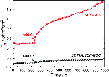
The ORR performance and Cr-tolerance of both the untreated (LSCF–GDC) and infiltrated (SCT@LSCF–GDC) cathodes are evaluated side-by-side in the same testing rig to avoid data variability. Fig. 2 shows the EIS-extracted polarization resistance (Rp) vs. time at 700 °C for the two cathodes. The original EIS spectra can be found in Fig. S2.† During the first 234 h of testing in clean air, the infiltrated cathode clearly outperforms the untreated one by demonstrating at least 4.5× lower Rp values. Single fuel cell testing with infiltrated cathode also shows better performance than the untreated cell (see Fig. S3†). As soon as the Cr-source (SS430) is introduced into the air stream, the untreated cathode responds with an appreciable jump in Rp, followed by a nearly monotonic increase with time. In contrast, response of the infiltrated cathodes to the Cr-addition is much less pronounced, with only a marginal increase. Compared with recent literature results tested in Cr-containing air, e.g. BaO infiltrated LSCF at 800 °C,13 La2NiO4+δ (LNO) infiltrated PrBa0.5Sr0.5Co1.5Fe0.5O5+δ (PBSCF) at 750 °C,24 GDC infiltrated LNF at 750 °C,25 LNF–GDC composite at 700 °C,26 LSCF at 750 °C,27 BSCF at 800 °C,28 in Fig. S4† we show that SCT@LSCF–GDC at 700 °C outperforms most of those materials, even though the former are at higher temperatures. BaCeO3 (ref. 29) and PrOx/PrNi0.5Mn0.5O3 (PNM)27 infiltrated LSCFs show smaller Rp values than SCT@LSCF–GDC, but they are also at higher temperatures (800 and 750 °C) and are only tested for much shorter times (40 and 72 h, respectively). We show later that the better Cr-resistance and ORR activity of the new infiltrated cathode demonstrated here are fundamentally derived from its SrO-free surface and thermodynamics.
 | ||
| Fig. 2 Time-dependent Rp of the untreated and infiltrated cathodes in clean and Cr-containing atmospheres. | ||
Similarly, the effects of CO2 and H2O on Rp values of both cathodes shown in Fig. S5† indicate that the change in Rp (ΔRp) induced by CO2 and H2O is far less for the infiltrated than for the untreated cathode in the temperature range of 550 to 700 °C, even though the overall impacts of these low concentrations of CO2 and H2O are marginal compared to the Cr-effect shown in Fig. 2. It is also interesting to notice that the CO2 and H2O effects are more pronounced at low temperatures than at high temperatures, implying the physical adsorption nature (not reaction) of the effect.
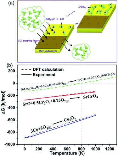
The results presented so far clearly demonstrate the infiltrated cathode's better Cr-tolerance and superior ORR activity compared to LSCF–GDC. To facilitate mechanistic understanding, we schematically show the surface reactions of the two cathodes in a Cr-containing environment in Fig. 3(a). It should be noted that the surface Sr-segregation in LSCF is well documented in literature30,31 and has also been confirmed in this study by our combined SEM and XPS analysis, showing a significantly higher level of surface Sr in LSCF than SCT (see Fig. S6†). In the presence of SrO on the surface of LSCF, the gaseous Cr-species such as CrO3(g) will readily react with SrO to form SrCrO4. The formed SrCrO4 is insulating and inactive, thus blocking ORR active sites. In contrast, SCT will not react with CrO3(g) because of its SrO-free surface. To further support the mechanistic findings, we carried out thermodynamic calculations of the Gibbs free energy change (ΔG) of the SCT-Cr reaction. Since the formation ΔG of SCT is unknown, we applied first-principle density functional theory (DFT) to calculate ΔG of the following reaction (details can be found in the ESI†):
| SrCo0.9Ta0.1O3 + 0.5Cr2O3 + 0.475O2(g) = SrCrO4 + 0.3Co3O4 + 0.05Ta2O5 | (1) |
Note that first-principle DFT calculations have been demonstrated in recent years as a useful tool to calculate thermodynamic quantities.32,33 The calculation results in Fig. 3(b) indicate that SCT will not react with CrO3(g) (in the form of Cr2O3 + O2) above 800 K, while SrO is highly reactive with CrO3(g). In Fig. 3(b), to ensure the accuracy and fidelity of the calculations, we also compare ΔG calculated from DFT with the experimental data of two well-known reactions; the shown excellent agreements demonstrate that the calculations for SCT-Cr reactions are reliable.
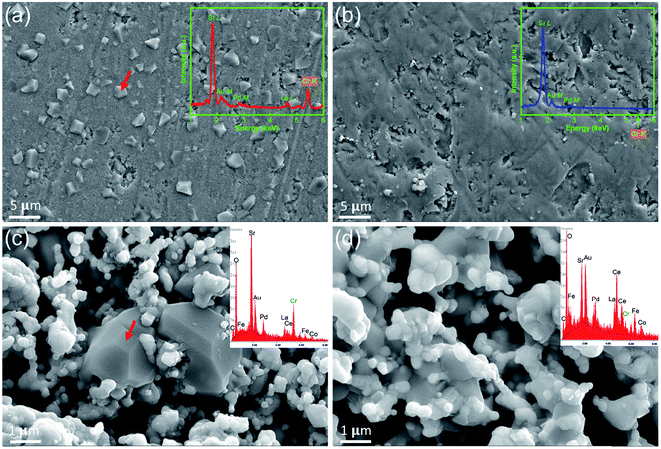
The hypothesis that the surface SrO is the active site to attract Cr-species is also verified experimentally by exposing dense LSCF and SCT pellets to a Cr-containing air at 900 °C for 100 h, followed by surface analysis of SEM/EDX. For the LSCF sample, many crystalline precipitates are clearly visible in Fig. 4(a). The EDX results suggest that these particles are Sr and Cr-containing compound, presumably SrCrO4, even though the semi-quantitative EDX suggests a Sr/Cr > 1 (some Sr may come from the LSCF base). Raman spectroscopic study (see Fig. S7†) of these particles indicates shifts at 854 cm−1, 880 cm−1 and 899 cm−1, matching well to the characteristic shifts of pure SrCrO4. In contrast, the SCT surface shown in Fig. 4(b) is clean and no Cr is detectable from the EDX. A more direct evidence of the Cr-resistance in the infiltrated cathode is given in Fig. 4(c) and (d), where the microstructures and local compositions of the two post-tested symmetrical cells (results in Fig. 2) are closely examined at the cathode/electrolyte interface. The untreated LSCF–GDC sample, shown in Fig. 4(c), contains distinctive and large-grained Sr- and Cr-rich phases. In contrast, Fig. 4(d) reveals the infiltrated cathode with no apparent SrCrO4 phase in the microstructure and a minimum amount of Cr detected by EDX.
In summary, a conformally coated cathode consisting of a SCT top nanoscaled layer and LSCF–GDC underlying skeleton has been demonstrated for the first time through combined solution infiltration and high temperature calcination. Owing to the excellent ORR activity and SrO-free surface in the top SCT layer, SCT@LSCF–GDC exhibits a much lower and more stable polarization resistance than its single layer LSCF–GDC counterpart. More importantly, the SrO-free surface in SCT shuts down the degradation mechanisms invoked by CrO3(g), H2O or CO2, thus making the new cathode more resilient and suited for SOFCs to operate under real-world conditions with low degradation rates.
Conflicts of interest
There are no conflicts to declare.Acknowledgements
This work was funded by National Energy Technology Laboratory, Office of Fossil Energy, U.S. Department of Energy, under award number DE-FE-0031671.References
- E. D. Wachsman and K. T. Lee, Science, 2011, 334, 935–939 CrossRef CAS PubMed.
- Z. Gao, L. V. Mogni, E. C. Miller, J. G. Railsback and S. A. Barnett, Energy Environ. Sci., 2016, 9, 1602–1644 RSC.
- C. Xia and M. Liu, Solid State Ionics, 2001, 144, 249–255 CrossRef CAS.
- Z. Shao and S. M. Haile, in Materials for Sustainable Energy: A Collection of Peer-Reviewed Research and Review Articles from Nature Publishing Group, World Scientific, 2011, pp. 255–258 Search PubMed.
- D. Oh, D. Gostovic and E. D. Wachsman, J. Mater. Res., 2012, 27, 1992–1999 CrossRef CAS.
- W. Jung and H. L. Tuller, Energy Environ. Sci., 2012, 5, 5370–5378 RSC.
- W. Lee, J. W. Han, Y. Chen, Z. Cai and B. Yildiz, J. Am. Chem. Soc., 2013, 135, 7909–7925 CrossRef CAS PubMed.
- N. Ni, C. C. Wang, S. P. Jiang and S. J. Skinner, J. Mater. Chem. A, 2019, 7, 9253–9262 RSC.
- S. J. Skinner, Adv. Mater. Interfaces, 2019, 1900580 CrossRef.
- Y. Zhen, A. Tok, S. P. Jiang and F. Boey, J. Power Sources, 2007, 170, 61–66 CrossRef CAS.
- Y. Zhen and S. P. Jiang, J. Power Sources, 2008, 180, 695–703 CrossRef CAS.
- X. Chen and S. P. Jiang, J. Mater. Chem. A, 2013, 1, 4871–4878 RSC.
- K. Chen, N. Ai, K. M. O'Donnell and S. P. Jiang, Phys. Chem. Chem. Phys., 2015, 17, 4870–4874 RSC.
- J. Hong, A. Aphale, S. J. Heo, B. Hu, M. Reisert, S. Belko and P. Singh, ACS Appl. Mater. Interfaces, 2019, 11, 34878–34888 CrossRef CAS PubMed.
- A. Aphale, M. A. Uddin, B. Hu, S. J. Heo, J. Hong and P. Singh, J. Electrochem. Soc., 2018, 165, F635–F640 CrossRef CAS.
- J. A. Schuler, A. J. Schuler, D. Penner, A. Hessler-Wyser and C. Ludwig, Electrochem. Solid-State Lett., 2011, 14, B132–B134 CrossRef.
- T. Yang, X. Jin and K. Huang, J. Membr. Sci., 2018, 568, 47–54 CrossRef CAS.
- J. Wang, T. Yang, L. Lei and K. Huang, J. Mater. Chem. A, 2017, 5, 8989–9002 RSC.
- Y. Gong, D. Palacio, X. Song, R. L. Patel, X. Liang, X. Zhao, J. B. Goodenough and K. Huang, Nano Lett., 2013, 13, 4340–4345 CrossRef CAS PubMed.
- G. Corbel, S. Mestiri and P. Lacorre, Solid State Sci., 2005, 7, 1216–1224 CrossRef CAS.
- X. Lou, S. Wang, Z. Liu, L. Yang and M. Liu, Solid State Ionics, 2009, 180, 1285–1289 CrossRef CAS.
- D. Chen, G. Yang, F. Ciucci, M. O. Tadé and Z. Shao, J. Mater. Chem. A, 2014, 2, 1284–1293 RSC.
- S. Lee, M. Bevilacqua, P. Fornasiero, J. Vohs and R. Gorte, J. Power Sources, 2009, 193, 747–753 CrossRef CAS.
- J. Li, J. Li, D. Yan, J. Pu, B. Chi and L. Jian, Electrochim. Acta, 2018, 270, 294–301 CrossRef CAS.
- B. Huang, X.-j. Zhu, R.-x. Ren, Y.-x. Hu, X.-y. Ding, Y.-b. Liu and Z.-y. Liu, J. Power Sources, 2012, 216, 89–98 CrossRef CAS.
- Y. Ling, H. Xie, Z. Liu, X. Du, H. Chen, X. Ou, L. Zhao and R. A. Budiman, Electron. Mater. Lett., 2018, 14, 432–439 CrossRef CAS.
- Y. Chen, S. Yoo, X. Li, D. Ding, K. Pei, D. Chen, Y. Ding, B. Zhao, R. Murphy and B. Deglee, Nano Energy, 2018, 47, 474–480 CrossRef CAS.
- Y.-M. Kim, X. Chen, S. P. Jiang and J. Bae, Electrochem. Solid-State Lett., 2011, 14, B41–B45 CrossRef CAS.
- K. Chen, M. Li, N. Ai and S. P. Jiang, Meeting Abstracts, The Electrochemical Society, 2016, pp. 2881–2881 Search PubMed.
- P. Van Der Heide, Surf. Interface Anal., 2002, 33, 414–425 CrossRef CAS.
- E. J. Crumlin, E. Mutoro, Z. Liu, M. E. Grass, M. D. Biegalski, Y.-L. Lee, D. Morgan, H. M. Christen, H. Bluhm and Y. Shao-Horn, Energy Environ. Sci., 2012, 5, 6081–6088 RSC.
- F. Calle-Vallejo, J. I. Martínez, J. M. García-Lastra, M. Mogensen and J. Rossmeisl, Angew. Chem., Int. Ed., 2010, 49, 7699–7701 CrossRef CAS PubMed.
- L. Wang, T. Maxisch and G. Ceder, Phys. Rev. B: Condens. Matter Mater. Phys., 2006, 73, 195107 CrossRef.
Footnotes |
| † Electronic supplementary information (ESI) available: Experimental and computational methods; SEM image of SCT@LSCF at 800 °C; impedance spectra with the presence of Cr; single cell performance; Rp in Cr-containing atmosphere; impedance spectra under CO2 and H2O containing air; the cathodes morphology and Sr-3d XPS spectra in symmetrical cells post- and pre-annealing at 700 °C; Raman spectra of LSCF pellet after annealing in Cr-containing air. See DOI: 10.1039/c9ta11657e |
| ‡ These authors contributed equally. |
| This journal is © The Royal Society of Chemistry 2020 |


