 Open Access Article
Unparalleled mitigation of membrane degradation in fuel cells via a counter-intuitive approach: suppression of H2O2 production at the hydrogen anode using a Ptskin–PtCo catalyst†
Guoyu
Shi
 a,
Donald A.
Tryk
 b,
Toshio
Iwataki
b,
Hiroshi
Yano
b,
Makoto
Uchida
b,
Toshio
Iwataki
b,
Hiroshi
Yano
b,
Makoto
Uchida
 b,
Akihiro
Iiyama
b and
Hiroyuki
Uchida
 *ab
*ab
aClean Energy Research Center, University of Yamanashi, Takeda 4, Kofu, 400-8510, Japan. E-mail: h-uchida@yamanashi.ac.jp
bFuel Cell Nanomaterials Center, University of Yamanashi, Takeda 4, Kofu, 400-8510, Japan
First published on 9th January 2020
Abstract
Hydroxyl radicals (˙OH) are responsible for much of the degradation of the proton exchange membrane (PEM) used in fuel cells. The conventional approach has been to use radical scavengers incorporated into the PEM, but performance is decreased. Here, we propose a counter-intuitive strategy in which the production of hydrogen peroxide, the precursor of ˙OH, is suppressed at the hydrogen anode, where oxygen diffusing from the cathode is reduced by adsorbed hydrogen atoms. This is accomplished via the use of a Pt skin-covered PtCo alloy anode catalyst, on which H is weakly adsorbed, as indicated by theoretical calculations. In particular, the H2O2 production on the hydrogen anode at a practical temperature of 80 °C was, for the first time, evaluated by the application of the channel flow double electrode (CFDE) technique. A remarkably longer lifetime of a PEM with the PtCo/C anode, in comparison with that for a commercial Pt/C anode, has been demonstrated in an accelerated stress test of a single cell (open circuit under pressurized gases).
The widespread use of zero-emission fuel cell vehicles (FCVs) could be highly beneficial for improving urban air quality and energy efficiency. However, to facilitate the conversion to FCVs, it will be necessary to drastically lower costs, for example, by greatly increasing the durability of the costly proton exchange membrane (PEM) in the polymer electrolyte fuel cell (PEFC).1–5 The durability problem is particularly acute when thin, low-resistance membranes are used to boost performance. Chemical degradation of the PEMs, for example, those based on perfluorosulfonic acid (PFSA) such as Nafion, by OH radical (˙OH) attack is one of the most serious issues for fuel cell durability. These radicals are produced via the decomposition of hydrogen peroxide, H2O2, which is produced when O2 gas diffuses through the PEM and is reduced by adsorbed hydrogen atoms on the Pt/C catalyst. The ˙OH radicals are generated by the reaction of H2O2, primarily with metal ion impurities such as Fe2+ present in the PEM (H2O2 + Fe2+ → ˙OH + OH− + Fe3+) and secondarily with the acidic PEM.6 An obvious direct strategy is to scavenge the ˙OH radicals, which has been done with the use of Ce3+ ions incorporated in the PEMs: ˙OH + Ce3+ + H+ → Ce4+ + H2O. The oxidized form Ce4+ ions can be reduced back to Ce3+ by H2 present in the PEMs: Ce4+ + 1/2 H2 → Ce3+ + H+.7 However, the ion exchange of Ce ions in the PEM results in decreased proton conductivity.8 Furthermore, Ce ions migrate through the PEM from the anode to the cathode, resulting in a loss of cathode performance due to decreased ionomer conductivity.9
Moreover, our theoretical work has shown that H2O2 itself decomposes hydrated PFSA through the dissociation of the ether linkages of the side chain, which cannot be mitigated by radical scavengers.10 Therefore, even though counter-intuitive, a more fundamental approach is to suppress H2O2 production at the hydrogen anode. Here, we propose a new approach, in which we decrease the H2O2 production rate itself by the use of a stabilized Pt skin–PtCo anode nanocatalyst supported on carbon (PtxAL–PtCo/C).11–13 We compare the results of both half-cell and full-cell measurements with those for a commercial Pt/C (c-Pt/C) catalyst.
In order to focus on this new approach, we have needed to develop a new technique to measure H2O2 production occurring simultaneously with the hydrogen oxidation reaction (HOR). While the quantitative measurement of H2O2 produced via the oxygen reduction reaction (ORR) at cathode catalysts has been well established, including the use of the rotating ring-disk electrode (RRDE) and channel flow double electrode (CFDE) techniques,14–18 there has been no report of evaluating H2O2 production occurring during the HOR, particularly at the anode under practical conditions. Compared with the RRDE, one of the advantages of the CFDE technique is the precise control of H2 or O2 concentration in the electrolyte solution at practical temperatures for a PEFC from 30 to 90 °C.19 In this work, we have developed a new method based on the CFDE technique and have demonstrated the potential dependence of H2O2 production at the anode contacted with a mixture of H2 and air (10%), simulating the diffusion (crossover) of O2 from the cathode to the hydrogen anode.
The catalyst PtxAL–PtCo/C (30 mass%-Pt loading) tested was a PtCo alloy prepared in-house with a stabilized Pt-skin supported on carbon black (specific surface area 780 m2 g−1).11–13 As we reported previously,11 based on the analyses of TEM, XRD, high resolution STEM and EDX line scans, we have determined the thickness of the Pt skin (PtxAL) as being 1–2 atomic layers for the as-prepared catalyst. A commercial Pt/C catalyst (30 mass%-Pt loading, TEC10F30E) from Tanaka Kikinzoku Kogyo (TKK) was used for comparison. TEM images of all catalysts used are shown in Fig. S1 in the ESI.† The electrochemical experiments were conducted with a CFDE cell in 0.1 M HClO4 at 80 °C. The working electrode (WE) employed herein was a glassy carbon (GC) substrate in order to minimize the H2O2 production. A Pt wire was used as the counter electrode. The reference electrode used was a reversible hydrogen electrode (RHE), and all of the electrode potentials in this paper are given versus the RHE. The collection electrode was set at 1.4 V vs. RHE in order to detect H2O2 while minimizing the HOR current.20 Details on the measurement are given in the ESI.†
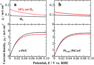
Fig. 1a shows the hydrodynamic voltammograms for the HOR on c-Pt/C in 0.1 M HClO4 saturated with pure H2 and 10% air/H2-balance at 80 °C. In H2-saturated solution, the HOR current density at the c-Pt/C working electrode (WE) commenced at 0.00 V vs. RHE and reached diffusion limits at ca. 0.06 V. The oxidation current density at the Pt collecting electrode CE (jC) located downstream of the WE was relatively small and nearly constant, irrespective of the WE potential, which is ascribed to the HOR on the less active PtOx-covered electrode at the high potential of 1.4 V. In contrast, in 10% air/H2-saturated solution, the HOR current density at the WE decreased slightly due to an overlap of the ORR, and H2O2 emitted from the WE was detected as an oxidation current at the CE. The jC increased gradually with decreasing potential. We also performed a similar experiment by the use of PtxAL–PtCo/C, as shown in Fig. 1b. The H2O2 production current density, j(H2O2), was calculated as a function of potential, as follows:
| j(H2O2) = [jC(10% air/H2) − jC(H2)]/N | (1) |
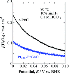
As shown in Fig. 2, j(H2O2) on both catalysts increased at less positive potentials, and reached the highest value at 0 V, which is consistent with the accelerated degradation of PEMs at open circuit in a single cell.21–23 It is clear that the values of j(H2O2) on the PtxAL–PtCo/C catalyst were less than 1/2 of those on c-Pt/C at 0 ≤ E ≤ 0.06 V (practical anode potentials for the HOR). The PtxAL–PtCo/C is also intrinsically more active for the HOR than pure Pt (see Fig. S4†),13i.e., high HOR activity together with low H2O2 production rate.
 | ||
| Fig. 2 Potential-dependent H2O2 oxidation current density, j(H2O2), for PtxAL–PtCo/C and c-Pt/C measured in 10% air/H2-saturated 0.1 M HClO4 at 80 °C. | ||
We have also measured j(H2O2) during the cathodic ORR in O2-saturated solution (Fig. S5†). Consistent with the 10% air/H2 condition, the H2O2 production was also shown to be remarkably suppressed on PtxAL–PtCo/C in comparison with that on c-Pt/C. Surprisingly, the j(H2O2) values obtained from the HOR (10% air/H2) and ORR (pure O2) experiments were nearly the same for both catalysts (see Fig. S6†). This result suggests that the rate-determining step (rds) for H2O2 production should include a potential-dependent limiting species other than the O2 molecule, as discussed below.
It is necessary to note that possible trace impurities in the electrolyte solution, such as organic adsorbates or halide anions, could increase the H2O2 production rate on Pt-based catalysts due to strong adsorption.16 However, in all of our work, the electrolyte solution used has been carefully purified with conventional pre-electrolysis methods.16 The adsorption of the ClO4− anion on Pt is relatively weak, and its influence on the reaction pathway on the ORR, as well as the HOR, is negligible in the potential region less positive than the potential of zero charge (pzc, ca. 0.3 to 0.4 V vs. RHE).17 Thus, the current density, i.e., j(H2O2) can provide a valid comparison of the H2O2 production rates of different catalysts.
Density functional theory (DFT) calculations were conducted to understand the electrocatalysis for the H2O2 production at Pt or Pt skin-covered PtCo anode. Based on the monotonic increase of j(H2O2) with decreasing potential (Fig. 2) together with our previous in situ FTIR study,24 the production of H2O2 can be correlated with the onset of overpotentially-deposited hydrogen (HOPD) formation on the Pt surface at potentials below 0.1 V vs. RHE. We propose that O2 is reduced to H2O2 by HOPD on (111) facets, similar to the case for Pt(111) single crystals (see Fig. S7 and S8†).
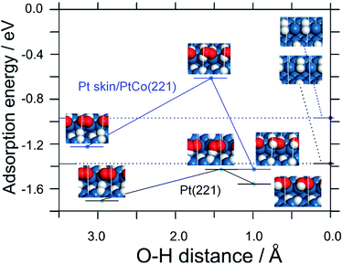
In order to systematically elucidate the present experimental results, we constructed stepped (221) surfaces in which O2 adsorbs in the bridging configuration at (110) step edges, and HOPD on a lower (111) terrace reacts initially to form HO2 (Fig. 3 and S9†). From Table S2,† the adsorption of both HOPD and HUPD on Pt skin/PtCo(221) is shown to be weaker than that on Pt(221), leading to less blocking of sites for O2 adsorption in the bridging configuration, which is responsible for the lower H2O2 production rate. The expected lower coverage of HOPD would also help to suppress H2O2 production. The weakened H adsorption or lowered coverage might be ascribed to the modified electronic properties of the Pt skin surface due to the presence of Co below the surface, e.g., narrowing of the d-band,25 due to the exchange of electrons between the Co and Pt d-bands.
Furthermore, from Fig. 3 and Table S2,† the activation energy for the reaction of producing adsorbed HO2 intermediate (O2,ad + HOPD,ad → HO2,ad) is shown to be larger on Pt skin/PtCo(221) compared with that on Pt(221) (0.6 eV vs. 0.3 eV). This is consistent with the lower H2O2 production rate on PtxAL–PtCo than that on Pt. Thus, the DFT calculations can explain the main features of the experimental results, i.e., the independence upon O2 concentration and the potential dependence that is consistent with the onset of HOPD formation.
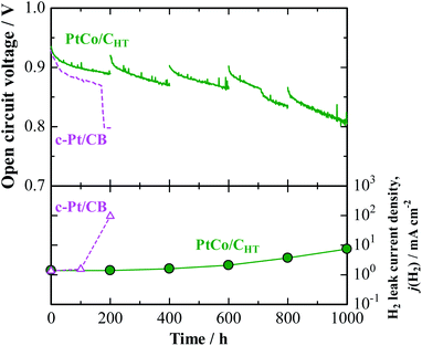
A noticeably prolonged lifetime of a PEM by the use of the anode catalyst with decreased H2O2 production rate has been demonstrated by a single cell test. Its performance was compared with that of a cell with a commercial Pt/CB anode (Pt-loaded carbon black, 50 mass%-Pt loading, TEC10E50E). The cathode catalyst was a commercial Pt/GCB (Pt-loaded graphitized carbon black, 50 mass%-Pt loading, TEC10EA50E-HT). For the preparation of a catalyst-coated membrane (CCM, based on Nafion, 25 μm thickness, geometric electrode area = 29.2 cm2), a proprietary catalyst, designated PtCo/CHT (15 mass%-Pt loading), which was designed to be nearly identical with the in-house-prepared catalyst, has been prepared at the 10 gram scale as part of a collaboration with TKK (Tanaka Kikinzoku Kogyo). We have found that for PtCo/CHT, after potential cycling in 0.1 M HClO4 at 80 °C, a Pt skin with 1–2 atomic layers was formed on the Pt–Co alloy surface (see Fig. S2† for EDX line scan analysis), so that the electrochemical behavior was very similar to that of PtxAL–PtCo/C. Indeed, we observed by the CFDE technique that this catalyst exhibited a similar reduction of j(H2O2) measured in both 10% air/H2- and O2-saturated solutions (see Fig. S3 and S6†), together with high area-specific activity for the HOR (Fig. S4†). An accelerated stress test (AST) of the PEM under open-circuit conditions in an H2/air single cell was performed at 90 °C and 160 kPaG (see ESI† for details).26 Due to the use of a large amount of Pt at the anode and cathode (0.5 mgPt cm−2) for the AST, both cells exhibited nearly the same initial I–V performances (Fig. S10†). However, as shown for the cell with a conventional c-Pt/CB anode in Fig. 4, the cell voltage dropped significantly after only 160 h, at which an abrupt increase in the H2 leak current density j(H2), by approximately two orders of magnitude, was observed. In post-test analysis, a pinhole was found to have been formed in a region near the center of the CCM, probably due to the chemical degradation of the membrane.26 In contrast, the cell with the PtCo/CHT anode exhibited high durability, without any significant decrease in OCV, so that the j(H2) increased by a factor of only 1.5 after 600 h. Judging from the increase in j(H2), as well as changes in the cyclic voltammograms at the cathode shown in Fig. S11,† H2 leakage through the PEM increased steeply between 600 and 800 h, but the degradation was much milder than that for the c-Pt/CB cell, which suffered a catastrophic loss of gas-tightness. It is noted in Table S3† that the Co content of PtCo/CHT in the anode catalyst layer after the OCV test at 90 °C for 1000 h remained at a fairly high level, 26 ± 8 atom%, with a small standard deviation, which decreased from 35 ± 11 atom% for an untested reference sample. Such a suppression of the dealloying of Co in the PtCo/CHT anode catalyst can be ascribed with certainty to the formation of a Pt skin layer and can contribute greatly to maintaining the decreased H2O2 production rate, resulting in enhanced chemical durability of the PEM.
 | ||
| Fig. 4 Time course of open-circuit voltage (OCV) and H2 leak current density for single cell with PtCo/CHT or c-Pt/CB anode operated with H2–air humidified at 76% RH and 86% RH at 90 °C and 160 kPaG. The data for the cell with c-Pt/CB were cited from ref. 26. | ||
Conclusions
The present results have shown that the peroxide production rate can be decreased by as much as 50% if Pt–Co alloy catalysts are used at the hydrogen anode in PEFCs. DFT calculations indicate that the suppression of H2O2 production can be ascribed to the lowered binding energy of HOPD on the Pt-skin surface. A fuel cell utilizing PtCo/CHT as the anode catalyst has exhibited excellent durability under accelerated OCV conditions due to the mitigation of chemical degradation of the membrane. This seemingly counter-intuitive approach of suppressing radical attack via the suppression of peroxide production at the hydrogen anode is expected to contribute greatly to the development of next-generation PEFCs.Conflicts of interest
There are no conflicts to declare.Acknowledgements
This work was supported by funds for the ‘‘Superlative, Stable, and Scalable Performance Fuel Cells” (SPer-FC) project from the New Energy and Industrial Technology Development Organization (NEDO) of Japan. The authors are grateful to Honda R&D Co., Ltd. for kindly providing the accelerated stress test protocol with pressurized OCV conditions, and to Tanaka Kikinzoku Kogyo for providing the PtCo/CHT catalyst.Notes and references
- F. N. Büchi, M. Inaba and T. J. Schmidt, Polymer Electrolyte Fuel Cell Durability, Springer, Berlin, 2009 Search PubMed.
- J. Peron, Z. Shi and S. Holdcroft, Energy Environ. Sci., 2011, 4, 1575–1591 RSC.
- M. Zatoń, J. Rozière and D. J. Jones, J. Mater. Chem. A, 2017, 5, 5390–5401 RSC.
- J. Miyake, R. Taki, T. Mochizuki, R. Shimizu, R. Akiyama, M. Uchida and K. Miyatake, Sci. Adv., 2017, 3, eaao0476 CrossRef.
- T. Holmes, T. J. G. Skalski, M. Adamski and S. Holdcroft, Chem. Mater., 2019, 31, 1441–1449 CrossRef CAS.
- M. Aoki, H. Uchida and M. Watanabe, Electrochem. Commun., 2006, 8, 1509–1513 CrossRef CAS.
- E. Endoh, ECS Trans., 2008, 16(2), 1229–1240 CAS.
- A. M. Baker, S. K. Babu, R. Mukundan, S. G. Advani, A. K. Prasad, D. Spernjak and R. L. Borup, J. Electrochem. Soc., 2017, 164, F1272–F1278 CrossRef CAS.
- K. H. Wong and E. Kjeang, J. Electrochem. Soc., 2019, 166, F128–F136 CrossRef CAS.
- T. Tsuneda, R. K. Singh, A. Iiyama and K. Miyatake, ACS Omega, 2017, 2, 4053–4064 CrossRef CAS PubMed.
- M. Watanabe, H. Yano, D. A. Tryk and H. Uchida, J. Electrochem. Soc., 2016, 163, F455–F463 CrossRef CAS.
- M. Chiwata, H. Yano, S. Ogawa, M. Watanabe, A. Iiyama and H. Uchida, Electrochemistry, 2016, 84, 133–137 CrossRef CAS.
- G. Shi, H. Yano, D. A. Tryk, A. Iiyama and H. Uchida, ACS Catal., 2016, 7, 267–274 CrossRef.
- N. Markovic, H. Gasteiger and P. N. Ross, J. Electrochem. Soc., 1997, 144, 1591–1597 CrossRef CAS.
- M. Inaba, H. Yamada, J. Tokunaga and A. Tasaka, Electrochem. Solid-State Lett., 2004, 7, A474–A476 CrossRef CAS.
- H. Yano, E. Higuchi, H. Uchida and M. Watanabe, J. Phys. Chem. B, 2006, 110, 16544–16549 CrossRef CAS PubMed.
- V. A. Sethuraman, J. W. Weidner, A. T. Haug, S. Motupally and L. V. Protsailo, J. Electrochem. Soc., 2008, 155, B50–B57 CrossRef CAS.
- H. Nishikawa, H. Yano, J. Inukai, D. A. Tryk, A. Iiyama and H. Uchida, Langmuir, 2018, 34, 13558–13564 CrossRef CAS PubMed.
- H. Uchida, K. Izumi, K. Aoki and M. Watanabe, Phys. Chem. Chem. Phys., 2009, 11, 1771–1779 RSC.
- G. Shi, H. Yano, D. A. Tryk, S. Nohara and H. Uchida, Phys. Chem. Chem. Phys., 2019, 21, 2861–2865 RSC.
- E. Endoh, S. Terazono, H. Widjaja and Y. Takimoto, Electrochem. Solid-State Lett., 2004, 7, A209–A211 CrossRef CAS.
- M. Inaba, T. Kinumoto, M. Kiriake, R. Umebayashi, A. Tasaka and Z. Ogumi, Electrochim. Acta, 2006, 51, 5746–5753 CrossRef CAS.
- A. Ohma, S. Suga, S. Yamamoto and K. Shinohara, J. Electrochem. Soc., 2007, 154, B757–B760 CrossRef CAS.
- K. Kunimatsu, H. Uchida, M. Osawa and M. Watanabe, J. Electroanal. Chem., 2006, 587, 299–307 CrossRef CAS.
- G. Shi, H. Yano, D. A. Tryk, M. Matsumoto, H. Tanida, M. Arao, H. Imai, J. Inukai, A. Iiyama and H. Uchida, Catal. Sci. Technol., 2017, 7, 6124–6131 RSC.
- R. Shimizu, J. Tsuji, N. Sato, J. Takano, S. Itami, M. Kusakabe, K. Miyatake, A. Iiyama and M. Uchida, J. Power Sources, 2017, 367, 63–71 CrossRef CAS.
Footnote |
| † Electronic supplementary information (ESI) available: Experimental details and supplementary figures. See DOI: 10.1039/c9ta12023h |
| This journal is © The Royal Society of Chemistry 2020 |


