Spectator cation size effect on the work function and stability of self-compensated hole-doped polymers†
Mervin Chun-Yi
Ang
a,
Qi-Mian
Koh
a,
Cindy Guanyu
Tang
b,
Qiu-Jing
Seah
a,
Yu
Wang
a,
Martin
Callsen
b,
Yuan-Ping
Feng
b,
Rui-Qi
Png
 b and
Lay-Lay
Chua
 *ab
*ab
aDepartment of Chemistry, National University of Singapore, Lower Kent Ridge Road, S117552, Singapore. E-mail: chmcll@nus.edu.sg
bDepartment of Physics, National University of Singapore, Lower Kent Ridge Road, S117550, Singapore
First published on 15th November 2019
Abstract
The ‘free’ ions needed to balance the ‘fixed’, covalently bonded ions in a conventional polyelectrolyte are often thought to play little role beyond charge balancing, processability and morphology control. In self-compensated, hole-doped polymers, free cations, together with mobile holes on the polymer backbone, balance the covalently tethered counter-anions. We show here that these ‘spectator’ cations not only influence the ionization energy (and work function) of the polymer, but also, perhaps surprisingly, determine the stability of the ultrahigh-workfunction state. We attribute these two effects to the dependence on the spectator cation size of surface ionic layering, and coulombic stabilization of the anion sites, respectively. The smaller cations provide larger coulombic stabilization of the anionic site, raising the energetic barrier for hole transfer to the anion or its hydration water, thereby blocking de-doping of the polymer backbone. We demonstrate these effects in an important model of a high-ionization-energy triarylamine–fluorene copolymer TFB with trifluoromethanesulfonylimidosulfonyl as a tethered counter-anion, and a family of spherical monovalent cations as spectators (Li+, Na+, Cs+, NMe4+ and NEt4+). Using Li+ as a spectator cation, we further demonstrate ultrahigh-workfunction hole injection layers for TFB semiconductor with markedly enhanced stability to ambient processing and baking. This work leads to a new design rule for stable, self-compensated, hole-doped polymer systems with ultrahigh work function.
Introduction
Charge injection and collection layers are needed to achieve ohmic injection and extraction, respectively, of carriers for high performance organic semiconductor devices. Thin conjugated polyelectrolytes (CPEs) can assist carrier injection by blocking opposite carriers from the other contact to produce a strong electric field.1–4 The confinement of opposite carriers to improve injection has been established some time ago from layer-by-layer assembled polyelectrolyte interlayers.5,6 In addition, this mechanism could be further assisted by the formation of interfacial dipoles at the metal/CPE interface which assist charge injection into the CPE interlayer.1,7–9 It was hypothesized that the free ions in these CPEs, whether cations9 or anions,1,7,8 can influence the dipole at the metal/CPE contact and hence its injection properties. Under some circumstances, in particular polyanionic CPEs with low ionization energy (IE) can become hole doped by acid added during dialysis.10 The spectator cation influences the extent of doping, with smaller ones (such as Na+) exhibiting a higher doping level than the larger ones (K+ and NMe4+).11,12 Alternatively, CPEs can also be exploited as self-assembled monolayers on electrode surfaces to induce interfacial δ-doping of the adjacent semiconductor layer, charge-balanced by the polyelectrolyte counter-ion monolayer.13Most recently, self-compensated (SC), charge-doped polymers made by separate doping with powerful redox agents and self-compensation through excess salt removal have been developed.14 These provide access to an ultrawide range of work functions (WFs) from 3.0 eV to 5.8 eV, enabling ohmic electron and hole injection into practically all organic semiconductors, with built-in resilience against ‘dopant’ migration. The use of these doped interlayers with more complex ionic–electronic properties opens up new questions on the effects of the tethered ion and the spectator ion. The effects of the tethered anion on the ionization energy and WF of model polymers have been studied recently.15 A wide variety of spectator ions can be incorporated to control properties, such as solubility, morphology, and device properties, particularly for tethered sulfonate9 and tethered trimethylammonium1,7,8 conjugated polyelectrolytes.
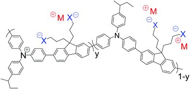
Here, we show that the spectator cations in SC, heavily hole-doped polymers play additional roles in determining the work function and stability of the hole-doped state. We designed and synthesized poly(9,9-bis(3-(trifluoromethanesulfonylimidosulfonyl)propyl)fluorene-2,7-diyl-alt-1,4-phenylene-(m-trifluoromethylphenylimino)-1,4-phenylene), denoted as TFB-CF3SIS-M (for the chemical structure, see Fig. 1), where M is a monovalent spectator cation. The semiconductor core is the well-known triarylamine–fluorene (TAF) copolymer TFB. TAF semiconductors provide chemical ‘tuneability’ of the WF in the ultrahigh range through pendant ring substitution without perturbing the rest of the polymer backbone.16 The trifluoromethanesulfonylimidosulfonyl (CF3SIS) anion tethered to propyl side chains is selected because it confers a higher WF,15 better processability17 and greater stability18 to the hole-doped state, than the sulfonate anion, owing to its larger size and lower hygroscopicity. We studied TFB-CF3SIS-M in both its undoped and hole-doped states. We selected the TFB core for study here because it gives the least stable hole-doped state in the TAF family, presumably due to the greater rotational mobility of the pendant ring. It also has the lowest glass transition temperature (140 °C). Understanding the stability trends in this material will therefore provide insight into designing other even more stable systems. We introduced different spectator cations by resin ion-exchange and characterized the resultant materials by ultraviolet photoemission spectroscopy, variable-angle X-ray photoemission spectroscopy, molecular dynamics simulation, quantum chemical calculations, and device studies.
General
Resin ion-exchange provided a reliable and convenient means to introduce different spectator ions into the system. This methodology eliminates possible variations in molecular weight and other synthesis issues. Amberlyst® 15 (H form) was first converted by aqueous M(OH) to the M form, which was then washed and conditioned in acetonitrile. The starting polyelectrolyte TFB-CF3SIS-Na was exchanged with TFB-CF3SIS-M, where M = (Li, Cs, NMe4, NEt4), in acetonitrile, using the respective M resins. Completion of ion-exchange was verified by 1H NMR (for NMe4+ and NEt4+), ICP-OES elemental analysis (for Li+), and X-ray photoemission spectroscopy (the rest of the ions).We generally found that the CF3SIS tethered anion induces better solubility of both the undoped and doped states of the TAF polymers in polar organic solvents. The undoped state is soluble (>20 mg mL−1) in acetonitrile, nitromethane, dimethylsulfoxide, N,N-dimethylformamide, methanol, tetrahydrofuran, and propylene carbonate, with larger cations inducing slightly better solubility. The TFB-CF3SIS-M polymers were solution hole-doped using a strong oxidant nitrosonium hexafluoroantimonate in anhydrous acetonitrile and purified by repeated precipitation to generate a SC heavily hole-doped TFB-CF3SIS-M family for study. These are soluble in the following solvents which have sufficiently high anodic potential limits: acetonitrile, nitromethane and propylene carbonate. Films were then deposited from acetonitrile solutions. There is an increasing loss of M+ as its size gets larger, presumably due to the selectivity of the tethered CF3SIS anion for smaller cations.
Trend in work function of hole-doped films
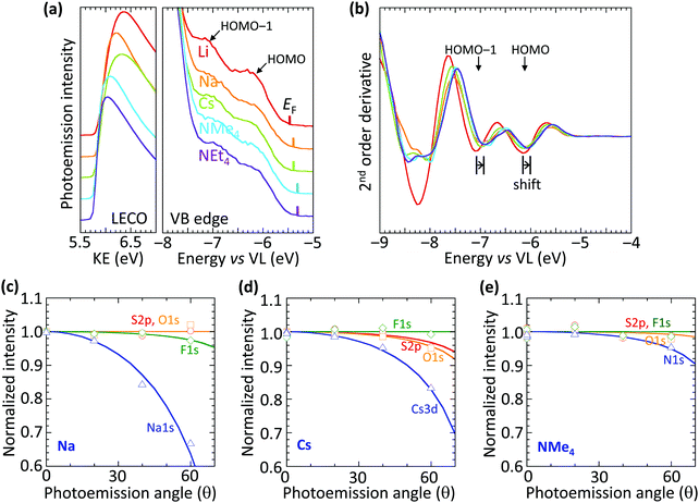
The vacuum WF of the heavily hole-doped TFB-CF3SIS-M films decreases marginally, but systematically, with spectator cation sizes across the family of M, from 5.45 eV for Li, to 5.3 eV for NMe4 and NEt4, as shown in Table 1. This is established by ultraviolet photoemission spectroscopy using a usual method: WF = hν − (KEFL − KELECO), where hν is the photon energy (He I, 21.21 eV), KEFL is the kinetic energy of photoelectrons emitted from the Fermi level and KELECO is that at the low-energy cut-off. The spectra are shown in Fig. 2a for the low-energy cutoff and valence band regions. The second derivative spectra for the valence band region are shown in Fig. 2b. They reveal the HOMO and HOMO−1 molecular orbital features, which arise from the fluorene and triarylaminium moieties respectively,16 and are useful markers because of their (nearly) no-dispersive character, downshift rigidly by 0.15 eV as M changes from Li to NEt4. This indicates that the reduction in the WF can be solely accounted for by a corresponding change in the surface dipole voltage of the films with spectator cation size. In contrast, changing the spectator cation M in hole-doped poly(3,4-ethylenedioxythiophene):poly(styrenesulfonate) (PEDT:PSSM) films does not alter the surface dipole voltage,19 although the introduction of a perfluorinated ionomer PFI in PEDT:PSSH:PFI does.20 Also, changing the tethered counter-anion in SC, holed-doped polymers does alter this dipole voltage.15| Cation | Ionic radiusa (Å) | Work functionb (eV) |
|---|---|---|
| a Apparent radius of the cation when coordinated by oxygen atoms from S–O of the sulfonylimidosulfonyl groups, evaluated from the molecular dynamics g(r) function from a self-consistent van der Waals radius of oxygen of 1.25 Å. These ionic radii are smaller than the standard tabulated Shannon crystal radii for size-coordinated ions for Li+ to K+, but larger than those for NMe4+ and NEt4+, as a consequence of the increase in the coordination number down the series. b Vacuum work function, measured by ultraviolet photoemission spectroscopy. | ||
| Li+ | 0.64 | 5.45 |
| Na+ | 1.01 | 5.4 |
| K+ | 1.42 | |
| Cs+ | 1.71 | 5.4 |
| NMe4+ | 2.47 | 5.3 |
| NEt4+ | 2.84 | 5.3 |
The trend in dipole voltage arises from surface ionic layering, similar to the situation when the tethered counter-anion is changed.15 This is confirmed by the angle dependence of the normalized core-level emissions measured by variable-angle XPS, as shown in Fig. 2c–e, for Na, Cs and NMe4, respectively. The core-level spectra are shown in ESI† Fig. S3. The angle dependence is characterized by an apparent depletion depth (zo) which reveals that the tethered anion is distributed all the way to the surface (zo, 0–1 Å), but the spectator cations are depleted from the surface, more for the smaller cations: Na+, 3.6 Å > Cs+, 3.0 Å > NMe4+, 1.2 Å. This produces an ionic double layer at the surfaces of these films, with the extent of charge layering, as judged by the difference Δzo, increasing with the decreasing spectator cation size. This is qualitatively similar to the vertical segregation observed at the water/air interface of alkali halide solutions,21,22 which suggests that the CPE surfaces are driven by similar considerations, despite frustration of the mobility of the anion by the tether. Although the films are undoped, for simplicity, the ionic layering is known to be robust, persisting in the doped films.15 This atomic scale layering produces a surface dipole voltage which is negative at the surface and positive in the bulk, favorably increasing the WF for hole injection, but without adding a significant charge-tunneling barrier across the interface.
Trend in the bulk ion-cluster morphology by MD simulations
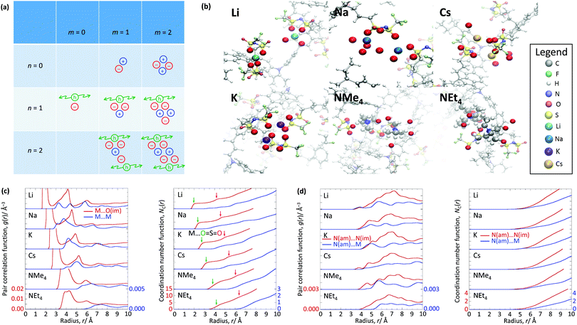
The WF is also determined by the chemical potential of the carriers.23,24 This is set by the electronic band structure in the limit of perfect screening, modified by the local Madelung potential set up by the counter ion, and other ions and carriers, in the vicinity of the first carrier site.16,19 The effect of such a Coulomb potential disordering has previously been analysed for carrier mobility in a point-carrier approximation.25 Therefore, we performed MD simulations on fully hole-doped (i.e., 1 h+ r.u.−1) samples to evaluate whether there is a difference in the local Madelung potential with spectator cation size. TFB-CF3SIS-M, where M = Li, Na, K, Cs, NMe4 and NEt4, was investigated using the AMBER package26 and the generalised AMBER force field.27 The atomic charges were calibrated by the RESP method using HF/6-31g(d) calculations.28 The final densities were calibrated to experimental ones (see Experimental). The ion-specific binding configurations were determined using DFT/CAM-B3LYP/6-31++G(d,p) in the case of Li and Na, where such effects may be expected. A subset of the most important theoretical charge-neutral local ion clusters is denoted by (n, m) where n is the number of hole–anion pairs, and m is the number of spectator cation–anion pairs, in the same cluster, as shown in Fig. 3a. The ions and holes belong to the same cluster when they are in ionic contact with at least one other hole or ion in that cluster. Of these, we expect the ‘average’ structure to be either (1, 1) or (2, 2), based on stoichiometry for a fully hole-doped material, which evolves towards (0, m) for undoped materials, where m is limited by the degree of aggregation of the tethered anions. The MD calculations reveal that indeed the ion clusters are small and, generally of the (2, 2) type, for all spectator cations, as shown in Fig. 3b.As expected, M is coordinated to the imide oxygen atoms, O(im), which bear a substantial part of the negative charge density. Both the atom pair correlation function g(r), and the coordination number function NC(r) defined by:  , show that the distance r to the first coordination shell for M⋯O(im) increases as the cation size increases, as shown in Fig. 3c, and so, g(r) and NC(r) for M⋯M also increase. However, g(r) and NC(r) for N(am)⋯N(im), which is the proxy for hole to tethered counter-anion remain practically unchanged with the spectator cation, NC(r) reaching unity at 6.2–6.4 Å, which is not surprising because the counter-anion is in ionic ‘contact’ with the hole. Furthermore, g(r) and NC(r) for N(am)⋯M exhibit a similar ‘averaged’ distance which is independent of M, while showing fine structures due to the bonding configuration differences, where the smaller spectator cations can penetrate to the leading edge of the tethered anion distribution. NC(r) reaches unity identically at 7.5 Å for all cations.
As a consequence, the local Madelung potential set up by the ion cluster turns out to be practically independent of spectator cation size, in contrast to the strong counter-anion size effect15 and the strong spectator-size effect found in PEDT:PSSM, where the anion head group is smaller.19 In a first-order point-charge approximation, the Madelung potential at the hole site is evaluated using the following equation:  , where h–an is the hole-to-anion distance, h–cat is the hole-to-cation distance and h–h is the hole-to-hole distance, and RS is the screening radius. We estimate VM ≈ −1.20 ± 0.05 V, independent of the spectator cation. Therefore the dominant contribution to the WF shift across the M series is derived primarily from the spectator-cation size effect on the surface dipole voltage, with little effect on the bulk chemical potential.
Trend in the ambient stability of the UHWF hole-doped state
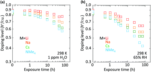
However, the spectator cation has a large influence on the doping stability, with the smaller cation conferring higher stability to the hole-doped state in the glovebox, when exposed to ambient conditions, and when heated. The doping level (DL) of 35 nm-thick TFB-CF3SIS-M films was measured by optical spectroscopy as a function of time in the N2 glovebox, or under ambient conditions (298 K, relative humidity RH 65%), and is shown in Fig. 4a and b, respectively. The optical spectra are shown in ESI,† Fig. S4a and b, respectively. These films were spin-cast from purified and self-compensated hole-doped solutions of the respective polymers in anhydrous acetonitrile. The DL was evaluated by transmission UV-Vis spectroscopy based on the loss in the intensity of the π–π* band (3.2 eV) and the gain in the intensity of the P2 polaron band (2.55 eV).16 All films exhibit a similar starting DL of ca. 0.85 h+ r.u.−1 (slightly lower for the larger cations), close to the saturation limit of 1 h+ r.u.−1, as a result of the use of an identical amount of oxidant, nitrosonium hexafluoroantimonate (1 mol equiv.), in their preparation. The WF is expected to depend only weakly on the doping level, down to 0.3 h+ r.u.−1 (ca. 90 meV per decade).16 So the change in the DL with time reflects the underlying stability of TFB-CF3SIS-M. The results show that the DL decays faster under ambient conditions than that in N2, and also faster for films with larger spectator cations. For example, the M = Li film (starting WF, 5.45 eV) decays to ca. 0.65 h+ r.u.−1 after 100 h under ambient conditions, but the M = NMe4 film (starting WF, 5.3 eV) decays to 0.4 h+ r.u.−1 The M = NEt4 film decays even faster (not shown).The decay in the DL arises from chemical hole trapping, i.e., hole transfer from the polymer backbone to the hydrated CF3SIS anion followed by annihilation, causing irreversible de-doping of the polymer, and generation of protons from water oxidation reaction, or of stable radicals from the follow-on reaction coupled to anion oxidation.18 Hydration occurs under ambient conditions because of the hygroscopicity of the ion clusters.17 The results here show that the smaller spectator cations suppress chemical hole trapping in the hydrated CF3SIS anion, despite the larger degree of hydration of their ion clusters.17
Origin of the spectator-ion effect on stability
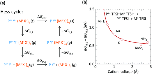
To understand how the spectator cation can exert such an effect, we consider the Hess cycle shown in Fig. 5a. This allows us to focus on the essential effects without explicit treatment of the entire ion cluster configuration space, i.e. geometry and arrangement of the ions. We consider that the hole-doped polymer P+˙ is counter-balanced by a local ion cluster Y− (M+ X−)q, where Y− represents the anion or the hydrated anion complex. For a fully hole-doped TFB-CF3SIS-M, q = 1–3, for the most important (n, m) clusters. We consider the effect of M+ in the following steps: (i) removal of the doped polymer segment P+˙ and its associated counter-balancing local ion cluster Y− (M+ X−)q from the solid matrix, leaving behind a cavity, with transformation Gibbs free energy ΔGd,1; followed by (ii) detachment of the spectator-ion cluster (M+ X−)q from the hole pair P+˙ Y−, with free energy ΔGid,1, which depends on M+; then (iii) hole transfer from P+˙ to Y− to give P Y˙, where Y˙ is the product of hole transfer, with free energy ΔGet,g, Y˙ may be a (hydrated) proton associated with X−, X−H, or a stable radical product from X− oxidation; then (iv) re-attachment of the (M+ X−)q to the neutral pair P Y˙, with free energy −ΔGid,2; then (v) re-embedding the entire cluster into the cavity in the matrix, with free energy −ΔGd,2.The Gibbs free energy for de-doping (ΔGet,s), i.e., transfer of the hole from P+˙ to Y− in the presence of M+ and its associated counter-anion in the solid state is then given by ΔGet,s = ΔGd,1 + ΔGid,1 + ΔGet,g − ΔGid,2 − ΔGd,2. ΔGid,1 − ΔGid,2 has strong dependence on M+, but not ΔGd,1 − ΔGd,2 nor ΔGet,g. Thus the spectator cation effect is dominated by the free energy of detachment ΔGid,1 (≫ΔGid,2) of P+˙ Y− from (X− M+)q, which may be a priori expected to increase with decreasing M+ size (and with decreasing cluster size q). To estimate ΔGid,1 − ΔGid,2, we examined a simple model system at the PM3 level: P+˙ TFSI− (M+ TFSI−)q → P+˙ TFSI− + (M+ TFSI−)q, where bis(trifluoromethanesulfonyl)imide is used as the simplest model for CF3SIS, and triphenylaminium for P+˙, for q = 1. First, we computed the corresponding dissociation internal energy for the simpler trion, TFSI− (M+ TFSI−)q → TFSI− + (M+ TFSI−)q, and then included the effects of P+˙ by translating the curve to match the results of configurations sampled in the quad-ion space. Neglecting the volume and entropy effects gives the Gibbs free energy difference, as shown in Fig. 5b. The results show that the smaller cations exhibit a larger ΔGid,1 − ΔGid,2, thus conferring higher stability to the hole-doped state. Li+ confers a stabilization of ca. 0.5 eV compared to NMe4+ or NEt4+. This is because Li+ has a higher charge density (smaller ionic radius) and can form specific ionic coordination with the oxygen atom in TFSI−. Thus the surprising spectator cation effect is associated with the notion that a smaller M+ increases the (positive) Coulomb potential at the anion site Y−, which in turn increases the energy cost for hole transfer to Y−.
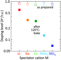
This trend persists in thermal stability. Fig. 6 shows that the M = Li film after baking to 120 °C retains a DL of 0.6 h+ r.u.−1, which is good enough to maintain the WF and injection properties of the film.16,18 Baking to 120 °C is sometimes required for device processing. In contrast, the M = NMe4 and NEt4 films fall to 0.12 and 0.07 h+ r.u.−1, respectively, which are no longer fit for purpose.
Device validation
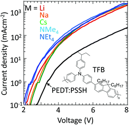
Finally, to confirm that these materials can indeed inject holes efficiently into large-ionization-energy (IE) organic semiconductors, the hole-doped TFB-CF3SIS-M polymers were tested as hole-injection layers (HILs) using TFB as the semiconductor in a hole-dominated device configuration: glass/ITO/HIL/100 nm TFB/Al. TFB has an IE of 5.5 eV. Hole-doped PEDT:PSSH, which has a WF of 5.2 eV, lies at the boundary of the blocking/injection behaviour for TFB.29Fig. 7 shows that the current density increases greatly by an order of magnitude when the hole-doped PEDT:PSSH is replaced by hole-doped TFB-CF3SIS-M, independent of M, because of Fermi level pinning.30,31 This shows that the TFB-CF3SIS-Li system may be a practical ultrahigh WF HIL. We further subjected the HIL films to thermal treatment at 120 °C, and the current density of Li, Na and Cs devices drops only by a factor of 2, for the NMe4 device by a factor of 4 and NEt4 by 1 order (ESI,† Fig. S5). The trend is in broad agreement with the earlier film baking treatment results (Fig. 6).Summary
We have demonstrated that although the size of the spectator cation has a marginal effect on workfunction, they are not innocent by-standers. They play an important role in the processing and film stability of the SC hole-doped polymers. We have related this to the Coulomb stabilization of the anion site due to the electrostatic potential of the cation. These new insights on the spectator cation provide useful design rules for the development of ambient stable self-compensated, hole-doped polymers with more extreme WFs.Methods
Materials: general
PEDT:PSSH (1![[thin space (1/6-em)]](https://www.rsc.org/images/entities/char_2009.gif) :
:![[thin space (1/6-em)]](https://www.rsc.org/images/entities/char_2009.gif) 6 wt/wt%), used as the reference in devices, was obtained from Clevios (P VP Al 4083, Heraeus Precious Metals GmbH) and was further purified by dialysis against 1 M semiconductor-grade HCl solution followed by Millipore® water through a 12 kDa molecular weight cutoff membrane to remove metallic ions and other acid impurities.19 Poly(9,9-dioctylfluorene-2,7-diyl-1,4-phenylene-N-(p-sec-butylphenyl)imino-1,4-phenylene) (TFB) was a gift from Cambridge Display Technology Ltd-Sumitomo Chemical Co (CDT-SCC).
6 wt/wt%), used as the reference in devices, was obtained from Clevios (P VP Al 4083, Heraeus Precious Metals GmbH) and was further purified by dialysis against 1 M semiconductor-grade HCl solution followed by Millipore® water through a 12 kDa molecular weight cutoff membrane to remove metallic ions and other acid impurities.19 Poly(9,9-dioctylfluorene-2,7-diyl-1,4-phenylene-N-(p-sec-butylphenyl)imino-1,4-phenylene) (TFB) was a gift from Cambridge Display Technology Ltd-Sumitomo Chemical Co (CDT-SCC).
Materials: TFB-CF3SIS-M
TFB-CF3SIS-Na was synthesized by following the procedure of Tang et al.14 and by dialysis through a regenerated cellulose membrane (molecular-weight cutoff, 12–14 kDa) in ACN to remove low molecular weight materials and ionic impurities. Different spectator cations (Li, Cs, NMe4 and NEt4) were then synthesized by the ion-exchange resin method. Amberlyst H resins15 (Sigma Aldrich) were first washed with deionized water until the washings gave pH 7. They were then converted to different cations by mixing with 1.5 mol equivalent of the respective hydroxides and put on a mechanical roller (3 h, 298 K, 65% RH) to give the desired M resins. The M resins were washed with deionized water until the washings gave pH 7, then rinsed and conditioned in ACN (16 h). TFB-CF3SIS-Na was dissolved in ACN in a vial to a concentration of 50 mg mL−1, 20 mol equivalent of the desired M resins was added, and the mixture was kept on a mechanical roller (6 h, 298 K, 65% RH). The solution was concentrated using a rotary evaporator and precipitated in diethyl ether. The solution was concentrated using rotary evaporator and precipitated in diethyl ether, and dried under vacuum. The completion of ion-exchange was confirmed by 1H NMR for tetraalkylammonium (DMSO-d6, 400 MHz, δ (ppm): NMe4, 3.07 (s, 24H); NEt4, 3.21–3.15 (q, 16H), 1.16–1.14 (t, 24H)), and X-ray photoemission spectroscopy (XPS) for other cations (see ESI,† Fig. S1). The Li sample was further evaluated by elemental analysis together with inductively coupled plasma optical emission spectrometry (ICP-OES). Atomic force microscopy shows the undoped TFB-CF3SIS-M films to be smooth with a root-mean-square (RMS) roughness of 2.6 Å to 4.7 Å (ESI,† Fig. S2).Self-compensated hole-doped TFB-CF3SIS-M
The purified TFB-CF3SIS-M polymer was baked at 120 °C (1 h) in a N2-glovebox (pO2, pH2O < 1 ppm) and dissolved in anhydrous ACN to a concentration of 15 mM. 1 mol equiv. of NOSbF6 (40 mM in anhydrous ACN) was added to give hole-doped TFB-CF3SIS-M solutions. The doped polymer was purified by precipitation with dimethyl carbonate twice to remove excess ions and impurities, and re-dissolved in ACN to give a 15 mM solution of the self-compensated hole-doped TFB-CF3SIS-M. This solution was spin-cast onto the desired substrates in the N2 glovebox to give a 35–40 nm-thick SC hole-doped TFB-CF3SIS-M film. Atomic force microscopy shows that the RMS roughness of the hole-doped TFB-CF3SIS-M films is higher and more varying compared to that of undoped films. The 3 × 3 μm RMS roughness of M = Li, Na, Cs and NMe4 and NEt4 films are 50, 15, 15, 8, and 8 Å, respectively, showing that the larger spectator cations confer better solubility to the hole-doped polymer (ESI,† Fig. S2).Ultraviolet and X-ray photoemission spectroscopy (UPS and XPS)
Undoped 20 nm-thick TFB-CF3SIS-M and also SC hole-doped TFB-CF3SIS-M films were prepared from their respective 10 mM solutions in ACN onto native Si substrates in the N2-glovebox. The doped films were transferred under N2 without exposure to air into the loading port of the XPS/UPS station. UPS was performed using He I radiation (21.21 eV) and a VG ESCALab Mk-II spectrometer operating at a base pressure of 1 × 10⁻⁹ mbar. A sample bias of −5.00 V was applied to collect all the photoemission. XPS was performed on the same films as in UPS, after UPS, using MgKα X-ray (1253.6 eV), respectively, on a VG ESCALab Mk-II spectrometer, at 90° acceptance angles (with respect to the analyzer).Film-state UV-visible spectroscopy
35 nm-thick undoped TFB-CF3SIS-M and SC hole-doped TFB-CF3SIS-M films were prepared from their respective 15 mM solutions in ACN onto O2-plasma-cleaned glass substrates in a N2-glovebox. UV-Vis spectroscopy was performed using an Ocean Optics S1024DW Deep Well spectrometer with a DH-2000 deuterium tungsten halogen light source. Measurements were taken with an integration time of 35 ms over an average of 100 scans from 350–960 nm.Molecular dynamics simulation
Classical molecular dynamics (MD) simulation was performed using the AMBER package26 and the generalised AMBER force field.27 We used 10 polymer chains with 4 polymer repeat units per chain randomly placed in a large empty box with periodic boundary conditions. The doped polymer has 1 hole-charge per repeat unit. The charges on each atom of the polymer chain for both the doped and undoped cases were obtained following the RESP method,28 by fitting to the electrostatic potential calculated using the HF/6-31G(d) basis set. 40 or 80 Na spectator cations were added to represent the fully doped and undoped states, respectively. These starting configurations were compressed to their densities by a 3 ns MD run with an external pressure of 1 bar. The compressed structures were used as an input for a 7.5 ns equilibration and 7.5 ns production run at 300 K. Only the production trajectory was used for statistical averaging. The TFB-CF3SIS-M densities were determined by the flotation method to be 1.45, 1.40, 1.61, 1.28 and 1.28 g cm−3 for M = Li, Na, Cs, NMe4 and NEt4, respectively. To obtain these densities, undoped TFB-CF3SIS-M films were drop-cast onto O2-plasma-cleaned native silicon oxide wafers, and annealed in the N2-glovebox at 200 °C for 10 min before exposing to ambient conditions. The film was removed from its wafer and placed into tetralin (1 mL, 0.97 g cm−3). Carbon tetrachloride (1.59 g cm−3) was added to give a density increase in steps of 0.02 g cm−3. Centrifugation at 3000 rpm (120 s) was used to accelerate sedimentation or flotation. The film density was taken to be that of the solvent mixture at the transition to flotation. For TFB-CF3SIS-Cs, a mixture of tetralin and 1,2-dibromoethane (2.17 g cm−3) was used to extend the density range.Devices
Dialyzed 1![[thin space (1/6-em)]](https://www.rsc.org/images/entities/char_2009.gif) :
:![[thin space (1/6-em)]](https://www.rsc.org/images/entities/char_2009.gif) 6 PEDT
6 PEDT![[thin space (1/6-em)]](https://www.rsc.org/images/entities/char_2009.gif) :
:![[thin space (1/6-em)]](https://www.rsc.org/images/entities/char_2009.gif) PSSH was deposited from a pre-filtered (0.45 μm nylon syringe filter) solution under ambient conditions on O2-plasma cleaned ITO substrates and then annealed at 140 °C (hotplate) for 10 min in a N2-glovebox to obtain the reference 45 nm-thick PEDT:PSSH film. SC hole-doped TFB-CF3SIS-M was spin-cast from 15 mM ACN solutions on O2-plasma cleaned ITO substrates to obtain 30 nm-thick HILs, with or without further baking at 120 °C 5 min in the N2-glovebox. 100 nm-thick TFB was spin-cast from 15 mg mL−1 toluene solution over the HILs in the N2-glovebox. 120 nm-thick Al was thermally-evaporated as the cathode layer through a shadow mask at a base pressure of 10−7 Torr to obtain the cathode for eight 4.3 mm2 pixels on each substrate.
PSSH was deposited from a pre-filtered (0.45 μm nylon syringe filter) solution under ambient conditions on O2-plasma cleaned ITO substrates and then annealed at 140 °C (hotplate) for 10 min in a N2-glovebox to obtain the reference 45 nm-thick PEDT:PSSH film. SC hole-doped TFB-CF3SIS-M was spin-cast from 15 mM ACN solutions on O2-plasma cleaned ITO substrates to obtain 30 nm-thick HILs, with or without further baking at 120 °C 5 min in the N2-glovebox. 100 nm-thick TFB was spin-cast from 15 mg mL−1 toluene solution over the HILs in the N2-glovebox. 120 nm-thick Al was thermally-evaporated as the cathode layer through a shadow mask at a base pressure of 10−7 Torr to obtain the cathode for eight 4.3 mm2 pixels on each substrate.
Conflicts of interest
There are no conflicts to declare.Acknowledgements
This research was supported by the National Research Foundation, Prime Minister's Office, Singapore, under its Competitive Research Programme (CRP Award No. NRF CRP 11-2012-03: R-144-000-339-281, R-143-000-608-281). M. C. A. and C. G. T. thank the Solar Energy Research Institute of Singapore (SERIS) for scholarships. SERIS sponsored by the National University of Singapore and Singapore's National Research Foundation through the Singapore Economic Development Board.References
- A. Garcia, J. Z. Brzezinski and T. Q. Nguyen, J. Phys. Chem. C, 2009, 113(7), 2950 CrossRef CAS.
- J. H. Seo, A. Gutacker, B. Walker, S. Cho, A. Garcia, R. Q. Yang, T. Q. Nguyen, A. J. Heeger and G. C. Bazan, J. Am. Chem. Soc., 2009, 131, 19220 Search PubMed.
- C. He, C. Zhong, H. Wu, R. Yang, W. Yang, F. Huang, G. C. Bazan and Y. Cao, J. Mater. Chem., 2010, 20, 2617 RSC.
- J. H. Seo, A. Gutacker, Y. Sun, H. Wu, F. Huang, Y. Cao, U. Scherf, A. J. Heeger and G. C. Bazan, J. Am. Chem. Soc., 2011, 133, 8416 CrossRef CAS PubMed.
- P. K. H. Ho, M. Granström, R. H. Friend and N. C. Greenham, Adv. Mater., 1998, 10, 769 CrossRef CAS.
- P. K. H. Ho, J. S. Kim, J. H. Burroughes, H. Becker, S. F. Y. Li, T. M. Brown, F. Cacialli and R. H. Friend, Nature, 2000, 404, 481 CrossRef CAS.
- R. Q. Yang, A. Garcia, D. Korystov, A. Mikhailovsky, G. C. Bazan and T. Q. Nguyen, J. Am. Chem. Soc., 2006, 128(51), 16532 CrossRef CAS.
- R. Q. Yang, H. B. Wu, Y. Cao and G. C. Bazan, J. Am. Chem. Soc., 2006, 128(45), 14422 CrossRef CAS.
- Y. Jin, G. C. Bazan, A. J. Heeger, J. Y. Kim and K. Lee, Appl. Phys. Lett., 2008, 93(12), 346 CrossRef.
- W. Shi, S. Fan, F. Huang, W. Yang, R. Liu and Y. Cao, J. Mater. Chem., 2006, 16(24), 2387 RSC.
- C. K. Mai, H. Q. Zhou, Y. Zhang, Z. B. Hension, T. Q. Nguyen, A. J. Heeger and G. C. Bazan, Angew. Chem., Int. Ed., 2013, 52, 12874 CrossRef CAS PubMed.
- C. K. Mai, R. A. Schlitz, G. M. Su, D. Spitzer, X. Wang, S. L. Fronk, D. G. Cahill, M. L. Chabinyc and G. C. Bazan, J. Am. Chem. Soc., 2014, 136(39), 13478 CrossRef CAS.
- W. L. Seah, C. G. Tang, R. Q. Png, V. Keerthi, C. Zhao, H. Guo, J. G. Yang, M. Zhou, P. K. H. Ho and L. L. Chua, Adv. Funct. Mater., 2017, 1606291 CrossRef.
- C. G. Tang, M. C. Y. Ang, K. K. Choo, V. Keerthi, J. K. Tan, M. Nur Syafiqah, T. Kugler, J. H. Burroughes, R. Q. Png, L. L. Chua and P. K. H. Ho, Nature, 2016, 539, 536 CrossRef CAS PubMed.
- M. C. Y. Ang, C. G. Tang, Q. M. Koh, C. Zhao, Q. J. Seah, Y. Wang, M. Callsen, Y. P. Feng, R. Q. Png and L. L. Chua, 2019, submitted.
- R. Q. Png, M. C. Y. Ang, M. H. Teo, K. K. Choo, C. G. Tang, D. Belaineh, L. L. Chua and P. K. H. Ho, Nat. Commun., 2016, 7, 11948 CrossRef CAS PubMed.
- C. G. Tang, M. C. Y. Ang, K. K. Choo, L. L. Chua, R. Q. Png and P. K. H. Ho, 2019, submitted.
- C. G. Tang, Q. M. Koh, M. C. Y. Ang, K. K. Choo, Q. J. Seah, L. L. Chua, R. Q. Png and P. K. H. Ho, 2019, submitted.
- P. J. Chia, S. Sivaramakrishnan, M. Zhou, R. Q. Png, L. L. Chua, R. H. Friend and P. K. H. Ho, Phys. Rev. Lett., 2009, 102, 0966021 CrossRef PubMed.
- D. Belaineh, R. Q. Png, C. L. McGuiness, M. Mathai, V. Seshadri and P. K. H. Ho, Chem. Mater., 2014, 26, 4724 CrossRef CAS.
- H. Tissot, G. Olivieri, J. J. Gallet, F. Boumel, M. G. Silly, F. Sirotti and F. Rochet, J. Phys. Chem. C, 2015, 119, 9253 CrossRef CAS.
- N. Ottosson, J. Heyda, E. Wernersson, W. Pokapanich, S. Svensson, B. Winter, G. Öhrwall, P. Jungwirth and O. Björneholm, Phys. Chem. Chem. Phys., 2010, 12, 10693 RSC.
- F. Y. Kam, R. Q. Png, M. C. Y. Ang, P. Kumar, Km. Rubi, R. Mahendiran, O. Solomeshch, N. Tessler, G. K. Lim, L. L. Chua and P. K. H. Ho, Mater. Horiz., 2017, 4, 456 RSC.
- A. Kahn, Mater. Horiz., 2016, 3(1), 7 RSC.
- V. I. Arkhipov and P. Heremanns, Phys. Rev. B: Condens. Matter Mater. Phys., 2005, 71, 045214 CrossRef.
- D. A. Case, T. E. Cheatham, T. Darden, H. Gohlke, R. Luo, K. M. Merz, A. Onufriev, C. Simmerling, B. Wang and R. Woods, J. Comput. Chem., 2005, 26, 1668 CrossRef CAS.
- J. M. Wang, R. M. Wolf, J. W. Caldwell, P. A. Kollman and D. A. Case, J. Comput. Chem., 2004, 25(9), 1157 CrossRef CAS.
- C. I. Bayly, P. Cieplak, W. Cornell and P. A. Kollman, J. Phys. Chem., 1993, 97(40), 10269 CrossRef CAS.
- M. Zhou, R. Q. Png, S. Sivaramakrishnan, P. J. Chia, C. K. Yong, L. L. Chua and P. K. H. Ho, Appl. Phys. Lett., 2012, 97, 113505 CrossRef.
- N. Koch, Chem. Phys. Chem., 2007, 8, 1438 CrossRef CAS.
- J. H. Huang, A. Wang and A. Kahn, Mater. Sci. Eng., R, 2009, 64, 1 CrossRef.
Footnote |
| † Electronic supplementary information (ESI) available. See DOI: 10.1039/c9tc03884a |
| This journal is © The Royal Society of Chemistry 2020 |

