Controlling the ambipolarity of thieno-benzo-isoindigo polymer-based transistors: the balance of face-on and edge-on populations†
Jungho
Lee‡
a,
Eun-Sol
Shin‡
b,
Yeon-Ju
Kim
c,
Yong-Young
Noh
*b and
Changduk
Yang
 *a
*a
aDepartment of Energy Engineering, School of Energy and Chemical Engineering, Perovtronics Research Center, Low Dimensional Carbon Materials Center, Ulsan National Institute of Science and Technology (UNIST), Ulsan 44919, Republic of Korea. E-mail: yang@unist.ac.kr
bDepartment of Chemical Engineering, Pohang University of Science and Technology, 77 Cheongam-Ro, Nam-Gu, Pohang 37673, Republic of Korea. E-mail: yynoh@postech.ac.kr
cResearch Institute for Solar and Sustainable Energies (RISE), Heeger Center for Advanced Materials (HCAM), School of Materials Science and Engineering (MSE), Gwangju Institute of Science and Technology (GIST), 123 Cheomdan-gwagiro Buk-gu, Gwangju 61005, Republic of Korea
First published on 25th November 2019
Abstract
In spite of its interesting ‘asymmetric’ polar cyclic amide structure combining the dual properties of isoindigo (IIG) and thieno-isoindigo, the recently formulated thieno-benzo-isoindigo (TBIG) has been less explored as a building block for organic electronic materials in conjugated polymers. This article introduces the results obtained on TBIG-based polymers (PTBIG-100, PTBIG-75, PTBIG-50, and PTBIG-25) having different ratios of TBIG and IIG accepting units and a bithiophene counterpart donor to highlight their fundamental characteristics in terms of the organic field-effect transistor (OFET) mobilities. Besides, an increase in the TBIG unit results in increased co-planarity, red-shifted absorption, and higher-lying highest occupied molecular orbital levels as well as higher face-on crystallite populations relative to edge-on ones. All the polymer-based OFETs exhibit ambipolar charge transport properties; PTBIG-100 adopting a highly face-on orientation exhibits the highest hole mobility of 0.13 cm2 V−1 s−1 but rather low electron mobility, while the opposite is true for PTBIG-25 having a higher edge-on one. Besides, highly balanced hole and electron mobilities (μFET,h = 0.06 cm2 V−1 s−1 and μFET,e = 0.045 cm2 V−1 s−1) are observed for PTBIG-75 with a similar population between face-on and edge-on textures. Analysis of the electrical and structural properties in this study demonstrates that the ratio of face-on and edge-on is a key factor in not only determining the dominant polarity, but also achieving balanced ambipolarity in OFETs.
Introduction
Organic field-effect transistors (OFETs) based on π-conjugated polymers are of particular interest as the basic elements for circuits used in flexible active-matrix displays, radio frequency identification (RFID) tags, electronic paper, and other printed electronic devices.1–6 With current rapid progress in the development of state-of-the-art π-conjugated polymers, high-performance p-channel, n-channel, and even ambipolar OFETs with excellent mobility and stability have been reported.7–11 Many studies demonstrate that appropriate connection of donor–acceptor moieties is a viable approach to create high-performance polymers in OFETs by taking advantage of intermolecular donor and acceptor interactions that are preferable for charge carrier transport through the intermolecular hopping mechanism.12 The incorporation of ‘symmetric’ dyes with polar cyclic amide and diimide structures, such as diketopyrrolopyrrole (DPP),13–17 isoindigo (IIG)8,18–22 and thienoisoindigo (TIG),10,23–25 naphthalenediimide (NDI),26–30 and perylenediimides (PDI),31–34 has been established as a very effective way to combine strong accepting properties with a tendency to provide close intermolecular packing through dipolar interactions. Such dye-containing successful polymers have been reported, showing impressive hole and electron OFET mobilities and even excellent ambipolar behaviors.7–10Very recently, Fréchet and coworkers reported the synthesis of a brand-new thieno-benzo-isoindigo (TBIG) dye in which one single phenyl ring of IIG is replaced with thiophene, and polymers containing it.25 Similar to the aforementioned dyes, TBIG is a polar cyclic amide structure as a thiophene analogue of IIG, yet an ‘asymmetric’ unit, and combines the dual properties of IIG and TIG. Despite having such unique structure features, up to now, TBIG-based polymers have been reported very little for use in optoelectronic devices.25,35–38
The present article describes the synthesis and characterization as well as OFET characteristics of a collection of TBIG-based polymers (PTBIG-100, PTBIG-75, PTBIG-50, and PTBIG-25) with varied compositions of TBIG and IIG accepting segments and a bithiophene counterpart donor. We found that the essential properties including not only their absorption, frontier energy levels, morphology, and molecular orientation but also the carrier mobility and dominant polarity in OFETs are strongly related to the loading ratios of TBIG and IIG. Concretely, the PTBIG-100 film (no IIG unit) has a large propensity to form a face-on orientation, showing the highest hole mobility of up to 0.13 cm2 V−1 s−1 but rather low electron mobility, whereas introduction of IIG into the backbone leads to an increased edge-on population and electron mobility. Besides, it is worthy of note that PTBIG-75 has an almost half-and-half ratio of the face-on and edge-on orientations, affording highly balanced hole and electron mobilities (μFET,h = 0.06 cm2 V−1 s−1 and μFET,e = 0.045 cm2 V−1 s−1). Overall, these results reveal that the degree of face-on and edge-on orientation can highly contribute to the dominant polarity and balanced ambipolar nature of the conjugated polymers.
Results and discussion
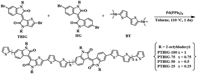
Two dibrominated TBIG and IIG monomers were prepared according to previous literature.25 As shown in Scheme 1, all the polymers were prepared under identical polymerization via Stille coupling by using the catalyst Pd(PPh3)4 with bis(trimethylstannyl)bithiophene (BT) as a counterpart donor co-monomer in toluene for 1 day. To investigate the relationship between the composition and properties of the resulting polymers, the feed ratios of TBIG to IIG in the polymer backbone are varied as 100%, 75%, 50%, and 25%, denoted as PTBIG-100, PTBIG-75, PTBIG-50, and PTBIG-25. All the polymers were purified via sequential Soxhlet extraction using methanol, acetone, and n-hexane to remove the oligomers and other impurities. Then, chloroform was employed to elute the refined polymers and re-precipitation in methanol yielded the desired products. More detailed polymerization procedures and characterization are described in the Experimental section. The average molecular weights (Mn) and polydispersity index (PDI) were determined using high-temperature gel-permeation chromatography (HT-GPC) at 100 °C with 1,2,4-trichlorobenzene as the eluent. PTBIG-100, PTBIG-75, PTBIG-50, and PTBIG-25 had sufficiently high Mn of 18.6, 18.0, 29.8, and 26.4 kDa, respectively, with narrow PDI values of 1.81–2.45, minimizing the errors from different molecular weight effects on the electrical properties. All the polymers have high solubility in common organic solvents such as chloroform and chlorobenzene.To simulate the geometry-optimized structures, density functional theory (DFT) calculations for two models with alternative sequences ((TBIG–BT)2 and (IIG–BT)2) were performed using Gaussian 09 using the hybrid B3LYP correlation functional and 6-31G* basis set (Fig. 1a and b), where methyl groups were used instead of 2-octyldodecyl chains to reduce the computational time. For (IIG–BT)2, the intramolecular twisting angle (θ1) within the IIG segment and inter-monomeric torsion angle (θ2) between the IIG and BT subunits is 4.09° and 15.46°, respectively, while much smaller dihedral angles (θ1 = 0.09° and θthienyl2 and θpheyl2 = 1.09° and 12.49°) were observed in (TBIG–BT)2. Note that in the case of (TBIG–BT)2, the presence of two inter-monomeric torsion angles is a result of the asymmetric structure of TBIT; θthienyl2 and θpheyl2 are the torsion angles of the thienyl and phenyl substituents of TBIG and BT, respectively. These results suggest that the backbone co-planarity of the synthesized polymers can be increased with increasing the TBIG content, expecting benefits for the OFET performance (i.e., tight molecular packing and extended effective conjugation length).
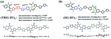 | ||
| Fig. 1 The intramolecular twisting and inter-monomeric torsion angles with front/side geometries from the DFT calculations at the B3LYP/6-31G* level based on (a) (TBIG–BT)2 and (b) (IIG–BT)2. | ||
In addition, to explore the electron density distributions and energy levels as a function of different ratios of TBIG and IIG units in the polymer backbone, we also carried out DFT calculations of tetrameric models (TBIG–BT)4, (TBIG–BT)3–(IIG–BT)1, (TBIG–BT)2–(IIG–BT)2, and (TBIG–BT)1–(IIG–BT)3 (see Fig. S1, ESI†). The HOMO/LUMO energies of (TBIG–BT)4, (TBIG–BT)3–(IIG–BT)1, (TBIG–BT)2–(IIG–BT)2, and (TBIG–BT)1–(IIG–BT)3 were calculated to be −4.79/−3.20, −4.85/−3.18, −4.88/−3.16, and −4.92/−3.17 eV, respectively. Notably, it is apparent that the electron densities of the HOMO and LUMO are more delocalized along the entire conjugated backbones with increasing TBIG–BT fraction, which is beneficial for charge carrier transport.
To investigate the optical properties of the TBIG-based polymers, UV-vis absorption spectra were measured in dilute chloroform solution (Fig. 2a) and films (Fig. 2b), and relevant data are collected in Table 1. All the absorption spectra of the TBIG-based polymers exhibited two distinctive absorption bands between 350 and 500 nm and 600 and 900 nm; the former one is known as π–π* transitions and the latter one is the intramolecular charge transfer (ICT) between the D and A segments. Increasing the TBIG concentration results in a gradual red shift of the absorption maximum (λmax) of the ICT band, indicating higher backbone co-planarity of TBIG relative to IIG, which is well-consistent with the DFT calculations above. The PTBIG-100 polymer with an alternating sequence shows a slight red shift (8 nm) like a previous study,25 while the others with random sequences present moderate blue shifts (6–8 nm) due to the effect of the IIG segment. The optical bandgaps (Eoptg) of the polymers were estimated from the onset of the ICT bands in the films, providing the following trend: PTBIG-100 (1.33 eV) < PTBIG-75 (1.37 eV) < PTBIG-50 (1.40 eV) < PTBIG-25 (1.44 eV).
 | ||
| Fig. 2 UV-vis absorption spectra of TBIG-based polymers (a) in dilute chloroform solution and (b) in films; (c) molecular energy level diagrams of the materials in this work. | ||
| Polymer | λ solutionmax [nm] | λ filmmax [nm] | λ filmonset [nm] | E optg [eV] |
|---|---|---|---|---|
| PTBIG-100 | 790 | 798 | 931 | 1.33 |
| PTBIG-75 | 750 | 742 | 904 | 1.37 |
| PTBIG-50 | 722 | 716 | 886 | 1.40 |
| PTBIG-25 | 712 | 706 | 862 | 1.44 |
The electrochemical behaviours and electronic energy levels of the polymers were investigated by cyclic voltammetry (CV) (Fig. S2, ESI†). The polymer films were coated on a platinum working electrode, and their CV diagrams were recorded in an acetonitrile solution containing 0.1 M n-Bu4NPF6 under an inert atmosphere versus the Ag/Ag+ redox couple. The HOMO and LUMO energy levels of the polymers were obtained from the equation EHOMO (eV) = −(Eonset(ox) − Eonset(ferrocene) + 4.8) and ELUMO (eV) = −(Eonset(red) − Eonset(ferrocene) + 4.8), respectively. The estimated HOMO/LUMO energy levels of the polymers are depicted as energy level diagrams in Fig. 2c. It is apparent that although the composition variations of TBIG and IIG subunits have little impact on the LUMO values of the polymers, the HOMO values rise gradually with an increasing TBIG portion, resulting from the increased electron donating characteristics and co-planarity when the phenyl rings in IIG are replaced by the more electron-rich and less sterically demanding thiophene unit in TBIG.25 The electrochemical bandgaps (ECVgs) gathered from CV measurements are in good agreement with the Eoptg trends discussed above.
The top-gate/bottom-contact configuration of OFETs was made by the TBIG-based polymers with pre-patterned Au/Ni electrodes and a PMMA dielectric layer was deposited by spin-coating onto the active layer. All the OFET devices were annealed at the optimized temperature of 250 °C for 30 min. More detailed fabrication processes are provided in the Experimental section. Representative transfer curves of the OFETs based on the series of TBIG-based polymers for p-type and n-type operation are shown in Fig. 3a and b respectively. All the device parameters extracted from the saturation regime (VD = −80 V) are summarized in Table 2. Modulation of the charge transport characteristics occurred in accordance with the increased portion of the IIG segment in the polymer backbone. The OFET made with PTBIG-100 showed the highest hole mobility (μFET,h) of up to 0.13 cm2 V−1 s−1, whereas the electron mobility (μFET,e) exhibited rather worse OFET performance at 0.009 cm2 V−1 s−1. Very interestingly, incorporating the IIG unit into the backbone caused a dramatic enhancement of the electron mobilities, accompanied by decreased hole mobilities. As a result, PTBIG-50 and PTBIG-25 showed the inverse dominant polarity (i.e., n-channel dominant OFETs) with significantly improved electron mobilities of 0.023 cm2 V−1 s−1 and 0.026 cm2 V−1 s−1 compared to PTBIG-100, respectively. In the meantime, PTBIG-75 achieved the most balanced ambipolar mobilities (μFET,h = 0.06 cm2 V−1 s−1 and μFET,e = 0.045 cm2 V−1 s−1) with ambipolarity (μFET,h/μFET,e) up to 1.33.
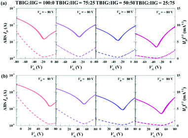 | ||
Fig. 3 Transfer characteristics of (a) p-type and (b) n-type for TBIG![[thin space (1/6-em)]](https://www.rsc.org/images/entities/char_2009.gif) : :![[thin space (1/6-em)]](https://www.rsc.org/images/entities/char_2009.gif) IIG ratios of 100 IIG ratios of 100![[thin space (1/6-em)]](https://www.rsc.org/images/entities/char_2009.gif) : :![[thin space (1/6-em)]](https://www.rsc.org/images/entities/char_2009.gif) 0, 75 0, 75![[thin space (1/6-em)]](https://www.rsc.org/images/entities/char_2009.gif) : :![[thin space (1/6-em)]](https://www.rsc.org/images/entities/char_2009.gif) 25, 50 25, 50![[thin space (1/6-em)]](https://www.rsc.org/images/entities/char_2009.gif) : :![[thin space (1/6-em)]](https://www.rsc.org/images/entities/char_2009.gif) 50, and 25 50, and 25![[thin space (1/6-em)]](https://www.rsc.org/images/entities/char_2009.gif) : :![[thin space (1/6-em)]](https://www.rsc.org/images/entities/char_2009.gif) 75 in OFETs. 75 in OFETs. | ||
| Polymer | μ FET,h [cm2 V−1 s−1] | μ FET,e [cm2 V−1 s−1] | Ambipolarity [μFET,h/μFET,e] | V T,h [V] | V T,e [V] | R c·Wh [MΩ cm] | R c·We [MΩ cm] | E A [meV] |
|---|---|---|---|---|---|---|---|---|
| PTBIG-100 | 0.13 ± 0.05 | 0.009 ± 0.002 | 14.44 | 47.8 | 50.0 | 0.36 | 762 | 115.05 |
| PTBIG-75 | 0.06 ± 0.02 | 0.045 ± 0.010 | 1.33 | 35.5 | 55.8 | 0.58 | 147 | 122.20 |
| PTBIG-50 | 0.008 ± 0.003 | 0.023 ± 0.007 | 0.35 | 30.5 | 52.8 | 5.1 | 257 | 173.12 |
| PTBIG-25 | 0.004 ± 0.001 | 0.026 ± 0.005 | 0.015 | 28.4 | 52.3 | 41.6 | 550 | 192.60 |
For the investigation of the device stability, the bias stress and air stability were measured for the TBIG-based OFETs respected to p-type characteristics (Fig. 4a and b). The drain current versus time depending on the TBIG/IIG ratio shows a dramatic degradation of the drain current under bias stress. The contact resistance (RC) between the S/D electrodes and the TBIG-based polymer films can be evaluated by the output characteristics in the linear regime and the Y-function method (Fig. S3, ESI†).39,40 As the ratio of the IIG segment increases, RC,h is increased by 100 times from 0.36 MΩ cm of PTBIG-100 to 41.6 MΩ cm of PTBIG-25, and the lowest RC,h value of PTBIG-100 is one of the clear reasons for the highest hole mobility in OFETs. These results are consistent with the correlation between the energy level of the gold electrode and the HOMO levels according to the ratio change of TBIG and IIG. In terms of electrons, PTBIG-75 exhibited the lowest contact resistance at 147 MΩ cm, leading to the highest electron mobility among the series of TBIG-based polymers. A little change in the intrinsic properties such as the lowest LUMO level of PTBIG-75 at −3.64 eV might give a clue to elucidate the observed difference in electron mobility, however, it is still insufficient to explain this. Hence, it might be related to the molecular ordering and crystalline properties.
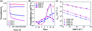 | ||
| Fig. 4 (a) Normalized bias stability and (b) air stability of TBIG-based polymer OFETs; (c) field-effect mobility in the linear regime versus temperature of PTBIG-based polymers. | ||
To obtain more understanding of the effects on charge transport, we performed low-temperature measurements based on all the series of TBIG-based polymer OFETs. Because the charge carrier mobilities of conjugated polymers occurred through thermally activated hopping in localized states, thus the activation energy (EA) can be calculated as follows:
To investigate the molecular ordering and crystalline properties of the TBIG-based polymers, atomic force microscopy (AFM) and 2D-grazing incidence X-ray diffraction (2D-GIXD) were carried out. AFM images in phase mode were measured to confirm the surface morphologies of the films with all the ratios of TBIG:IIG. All the films showed smooth surfaces, but the root mean square roughness of the films is increased a little bit on increasing the IIG segment from 0.47 nm to 0.81 nm (Fig. S4, ESI†).
Fig. 5a and Fig. S5 (ESI†) show 2D-GIXD patterns and 1D-profiles of the polymer films based on the PTBIG series with thermal annealing treatment for 10 minutes at 250 °C. All the PTBIG series show similar diffraction peaks along the out-of-plane and in-plane direction, as well as similar lamella d-spacing distances and π–π stacking distances. The lamella d-spacing distances are calculated from the (100) peak at q ≈ 0.29 Å−1 in the out of plane direction as 22.2 Å, and the π–π stacking distances are derived from the (010) peak at q ≈ 1.67 Å−1 in the out of plane direction as 3.76 Å. Interestingly, the strong (010) diffraction peak in the out of plane direction observed from PTBIG-100 gradually faded with growing the portion of the IIG segment in the polymer backbone. On the contrary, the lamellar (h00) peaks in the out of plane direction are clearly steady with an IIG segment increase against the TBIG segment. From these results, we can expect changes of the crystallinity structure from strong face-on orientation to edge-on dominant textures with the increasing ratio of the IIG segment.
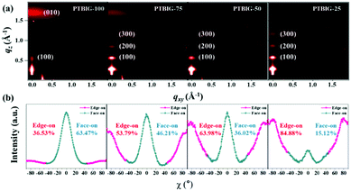 | ||
| Fig. 5 (a) 2D-GIXD image of TBIG-based polymer films; (b) pole figure extracted from the (010) diffraction peaks of PTBIG-based polymer films. | ||
The intensity-corrected pole figure plot based on the (010) diffraction peaks is used to investigate the crystallite orientation distribution in Fig. 5b. The area can be divided by χ = 0° ± 45° and χ = ± 45° ± 90° to calculate quantitatively the face-on and edge-on crystallinity structure, respectively. PTBIG-100 clearly shows a face-on dominant distribution (face-on: 63.47% and edge-on: 36.53%), but PTBIG-50 and PTBIG-25 exhibit an edge-on dominant distribution. On the other hand, the PTBIG-75 film is of almost half-and-half of face-on and edge-on packing orientations, which might make room for a three-dimensional charge conduction channel for electrons and holes, resulting in the most balanced ambipolarity in the OFET performances. These findings suggest that the polymer chain orientation plays a crucial role in determining the balanced ambipolarity of polymers.
Conclusions
In summary, we have synthesized and characterized a series of TBIG-based polymers (PTBIG-100, PTBIG-75, PTBIG-50, and PTBIG-25) composed of different feed ratios between TBIG and IIG accepting segments and a bithiophene counterpart donating unit. The resultant polymers with higher TBIG contents exhibit increased backbone co-planarity, red-shifted absorption, and higher-lying HOMO levels. Besides, the 2D-GIXD pattern images and intensity-corrected pole figure plot elucidate striking changes of the dominant packing orientation from face-on to edge-on depending on the composition of TBIG and IIG units; the edge-on crystallite populations relative to the face-on ones are in the order of PTBIG-100 < PTBIG-75 < PTBIG-50 < PTBIG-25. In OFET tests, all the polymers display ambipolar behaviors; PTBIG-100 with a higher face-on alignment shows the best hole mobility of 0.13 cm2 V−1 s−1 yet rather low electron mobility, while PTBIG-25 with a higher edge-on alignment displays the best electron mobility of 0.026 cm2 V−1 s−1 yet reduced hole mobility. More interestingly, we find that PTBIG-75 adopting almost half-and-half face-on and edge-on packing orientations shows highly balanced hole and electron mobility (μFET,h = 0.06 cm2 V−1 s−1 and μFET,e = 0.045 cm2 V−1 s−1). Consequently, these findings provide relevant study subjects for establishing a correlation between molecular orientation and ambipolar device performance.Experimental section
Materials and characterization
All starting materials were purchased from Aldrich and Acros and used without further purification. All solvents are of ACS grade unless otherwise noted. 1H NMR and 13C NMR spectra were recorded on a VNMRS 400 MHz spectrophotometer using CDCl3 as the solvent and tetramethylsilane (TMS) as the internal standard. UV-vis spectra were recorded on a Cary 5000 (Varian USA) spectrophotometer. The optical bandgaps were estimated from the absorption onset of the as-cast thin films. The number-average (Mn) and weight average (Mw) molecular weights, and polydispersity index (PDI) of the polymer products were determined by gel permeation chromatography (GPC) with a Waters 150C GPC using a series of mono disperse polystyrene as standards in 1,2,4-trichlorobenzene (HPLC grade) at 100 °C. Cyclic voltammetry (CV) measurements were performed on a Solartron electrochemical station (METEK, Versa STAT3) with a three-electrode cell in a 0.1 M tetra-n-butylammonium hexafluorophosphate (n-Bu4NPF6) solution in acetonitrile at a scan rate of 100 mV s−1 at room temperature under argon. An Ag/Ag+ electrode, a platinum wire, and a platinum electrode were used as the reference electrode, counter electrode, and working electrode, respectively. The Ag/Ag+ reference electrode was calibrated using a ferrocene/ferrocenium redox couple as an external standard, whose oxidation potential is set at 4.8 eV with respect to a zero vacuum level. The HOMO energy levels were obtained from the equation HOMO (eV) = −(Eonset(ox) − Eonset(ferrocene) + 4.8). The LUMO levels of the polymers were obtained from the equation LUMO (eV) = −(Eonset(red) − Eonset(ferrocene) + 4.8). OFETs with a top-gate/bottom-contact configuration were fabricated on glass substrates with a prepatterned Au/Ni electrode by using conventional photolithography processes. The glass substrates were cleaned with deionized water, acetone and isopropanol solution for 10 min in an ultrasonic bath, respectively. The solutions of all PTBIG-100, 75, 50 and 25 were prepared using dichlorobenzene solvent with a 5 mg ml−1 concentration and were spin coated at 2000 rpm for 60 s on the substrates. In an N2-filled glove box, all the coated films were thermally annealed at 250 °C for 30 min and polymethylmethacrylate (PMMA, Aldrich, Mw = 120 kDa) polymer in n-butyl acetate at 80 mg ml−1 was filtered using a 0.45 μm polytetrafluoroethylene syringe filter and spin coated on the PTBIG polymer at 2000 rpm for 60 s as a dielectric layer in an N2-filled glove box. After then all samples were thermally annealed at 80 °C for 2 h in the same atmosphere. For the gate electrode, Al was deposited on the active position with a shadow mask using thermal evaporation (∼50 nm thick). The electrical characteristics of the OFETs were measured using a semiconductor characterization system (Keithley 4200-SCS) in an N2-filled glove box. The field-effect mobility (μFET) and threshold voltage (VT) were calculated by equations for classical silicon metal–oxide–semiconductor field-effect transistors in the saturation regime. For a low temperature measurement system, the same condition of electrical characteristics and a vacuum chamber were used and liquified nitrogen gas was used to reduce the temperature. The surface morphology of the TBIG:IIG semiconducting polymer was investigated using atomic force microscopy (AFM) in tapping-mode (Nanoscope III, Veeco Instruments, Inc.), and 2D-grazing incidence X-ray diffraction (2D-GIXD) performed using 11.17 keV X-rays at Beamline 9A at the Pohang Accelerator Laboratory. All films were prepared under the same conditions as the above device fabrication.Polymerization methods
Conflicts of interest
There are no conflicts to declare.Acknowledgements
This work was supported by a National Research Foundation of Korea (NRF) grant funded by the Korea government (MSIP) (2018R1A2A1A05077194), Center for Advanced Soft-Electronics funded by the Ministry of Science and ICT as Global Frontier Project (2012M3A6A5055225 and 2013M3A6A5073183), Wearable Platform Materials Technology Center (WMC; 2016R1A5A1009926) funded by a National Research Foundation of Korea (NRF) grant from the Korean Government (MSIT), the Research Project Funded by Ulsan City (1.190099) of UNIST (Ulsan National Institute of Science & Technology), and “the Research Project Funded by U-K Brand” (1.190004.01) of UNIST (Ulsan National Institute of Science & Technology).Notes and references
- Y. Yao, H. Dong and W. Hu, Adv. Mater., 2016, 28, 4513–4523 CrossRef CAS.
- H. Yan, Z. Chen, Y. Zheng, C. Newman, J. R. Quinn, F. Dötz, M. Kastler and A. Facchetti, Nature, 2009, 457, 679 CrossRef CAS.
- T. Someya, Z. Bao and G. G. Malliaras, Nature, 2016, 540, 379 CrossRef CAS.
- W. Y. Lee, H. C. Wu, C. Lu, B. D. Naab, W. C. Chen and Z. Bao, Adv. Mater., 2017, 29, 1605166 CrossRef.
- G. Gelinck, P. Heremans, K. Nomoto and T. D. Anthopoulos, Adv. Mater., 2010, 22, 3778–3798 CrossRef CAS PubMed.
- P. M. Beaujuge and J. M. Fréchet, J. Am. Chem. Soc., 2011, 133, 20009–20029 CrossRef CAS.
- B. Sun, W. Hong, Z. Yan, H. Aziz and Y. Li, Adv. Mater., 2014, 26, 2636–2642 CrossRef CAS.
- J. Mei, D. H. Kim, A. L. Ayzner, M. F. Toney and Z. Bao, J. Am. Chem. Soc., 2011, 133, 20130–20133 CrossRef CAS.
- J. Lee, A.-R. Han, H. Yu, T. J. Shin, C. Yang and J. H. Oh, J. Am. Chem. Soc., 2013, 135, 9540–9547 CrossRef CAS.
- G. Kim, S.-J. Kang, G. K. Dutta, Y.-K. Han, T. J. Shin, Y.-Y. Noh and C. Yang, J. Am. Chem. Soc., 2014, 136, 9477–9483 CrossRef CAS.
- J. Huang, Z. Chen, Z. Mao, D. Gao, C. Wei, Z. Lin, H. Li, L. Wang, W. Zhang and G. Yu, Adv. Electron. Mater., 2017, 3, 1700078 CrossRef.
- H. Scher and M. Lax, Phys. Rev. B: Solid State, 1973, 7, 4491 CrossRef CAS.
- B. Lim, H. Sun, J. Lee and Y.-Y. Noh, Sci. Rep., 2017, 7, 164 CrossRef.
- S. M. Lee, H. R. Lee, G. K. Dutta, J. Lee, J. H. Oh and C. Yang, Polym. Chem., 2019, 10, 2854–2862 RSC.
- M. Kaur, J. Shin, T. W. Lee, K. Choi, M. J. Cho and D. H. Choi, Chem. Commun., 2013, 49, 5495–5497 RSC.
- S.-H. Kang, H. R. Lee, G. K. Dutta, J. Lee, J. H. Oh and C. Yang, Macromolecules, 2017, 50, 884–890 CrossRef CAS.
- Y.-F. Huang, S.-T. Chang, K.-Y. Wu, S.-L. Wu, G.-T. Ciou, C.-Y. Chen, C.-L. Liu and C.-L. Wang, ACS Appl. Mater. Interfaces, 2018, 10, 8869–8876 CrossRef CAS.
- R. Stalder, S. R. Puniredd, M. R. Hansen, U. Koldemir, C. Grand, W. Zajaczkowski, K. Müllen, W. Pisula and J. R. Reynolds, Chem. Mater., 2016, 28, 1286–1297 CrossRef CAS.
- T. Lei, J. H. Dou and J. Pei, Adv. Mater., 2012, 24, 6457–6461 CrossRef CAS.
- G. Kim, A.-R. Han, H. R. Lee, J. Lee, J. H. Oh and C. Yang, Chem. Commun., 2014, 50, 2180–2183 RSC.
- C. Grand, W. Zajaczkowski, N. Deb, C. K. Lo, J. L. Hernandez, D. G. Bucknall, K. Müllen, W. Pisula and J. R. Reynolds, ACS Appl. Mater. Interfaces, 2017, 9, 13357–13368 CrossRef CAS PubMed.
- R. S. Ashraf, A. J. Kronemeijer, D. I. James, H. Sirringhaus and I. McCulloch, Chem. Commun., 2012, 48, 3939–3941 RSC.
- G. Kim, H. Kim, M. Jang, Y. K. Jung, J. H. Oh and C. Yang, J. Mater. Chem. C, 2016, 4, 9554–9560 RSC.
- G. K. Dutta, A. R. Han, J. Lee, Y. Kim, J. H. Oh and C. Yang, Adv. Funct. Mater., 2013, 23, 5317–5325 CrossRef CAS.
- M. S. Chen, J. R. Niskala, D. A. Unruh, C. K. Chu, O. P. Lee and J. M. Fréchet, Chem. Mater., 2013, 25, 4088–4096 CrossRef CAS.
- M. J. Sung, A. Luzio, W. T. Park, R. Kim, E. Gann, F. Maddalena, G. Pace, Y. Xu, D. Natali and C. de Falco, Adv. Funct. Mater., 2016, 26, 4984–4997 CrossRef CAS.
- M. Nakano, I. Osaka, D. Hashizume and K. Takimiya, Chem. Mater., 2015, 27, 6418–6425 CrossRef CAS.
- Y. Kim, D. X. Long, J. Lee, G. Kim, T. J. Shin, K.-W. Nam, Y.-Y. Noh and C. Yang, Macromolecules, 2015, 48, 5179–5187 CrossRef CAS.
- Y. Fukutomi, M. Nakano, J.-Y. Hu, I. Osaka and K. Takimiya, J. Am. Chem. Soc., 2013, 135, 11445–11448 CrossRef CAS PubMed.
- W. Fan, C. Liu, Y. Li and Z. Wang, Chem. Commun., 2017, 53, 188–191 RSC.
- A. J. Tilley, C. Guo, M. B. Miltenburg, T. B. Schon, H. Yan, Y. Li and D. S. Seferos, Adv. Funct. Mater., 2015, 25, 3321–3329 CrossRef CAS.
- S. K. Samanta, I. Song, J. H. Yoo and J. H. Oh, ACS Appl. Mater. Interfaces, 2018, 10, 32444–32453 CrossRef CAS PubMed.
- D. Khim, K.-J. Baeg, J. Kim, M. Kang, S.-H. Lee, Z. Chen, A. Facchetti, D.-Y. Kim and Y.-Y. Noh, ACS Appl. Mater. Interfaces, 2013, 5, 10745–10752 CrossRef CAS PubMed.
- B. A. Jones, A. Facchetti, M. R. Wasielewski and T. J. Marks, Adv. Funct. Mater., 2008, 18, 1329–1339 CrossRef CAS.
- L. You, S. T. Chaudhry, Y. Zhao, J. Liu, X. Zhao, J. He and J. Mei, Polym. Chem., 2017, 8, 2438–2441 RSC.
- X. Luo, D. T. Tran, N. M. Kadlubowski, C. H. Y. Ho, P. Riley, F. So and J. Mei, Macromolecules, 2018, 51, 8486–8492 CrossRef CAS.
- D. I. James, S. Wang, W. Ma, S. Hedström, X. Meng, P. Persson, S. Fabiano, X. Crispin, M. R. Andersson and M. Berggren, Adv. Electron. Mater., 2016, 2, 1500313 CrossRef.
- M. Ide, A. Saeki, Y. Koizumi, T. Koganezawa and S. Seki, J. Mater. Chem. A, 2015, 3, 21578–21585 RSC.
- Y. Xu, T. Minari, K. Tsukagoshi, J. Chroboczek and G. Ghibaudo, J. Appl. Phys., 2010, 107, 114507 CrossRef.
- P. Darmawan, T. Minari, Y. Xu, S. L. Li, H. Song, M. Chan and K. Tsukagoshi, Adv. Funct. Mater., 2012, 22, 4577–4583 CrossRef CAS.
- P. Blom, M. De Jong and M. Van Munster, Phys. Rev. B: Condens. Matter Mater. Phys., 1997, 55, R656 CrossRef CAS.
Footnotes |
| † Electronic supplementary information (ESI) available. See DOI: 10.1039/c9tc05641f |
| ‡ These authors contributed to the work equally. |
| This journal is © The Royal Society of Chemistry 2020 |

