 Open Access Article
Creative Commons Attribution 3.0 Unported Licence
The dynamics of light-induced interfacial charge transfer of different dyes in dye-sensitized solar cells studied by ab initio molecular dynamics†
Lanlan
He‡
,
Yu
Guo‡
and
Lars
Kloo
 *
*
Department of Chemistry, Applied Physical Chemistry, KTH Royal Institute of Technology, Stockholm SE-10044, Sweden. E-mail: larsa@kth.se
First published on 24th September 2021
Abstract
The charge-transport dynamics at the dye–TiO2 interface plays a vital role for the resulting power conversion efficiency (PCE) of dye sensitized solar cells (DSSCs). In this work, we have investigated the charge-exchange dynamics for a series of organic dyes, of different complexity, and a small model of the semiconductor substrate TiO2. The dyes studied involve L1, D35 and LEG4, all well-known organic dyes commonly used in DSSCs. The computational studies have been based on ab initio molecular dynamics (aiMD) simulations, from which structural snapshots have been collected. Estimates of the charge-transfer rate constants of the central exchange processes in the systems have been computed. All dyes show similar properties, and differences are mainly of quantitative character. The processes studied were the electron injection from the photoexcited dye, the hole transfer from TiO2 to the dye and the recombination loss from TiO2 to the dye. It is notable that the electronic coupling/transfer rates differ significantly between the snapshot configurations harvested from the aiMD simulations. The differences are significant and indicate that a single geometrically optimized conformation normally obtained from static quantum-chemistry calculations may provide arbitrary results. Both protonated and deprotonated dye systems were studied. The differences mainly appear in the rate constant of recombination loss between the protonated and the deprotonated dyes, where recombination losses take place at significantly higher rates. The inclusion of lithium ions close to the deprotonated dye carboxylate anchoring group mitigates recombination in a similar way as when protons are retained at the carboxylate group. This may give insight into the performance-enchancing effects of added salts of polarizing cations to the DSSC electrolyte. In addition, solvent effects can retard charge recombination by about two orders of magnitude, which demonstrates that the presence of a solvent will increase the lifetime of injected electrons and thus contribute to a higher PCE of DSSCs. It is also notable that no simple correlation can be identified between high/low transfer rate constants and specific structural arrangements in terms of atom–atom distances, angles or dihedral arrangements of dye sub-units.
Introduction
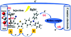
Since Grätzel's group presented fully operational dye-sensitized solar cells (DSSCs) in 1991,1 many experimental and theoretical methods have been applied for the understanding and improvement of DSSCs in order to boost high cell performance, involve environmentally benign materials and offer low fabrication cost devices for photovoltaic conversion.2–32 The DSSC devices are conceptually simple, consisting of essentially two electrodes and an electrolyte, where (at least) one of the electrodes is made light-sensitive allowing the conversion of light into electric energy. The function is thus not too different from that of a battery, however with the light-conversion ability as an added feature. Therefore, also the role of the sensitizing dye molecules and their interaction with the electrode/semiconducting material will be a central component to study. Until now, power conversion efficiencies (PCEs) over 14% have been achieved by using a combination of two co-sensitizing organic dyes.33,34 However, there still exists a wide space to develop the PCE of DSSCs. The charge-transport processes in DSSCs are critical for high performance of the DSSCs. In this aspect, the effects of the dynamical behaviour of the sensitized dye adsorbed onto the TiO2 surface is yet not fully understood.The central charge-transport processes (a–e) of DSSCs are outlined in Fig. 1. After the excitation of the dye molecule by sunlight in the visible to near-infrared (IR) range, which means that the electron of the dye is typically excited from its highest occupied molecular orbital (HOMO) to its lowest unoccupied molecular orbital (LUMO) (a), the excited electron will be transferred, into the conduction band of the semiconductor substrate (b), typically mesoporous TiO2. Some of the injected electrons will recombine with the oxidized dye or oxidized components of the electrolyte (c). The extent of this type of recombination loss will depend on the rate of electron injection within TiO2 with respect to that of charge recombination. Among different charge-transfer processes, the charge-recombination process is one of the most important limiting processes in DSSCs. As indicated above, the injected and energy-rich electrons will transport to the back contact and outer circuit through diffusion. Eventually, the redox couple in electrolyte will carry the electron from the counter electrode (d) to the oxidized dye for regeneration (reduction) of the dye (e). In summary, light energy is converted to electric energy generating a photocurrent.
Numerous studies35–47 on the charge transfer at the dye–TiO2 interface have been made, since the processes of charge-transfer dynamics48–50 and charge recombination significantly affect the PCE of DSSCs. In 1995, Grätzel and his co-workers reported a picosecond electron injection from the Ru-based dye used into the conduction band of TiO2.35 Similarly, Koops et al.43 presented a detailed comparison of interfacial electron-transfer kinetics in dye-sensitized solar cells containing the coumarin-based organic dye (NKX2677) with respect to those observed for the ruthenium-based organometallic dye, N719. The transient photoluminescence measurements indicated a <60 ps injection halftime for NKX2677 as compared to ∼350 ps injection halftimes for N719, and the recombination rate was found to be on the microsecond and millisecond time scale. The organic sensitizers showed faster recombination rates, which was probably caused by a generally closer localization of the dye's highest occupied molecular orbital (HOMO) to the semiconductor surface. Kopidakis et al. stated51 an electron-transport limited recombination with the redox electrolyte and indicated a causal link between electron transport and recombination by using photocurrent and photovoltage transient and spectroelectrochemical techniques. Listorti et al.44 reported a 100 ps electron injection rate from dyes to TiO2 and also a recombination rate on of microseconds and milliseconds. Several studies have also reported femtosecond injection kinetics for N719-sensitized TiO2.36–38 Ultrafast fluorescence dynamics demonstrated that the charge injection from the C343 dye to the conduction band of TiO2 occurred on the 200 fs time scale.36 Results from time-resolved laser techniques indicated an upper limit of 20 to 100 femtoseconds for the time needed to inject an electron from the dye into the semiconductor, which corresponded to the timescale for competing processes, such as charge redistribution.52
Recently, nanosecond transient absorption spectroscopy53 showed that the rates of electron injection from the sensitized dye to the semiconductor TiO2, and charge recombination from TiO2 to the sensitized dye were >(10 ns)−1 and (6.7–8.3 ns)−1, respectively. Moreover, different experimental techniques gave different rates of electron injection. Using a two-component exponential model, the rates of (450 fs)−1 weighted at 47% and (32 ps)−1 weighted at 53% of the spectral response from an IR light probe were obtained, whereas a rate of (250 fs)−1 from a transient ultraviolet-visible (UV-vis) probe, as well as a charge-recombination rate of the magnitude (2–920 ps)−1. Fang et al.54 determined the adsorption of dye molecules on nanoparticle surfaces through second-harmonic light scattering techniques and electron injection through ultrafast transient mid-infrared absorption. They suggested that aprotic solvents with high polarity (such as acetonitrile) yielded more efficient solar cell devices. In addition, injection of photoexcited electrons from the para-ethyl red dye to TiO2 nanoparticles was characterized by transient absorption on ultrafast time scales.55 The electron injection lifetimes were in the range of 250–300 fs in different solvent environment, but displayed a trend in correlation with solvent polarity (the higher polarity, the faster electron injection): the electron injection lifetime was the shortest (257 fs) in acetonitrile followed by dichloromethane (271 fs) and chloroform (296 fs).
Theoretical investigations have rarely been used to report the rate constants of electron injection from dyes to TiO2. Ronca et al.56 reported a joint theoretical and experimental investigation on the effect of TiO2 protonation on the interfacial electronic coupling and injection rate constants in organic dye-sensitized solar cells. Based on a simplified computational strategy of the organic sensitizer LUMO partial density of states (PDOS), they estimated the electron injection time about 3 and 6 fs. A density-functional theory approach (DFT) and time-dependent density-functional theory (TD-DFT) calculations were performed to study the solvent effects on the interfacial charge transfer in DSSC in three different solvents, including water, acetonitrile and carbon tetrachloride.57 The results suggested that acetonitrile was the best solvent for using in combination with an MZ-341 dye due to the electron and thermodynamic properties. Samanta et al.27 used DFT calculations to investigate the mechanism of electron injection and recombination at the dye–TiO2 interface, as well as the related structural properties. They estimated the rate constants of electron injection and charge recombination to be in the order of (10 ps)−1–(10 ns)−1 and (10 ps)−1–(100 ns)−1, respectively; thus highly competitive. Nevertheless, the use of a static structural model risks to overlook the effects of the intricate dynamical structural changes affecting the rate of charge transfer at the dye–TiO2 interface. Using experimental approaches to study the correlation between the dynamics of structure and charge transfer is extremely difficult in terms of the limited available techniques. However, a dynamical theoretical approach can offer valuable insights.
The main ambition of this work is to elucidate the effects of structural dynamics on the central processes of charge transfer at the dye–TiO2 interface. Ab initio molecular dynamics (aiMD) have been used to monitor the structural dynamics of protonated and deprotonated dyes in the L1–(TiO2)9, D35–(TiO2)9 and LEG4–(TiO2)9 model systems using the TeraChem code.58 The structural dynamics obtained were subsequently used to estimate the electronic coupling of electron injection, hole transfer and charge recombination by using the Amsterdam Density Functional-2019 (ADF) software.59 Using the Marcus–Hush theory,60,61 electronic coupling and re-organization energies can be used to estimate the rate constant of charge transfer of these central processes in the DSSCs. It should be noted here that the present models for dye–TiO2 interaction presumes that the main interactions take place between the dye–carboxylate group and the TiO2 slab. This implicitly also assumes the dye molecules to be organized in a well-ordered, self-assembled monolayer, even though experimental evidence indicates that the interaction most likely is significantly more complex.62–64 The detailed analyses include the following section (1) The electronic coupling and rate constants of electron transfer, hole transfer and charge recombination of a dynamical process. (2) The relationship between electronic coupling and structural properties including specific atom–atom distances, angles and dihedral angles. (3) For comparison, also the electronic coupling, rate constants and structural properties of the optimized systems of the protonated and deprotonated L1–TiO2, D35–TiO2 and LEG4–TiO2 systems have been estimated and are compared to the results obtained taking the structural dynamics into account.
Computational details
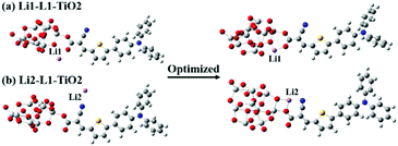
The model systems used in the current study are constructed from the D–π–A-type dye molecules L1, D35 and LEG4, as well as their deprotonated versions combined with a model of the TiO2 substrate, (TiO2)9, which has been validated to be sufficiently large to study the electron injection mechanism65 and has previously successfully been used to model the charge-transfer characteristic of DSSCs by Samanta et al.27and Li et al.,66 see Fig. 2. The initial structures were structurally optimized using Gaussian 16, Revision C.01.67 All dyes include the building blocks triphenylamine (TPA), thiophene and cyanoacrylic acid, which are typically denoted as the donor (D), π bridge and acceptor (A) parts, respectively. This paper aims to unveil the rate constant differences of charge transfer including the electron transfer from the LUMO of the dye to the LUMO of TiO2, the hole transfer from the HOMO of TiO2 to the HOMO of the dye, and the electron recombination reaction from the LUMO of TiO2 to the HOMO of the dye. The computational strategy can be outlined as follows.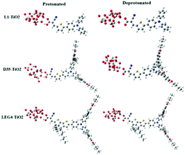 | ||
| Fig. 2 The molecular structures of protonated and deprotonated systems L1–TiO2, D35–TiO2 and LEG4–TiO2. | ||
Firstly, the initial molecular conformations were obtained from geometric optimization employing the B3LYP hybrid functional and basis sets of 6-31g(d) quality for all atoms, except for the Ti atoms. The LANL2DZ basis set including an effective-core potential (ECP) was used for the Ti atoms. In the next step, ab initio molecular dynamics (aiMD) was implemented using the TeraChem code, also at B3LYP level and with the same basis sets as in the initial calculations. Six simulation systems were constructed consisting of protonated-L1(TiO2)9, protonated-D35(TiO2)9, protonated-LEG4(TiO2)9, deprotonated-L1(TiO2)9, deprotonated-D35(TiO2)9 and deprotonated-LEG4(TiO)9. The total simulation time for all systems was 100 ps and the time step 1 fs. The canonical ensemble NVT was utilized. A Langevin thermostat was adopted to retain the simulation temperature at 300 K.
After the aiMD simulations, snapshots of the first 50 ps were selected for subsequent estimation of the charge-transfer rate constants at every 0.1 ps interval. In order to detect any faster correlations, all simulations were also analyzed every fs in a 0.5 ps section in the steady-state region of the simulations. No additional information could be extracted from these regions of higher temporal resolution. Following the Marcus–Hush theory, the electronic coupling and re-organization energy are essential for estimating the rate constants of charge transfer. As a popular computational chemistry software package, ADF has been successfully used to quantitatively predict the charge mobilities of π-stacked systems,59 the charge transport in columnar stacked triphenylenes,68 and absolute rate of hole transfer in DNA.69 In this context, ADF was used to obtain the electronic coupling using the PW91 density functional at the generalized-gradient approximation level and basis sets of TZ2P quality.70 In the electronic coupling calculations, the systems consisting of a dye and the TiO2 model were separated into two fragments: the dye molecule and the TiO2 model, respectively. Calculations on the separated fragments with full symmetry was carried out to generate the matrix elements of the molecular Kohn–Sham Hamiltonian in terms of fragment orbitals. In the charge-integral approach, a tight-binding approximation is employed, which treats the electron or the hole as a single orbital and assumes that only the nearest neighbouring fragments are involved in the coupling. Subsequently, the charge-transfer integrals and spatial overlap integrals of the HOMOs and LUMOs of the dyes and TiO2, respectively, were calculated. This offers an estimation of the electronic coupling of electron transfer, hole transfer and charge recombination, modelled by the coupling between the LUMO of the dye and the LUMO of the TiO2 fragment, the HOMO of the dye and the HOMO of the TiO2 fragment, and finally the HOMO of the dye and the LUMO of the TiO2 fragment, respectively. To study the solvent effect, the electronic coupling calculations of both with and without considering implicit acetonitrile effect have been done for deprotonated L1–TiO2 system. The scalar level in the ZORA formalism and the MAPA potential were used for including relativistic effects. Dispersion correction using the grimme4 model with s6 = 1.0 s8 = 0.7728 a1 = 0.3958 a2 = 4.9341 were used. The input files used for the calculations of electronic coupling can be found in ESI.† In order to obtain an accurate re-organization energy to be used in the estimates of charge-transfer rate constants, two different methods were used including optimized structures, as well as a statistical method. Both Gaussian 16 and ADF were used to calculate the re-organization energies of the optimized models to assure that realistic energies were obtained. The statistical re-organization energies of both optimization and aiMD simulation methods yielded by the Nelsen four-point method were carried out and the values obtained from aiMD simulations were ultimately adopted to estimate the rate constant of charge transfer.
Results and discussion
1 Charge-transfer analysis
Light absorption in a DSSC device results in the excitation of an electron in the sensitizing dye used. In semiconductor-type of solar cells, this would have been described in terms of an exciton being formed. However, in a molecular device, such as a DSSC, the function can be focused on the excited electron, regarding the hole formed in the dye HOMO as stationary. Since modern dyes used in DSSCs are of push–pull type, charge separation is typically generated already upon electron excitation. In organic dyes, such as the ones studied in this work, the main first excitation is a singlet-to-singlet excitation mainly involving a transition from the HOMO to the LUMO of the dye. Injection to the TiO2 substrate typically takes place on the femtosecond scale, as reviewed above, providing that the dyes have been chosen properly and electrolyte additives not push the conduction band (LUMO) of the TiO2 substrate to too high energies. The dyes in this study have all been shown to work excellently as sensitizing dyes in DSSCs. Based on the Marcus–Hush formula,60,61 the electron transfer, hole transfer and charge recombination can all be evaluated using eqn (1), with the proper re-organization energies, changes in Gibbs free energy and couplings used as input. | (1) |
The formulas of optimization method27 for re-organization energies calculation are shown in eqn (2).
 | (2) |
 , ETiO2(−)−, ETiO2(+)+, ETiO2(0)−, ETiO2(0)+ and
  the same level of theory. The re-organization energies obtained from the aiMD simulations were ultimately used in this study.
 | (3) |
 represent the energies of the neutral dye and the neutral TiO2 model in their neutral state. E0dye(+) and E0dye(−) symbolize the energies of the neutral dye obtained from cationic and anionic snapshot structures, respectively. Edye(0)− and ETiO2(0)− express the energies of the anions of the dye molecule and the TiO2 substrate from their neutral structures. ETiO2(0)+ and ETiO2(+)+ symbolize the energies of the cations from neutral TiO2 snapshot structures and cationic snapshot structures, respectively.
  represent the energy of the neutral TiO2 model generated from the anionic structure snapshots.
A charge-transfer state should ideally be modelled by the optimized-excited state structure. However, because of severe convergence problems of excited-state structures for quite large systems, it is infeasible to obtain the optimized electronic structure and energy of the excited state. Cornil et al.75 obtained the Gibbs free energy difference by computing the energies of the isolated neutral and charged donor/acceptor systems (ED/EA and ED+/EA−), as well as the energy of the excited donor  and the energy of Coulombic interaction between the donor and the acceptor ΔEcoul. The Gibbs free energy difference of charge recombination (ΔGrec) and electron transfer (ΔGe) were analogously calculated by ED + EA − E+D − E−A + ΔEcoul and
  , respectively. This approximation is suitable if the main interaction term between the donor and the acceptor is the Coulombic one.
Liu et al.74 also reported an approach to evaluate the Gibbs free energy difference of the charge recombination (ΔGrec) and electron transfer (ΔGe). They suggested that the ΔGrec can be obtained from the energy difference between the sum of ED and EA, and the energy of the charge-separated state Ecs. ΔGe can be computed by the energy difference between the energy Ecs and the sum of the excited state donor energies  and EA. Liu and co-workers noted that the energy difference between the donor/acceptor dimer and the sum of the energy of the separate donor/acceptor typically is quite small (0.02 eV) because of the small Coulombic interaction energy. Therefore, it is reasonable to assume that the energy of the complex of the donor excited state and acceptor ground state properly can be represented by the sum of the separate molecular component in the excited state
  and the ground state EA generating only a small errors. However, the authors pointed out that the charge-separated state energy cannot simply be replaced by the sum of the separate entity charge energy, ED+ and EA−, because the interaction between the charged fragments, D+ and A−, is large.
Based on the above methods to estimate the Gibbs free energy difference, we employed the above computational strategy to obtain the Gibbs free energy difference for the protonated and the deprotonated L1–TiO2, D35–TiO2, LEG4–TiO2 systems. In conclusion, a vertical excited-state calculation of the dye–TiO2 system in the structure of the ground state is used as an approximation to acquire the energy of the charge-separated state Ecs. Furthermore, all the interaction energies between the dye and the TiO2 substrate before and after electron transfer, hole transfer and charge recombination were considered. The formula used to estimate the Gibbs free energy differences of electron transfer, hole transfer and charge recombination are shown in eqn (4). For the deprotonated L1–TiO2 system including implicit solvent effect, the energy of the charge-separated state Ecs could be obtained by geometric optimization of the excited state (feasible computational effort).
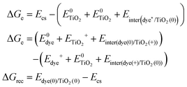 | (4) |
 is the energy of the vertical triplet excited state of the dye.
  and E0dye are the energies of the neutral TiO2 model and the dye, respectively. ETiO2+ and Edye+ represent the energies of the cationic TiO2 model and the dye, respectively. Einter(Dye(*)/TiO2(0)) represents the interaction energy between the excited-state dye and the neutral TiO2 model, which here is regarded to model the interaction between the ground-state dye and the ground-state TiO2 fragment. Einter(dye(0)/TiO2(+)) is the interaction energy between the neutral dye and the cationic TiO2. Finally, Einter(dye(+)/TiO2(0)) is the interaction energy between the cationic dye and the neutral TiO2 substrate. The interaction energies include BSSE corrections. The changes in Gibbs free energy of electron transfer, hole transfer and charge recombination for the protonated and the deprotonated L1–TiO2, D35–TiO2 and LEG4–TiO2 systems are listed in Table 3.
The electronic coupling of charge transfer reflects the strength of the orbital interaction between the selected dye and the TiO2 fragment orbitals and therefore gives information regarding the probability of charge transfer. The electronic coupling of electron transfer, hole transfer and charge recombination of the protonated and deprotonated L1–TiO2, D35–TiO2 and LEG4–TiO2 systems during a 50 ps aiMD simulation are depicted in Fig. 3(a–i) and 4(a–i), respectively. Fig. 3(a–c, d–f and g–i) show the electronic coupling of electron transfer, hole transfer and charge recombination for the protonated L1–TiO2, D35–TiO2 and LEG4–TiO2 systems, respectively. The electronic couplings of electron transfer, hole transfer and charge recombination vary significantly in the systems: 1.0 × 10⁻⁵–0.139, 1.0 × 10⁻⁵–0.012 and 1.0 × 10⁻⁵–0.168 eV for the protonated L1–TiO2 system; 0.003–0.347, 1.0 × 10⁻⁵–0.004 and 1.3 × 10⁻⁴–0.192 eV for the protonated D35–TiO2 system; and 1.0 × 10⁻⁵–0.194, 1.0 × 10⁻⁵–0.016 and 1.8 × 10⁻⁴–0.126 eV for the protonated LEG4–TiO2 system, respectively. The average electronic coupling of electron transfer, hole transfer and charge recombination are 0.056, 0.002 and 0.045 eV for the protonated L1–TiO2 system; 0.179, 0.001 and 0.095 eV for the protonated D35–TiO2 system, and 0.069, 0.002 and 0.040 eV for the protonated LEG4–TiO2 system, respectively. The electronic coupling of hole transfer for all the three systems are extremely low, which suggests the interaction between the HOMOs of protonated L1, D35 and LEG4 and the HOMO of the TiO2 model are quite weak. The shapes and the number of the peaks of electronic coupling of electron transfer and charge recombination are extraordinary similar, while the electronic couplings of charge recombination are about half that of the electron transfer. This indicates that there exists some kind of relationship between electron transfer and charge recombination, which is consistent with the results reported by Kopidakis et al.51
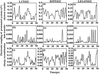 | ||
| Fig. 3 (a–i) The electronic coupling of electron transfer, hole transfer and charge recombination for the protonated L1–TiO2, D35–TiO2 and LEG4–TiO2 systems. | ||
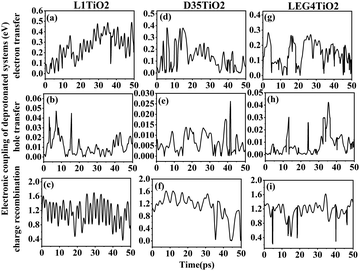 | ||
| Fig. 4 (a–i) The electronic coupling of electron transfer, hole transfer and charge recombination for the deprotonated L1–TiO2, D35–TiO2 and LEG4–TiO2 systems. | ||
As noted above, the deprotonated dye systems described below will represent models closest to the systems studied experimentally. The electronic coupling of electron transfer, hole transfer and charge recombination vary from 7.2 × 10⁻⁴–0.381, 5.0 × 10⁻⁵–0.047 and 0.369–1.695 eV for the deprotonated L1–TiO2 system, 2.5 × 10⁻⁴–0.381, 1.0 × 10⁻⁵–0.026 and 0.001–1.569 eV for the deprotonated D35–TiO2 system, and 4.6 × 10⁻⁴–0.282, 1.0 × 10⁻⁵–0.042 and 0.389–0.619 eV for the deprotonated LEG4–TiO2 system, respectively. The average electronic coupling of electron transfer, hole transfer and charge recombination are 0.255, 0.011 and 1.135 eV for the deprotonated L1–TiO2 system; 0.131, 0.007 and 1.100 eV for the deprotonated D35–TiO2 system; and 0.146, 0.008 and 1.154 eV for the deprotonated LEG4–TiO2 system, respectively. The electronic coupling of electron transfer of deprotonated L1–TiO2, D35–TiO2 and LEG4–TiO2 systems are all of same order of magnitude and slightly larger than those of the protonated systems. This suggests that the electron transfer of the deprotonated systems show slightly higher probability. Electronic coupling of hole transfer for all the three deprotonated systems are apparently lower than those of electron transfer by about one order of magnitude, which suggests that the interaction between the LUMOs of the deprotonated L1, D35 and LEG4 dyes and the LUMO of TiO2 are stronger than those between the HOMO of the deprotonated L1, D35 and LEG4 dyes and the HOMO of TiO2. To our surprise, the electronic coupling of charge recombination in the deprotonated L1–TiO2, D35–TiO2 and LEG4–TiO2 systems are significantly higher than those of electron transfer and hole transfer, as well as higher than the corresponding coupling in the protonated systems. The shapes and the number of peaks of the electronic coupling dynamics of electron transfer and charge recombination are quite similar, also compared to those of the protonated systems. The electronic coupling of electron transfer seems to be correlated with charge recombination, which again is in good agreement with the results reported by Kopidakis et al.51
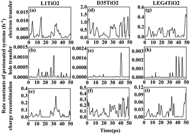 | ||
| Fig. 5 (a–i) The rate constants of electron transfer, hole transfer and charge recombination for the protonated L1–TiO2, D35–TiO2 and LEG4–TiO2 systems. | ||
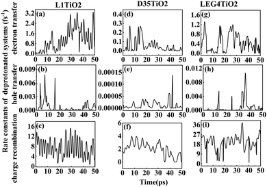 | ||
| Fig. 6 (a–i) The rate constants of electron transfer, hole transfer and charge recombination for the deprotonated L1–TiO2, D35–TiO2 and LEG4–TiO2 systems. | ||
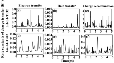
Fig. 6(a–i) shows the rate constants of charge transfer for the deprotonated L1–TiO2, D35–TiO2 and LEG4–TiO2 systems. The fastest rate constants of electron transfer, hole transfer and charge recombination are (0.3 fs)−1, (127.5 fs)−1 and (0.007 fs)−1 for deprotonated L1–TiO2 system; (1.4 fs)−1, (7.3 ps)−1 and (0.3 fs)−1 for deprotonated D35–TiO2 system; and (0.8 fs)−1, (93.6 fs)−1 and (0.03 fs)−1 for deprotonated LEG4–TiO2 system. The corresponding average value of electron transfer, hole transfer and charge recombination are (0.9 fs)−1, (1.4 ps)−1 and (0.1 fs)−1 for deprotonated L1–TiO2 system; (19.7 fs)−1, (79.6 ps)−1 and (0.5 fs)−1 for deprotonated D35–TiO2 system; and (2.3 fs)−1, (1.2 ps)−1 and (0.05 fs)−1 for deprotonated LEG4–TiO2 system. In contrast to the corresponding protonated systems, the rate constants of charge recombination of the deprotonated systems are about two or three order of magnitude faster. These results demonstrate that when an electron is transferred from a deprotonated dye to TiO2 there is a high probability (risk) that it will transfer back to the dye increasing losses of injected, energy-rich electrons from the TiO2 substrate. In this context, it is notable that DSSCs based on liquid electrolytes normally include electrolyte additives in terms of salts of small, polarizable cations, such as Li+ or Mg2+. The polarizing cations are thought to assemble at the dye–TiO2 interface, where they can both affect the charge-transfer balance and the energy levels of both the adsorbed dyes and the TiO2 substrate. It can be anticipated that added Li+ ions to the electrolyte may have a similar effect as the protons of the cyanoacrylic acid groups of the dyes in retarding recombination loss rates. This will be investigated in the following section.
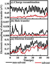
1.6.1 Solvent effects on electronic couplings of charge transfer. The electronic couplings of charge transfer reflect the strength of the frontier molecular orbital interaction between the donor L1 and the acceptor TiO2, and therefore provide information regarding the probability of charge transfer. The electronic couplings of electron transfer, hole transfer and charge recombination of the deprotonated L1–TiO2 model are outlined in Fig. 9(a–c) for both solvent and non-solvent conditions, which are represented by black and red curves, respectively. The electronic couplings of electron and hole hopping in acetonitrile are slightly smaller than those in gas phase. The electronic couplings of electron transfer for non-solvent and solvent conditions range from 0.0018–0.4880 and 0.0015–0.2975 eV, respectively, and the corresponding average values are 0.2515 and 0.1372 eV. The electronic couplings of hole transfer for non-solvent and solvent systems range from 10−5–0.0301 and 10−5–0.0058 eV, respectively, and the corresponding average values are 0.0107 and 0.0015 eV. However, the electronic couplings of charge recombination in acetonitrile presents dramatic decrease as compared with those in gas phase. The electronic couplings for non-solvent- and solvent-containing systems range from 0.4736–1.6985 and 0.0011–0.3895 eV, respectively. The corresponding average values are 1.152 and 0.1110 eV, respectively. The electronic couplings of charge recombination in non-solvent conditions are 10 times higher than those in solvent condition. This suggests that the presence of a reasonably dielectric solvent, such as acetonitrile, significantly can reduce charge recombination from TiO2 to deprotonated L1.
1.6.2 Solvent effects on the rate of charge transfer reactions. A higher DSSC PCE can be achieved by combining an ultrafast electron injection and a much slower charge-recombination process. Some papers report that acetonitrile is the best solvent for promoting the PCE of DSSCs.55,57 Thus, it is of special interest to investigate how the rate constant of charge transfer is affected by the presence of acetonitrile. The dynamics rate constants of electron transfer and charge recombination in the gas phase and implicit acetonitrile of the deprotonated L1–TiO2 model system are exhibited in Fig. 10(a–d). The ranges and averages of the rate constants are listed in Table 4. In gas phase, the rate constants of electron transfer and charge recombination for the deprotonated L1–TiO2 model system are ranging from (0.1 ns)−1 –(0.3 fs)−1 and (1.4 fs)−1–(0.07 fs)−1, respectively. Inclusion of acetonitrile implicitly using the PCM model gives the rate constants of electron transfer and charge recombination for the deprotonated L1–TiO2 model system ranging from (32.4 fs)−1–(0.8 fs)−1 and (30.3 ns)−1–(1.3 fs)−1, respectively.
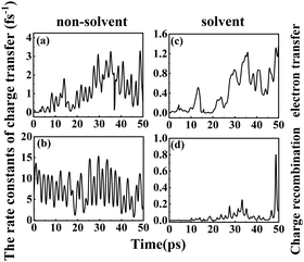 | ||
| Fig. 10 (a–d) The rate constants of electron transfer and charge recombination of the deprotonated L1–TiO2 model system: without solvent effect (left), with solvent effect (right). | ||
The average of the rate constants of electron transfer and charge recombination in gas phase are (0.9 fs)−1, and (0.1 fs)−1 respectively. While the average of the rate constants of electron transfer and charge recombination for the deprotonated L1–TiO2 model system range from (2.4 fs)−1 and (21.9 fs)−1, respectively in acetonitrile. From the above data, we can deduce that the rate constants of electron transfer are in the femtosecond time scale, irrespective if the system is in acetonitrile or in gas phase. The rate constants of charge recombination in gas phase are still in the femtosecond time scale. However, the rate constants of charge recombination are approximately two orders of magnitude lower in acetonitrile than in gas phase, which suggests that the solvent acetonitrile plays an important role in retarding the charge recombination loss rates. This indicates that a solvent such as acetonitrile promotes higher PCEs of DSSCs, which is in accord with the results of Fang et al.54,55
2 Analysis of the correlation between dye configuration and electronic coupling
The current dynamical study also allows a study of the correlation between specific dye configurations and the rate constants of charge-transfer obtained. Fig. 11 shows the analyzed structures. The effects specifically studied involve hydrogen bonding between one oxygen atom of TiO2 and the O–H of the cyanoacrylic acid group of the dyes, the Ti–O bond lengths, the O–O distances, the O–Ti–O angle distributions and C–O–Ti–O dihedral angles, Φ S–C–C–C and Ψ C–C–C–C. The structural analyses for the aiMD simulation using 1.0 fs time steps are given in the ESI.† If the relation between structural properties and electronic coupling/transfer rate constant is qualitative, we will not be able to identify a cause-effect correlation between the snapshot structures and the electronic coupling from the correlation with a resolution of 0.1 ps in the aiMD simulation. In addition, the aiMD simulation of the protonated L1–TiO2 system was also evaluated in a 0.5 ps steady-state region and 100 snapshots were extracted to render a higher time resolution for comparison, as shown in Fig. S11(a–c) and S12(a–g) (ESI†). The correlation between dye conformation and electronic coupling/charge-transfer rate constants were explored for 20 continuous snapshots, listed in Table S4 (ESI†). However, we cannot identify any clear correlation. Consequently, there are no simple structural-rate constant correlation to be extracted from the dynamical results. Instead, the high/low rate constants of charge transfer detected seem to result from complex concerted structures of the dyes studied. We had expected to note a correlation with the dye–TiO2 distance, but taking the full dye structure dynamics into account any such correlation downs in the structural overall effects. For this reason, the correlations linked to the dye–TiO2 distance is studied explicitly below.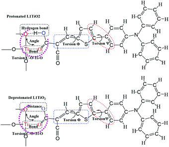 | ||
| Fig. 11 The schematics of the analyzed molecular structures for correlation with the detected charge-transfer dynamics. | ||
3 Scanning of Ti–O(dye) distance and charge-transfer rates
In order to study the effect of the Ti–O(dye) distance on the electronic coupling and rate constant of charge transfer, a fixed scan of Ti–O(dye) distance from 1.67 to 3.67 Å for the deprotonated L1–TiO2 system was performed. The corresponding electronic coupling and rate constant of charge transfer are depicted in Fig. 12(a–f). The electronic coupling and rate constants of electron transfer, hole transfer and charge recombination present a steep decrease with increasing Ti–O(dye) distance from 1.67 to 2.47 Å. For Ti–O(dye) distances longer than 2.50 Å, the curves of the electronic coupling and rate constant of charge transfer flatten out. This suggests, as expected that when the Ti–O(dye) distance increases, the frontier orbital interactions get weaker. Thus, the corresponding electronic coupling of charge transfer gets weaker and the corresponding rate constants of charge transfer decrease. An exponential relation is found for the relationship between Ti–O(dye) distance and electronic coupling or rate constants of electron transfer and charge recombination. This indicated that straightforward orbital overlap may be involved. There also exists an exponential relation between Ti–O distance from 1.67 to 2.27 Å and the electronic coupling/rate constant of hole transfer. However, when the Ti–O distance is longer than 2.30 Å, the curves of electronic coupling and rate constant of hole transfer reach the plateau region, which suggests that the overlap of the HOMO of deprotonated L1 and LUMO of the TiO2 are very small. All the relations are shown in Fig. S13(a–f) (ESI†). The current results are in contrast to the results in the preceding section, where it seems that full structural flexibility will dominate both changes in energetics as well as in simple correlations.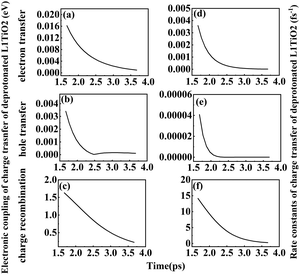 | ||
| Fig. 12 (a–f) Electronic coupling and rate constant of electron transfer, hole transfer and charge recombination for deprotonated L1–TiO2 system with Ti–O(dye) distances ranging from 1.67–3.67 Å. | ||
4 Statically optimized structures and charge-transfer rates
For sake of comparison, an analysis of the electronic coupling and charge-transfer rate constants were also performed for systems statically optimized in the protonated and deprotonated L1–TiO2, D35–TiO2 and LEG4–TiO2 systems, as listed in Table 5. All electronic couplings are in the range of the corresponding electronic coupling as obtained from the aiMD simulation snapshots. Most of the rate constants of electron transfer and charge recombination are on femtosecond time scale and few of them are on picosecond and nanosecond time scale, which all are within the range of the rates of electron transfer and charge recombination yielded by aiMD snapshots. Moreover, the rate constant of electron transfer of the protonated D35–TiO2 system is higher than those of the protonated L1–TiO2 and LEG4–TiO2 systems, which is consistent with those obtained from the aiMD simulations. The above analysis illustrates that the optimized systems may result in an arbitrary value of electronic coupling and rate constant of charge transfer when compared to the snapshots generated from aiMD simulations. It is difficult to identify the arguments for why the geometrically optimized structures should provide unique and reliable results.| ec | L1–TiO2 | D35–TiO2 | LEG4–TiO2 | |||
|---|---|---|---|---|---|---|
| p | dep | p | dep | p | dep | |
| a Stand for electronic coupling. b Stand for rate constant of charge transfer. c Represent electron transfer. d Represent hole transfer. e Represent charge recombination. | ||||||
| et | 0.0103 | 0.0339 | 0.2768 | 0.1456 | 0.0028 | 0.0925 |
| ht | 0.0004 | 0.0001 | 0.0003 | 0.0034 | 0.0003 | 0.0007 |
| cr | 0.0109 | 1.4260 | 0.1370 | 1.0185 | 0.0001 | 1.4405 |
| Rate constants | ||||||
| et | 1.9 ps | 51.4 fs | 6.4 fs | 4.1 fs | 7.4 ps | 7.5 fs |
| ht | 380.4 ps | 100 ns | 775.8 ps | 615.4 ps | 698.3 ps | 341.9 ps |
| cr | 0.5 ps | 0.1 fs | 4.2 fs | 1.3 fs | 11.4 ns | 0.2 fs |
Conclusions
The current study has employed aiMD simulations for the study of the interaction between three organic dyes, L1, D35 and LEG4, with a model of a TiO2 semiconductor substrate. Instead of a static approach, where the systems are geometrically optimized followed by an analysis of electronic coupling, the systems have been dynamically traced and structural snapshots have been extracted for the subsequent analysis of electronic coupling and rate constants of charge transfer. This dynamic approach has allowed us to identify several previously unknown features.Generally, the structural dynamics of a dye adsorbed/anchored to a TiO2 surface significantly affects the orbital overlap and all resulting properties in the systems. More specifically, electron coupling and rate constants of charge transfer for central processes in DSSC devices cover a huge range. The most relevant data to compare with experiment will be averages sampled over a relevantly large time of simulation. A comparison with a static evaluation of the same parameters indicate that the values obtained from such an analysis risk to be arbitrarily placed in the window of rate constants defined by a dynamic approach. Our results indicate that a proper analysis of electronic coupling and rate constants of transfer need to invoke the structural dynamics in order to offer statistical results that can be compared with experiment, where the results by necessity represent averages over time and space.
More specifically, the results of the dynamic analysis of electronic coupling and rate constants of charge transfer also offer some new and unexpected insights. First, recombination loss rate constants of deprotonated dyes attached to the TiO2 model are one or two order of magnitude higher than those of electron injection. This shows that high photocurrents will need to rely on fast transport rates away from the dye interface in the TiO2 substrate. Second, it is clear that this potential problem at least partly can be mitigated by salts of polarizing cations added to the electrolyte. Finally, a dielectric solvent, such as acetonitrile, can favour higher PCEs of DSSCs by retarding recombination loss rate constants. All the charge-transfer processes studied are quite fast and in accordance with experiment.
There is no simple correlation identified between high or low transfer rate constants and specific structural arrangements in terms of atom–atom distances, angles or dihedral arrangements of the dye sub-units. However, a scan of the Ti–O(dye) distance alone suggests that an exponential relation exists between the Ti–O(dye) distance and the electronic coupling/rate constants of charge transfer, which suggests that the Ti–O(dye) distance does play a significant role for the electronic coupling between the dye and the substrate, although its overall effect drowns in the concerted structural dynamics of the system as a whole.
Conflicts of interest
There are no conflicts to declare.Acknowledgements
The Swedish Research Council and Stiftelsen Ole Eriksson Byggmästare are gratefully acknowledged for their financial support. We thank the National Supercomputer Centre at Linköping University for computation resources. Dr Timofei Privalov is acknowledged for valuable discussions at the initial stages of the project.Notes and references
- O. R. Brian and M. Grätzel, A low-cost high-efficiency solar cell based on dye-sensitized colloidal TiO2 films, Nature, 1991, 353, 737–740 CrossRef.
- J. N. Clifford, E. Palomares, M. K. Nazeeruddin, M. Gratzel, J. Nelson, X. Li, J. L. Nicholas and J. R. Durrant, Molecular control of recombination dynamics in dye-sensitized nanocrystalline TiO2 films: Free energy vs. distance dependence, J. Am. Chem. Soc., 2004, 126, 5225–5233 CrossRef CAS PubMed.
- M. Grätzel, Solar energy conversion by dye-sensitized photovoltaic cells, Inorg. Chem., 2005, 44, 6841 CrossRef PubMed.
- S. A. Haque, E. Palomares, B. M. Cho, A. N. M. Green, N. Hirata, D. R. Klug and J. R. Durrant, Charge separation versus recombination in dye-sensitized nanocrystalline solar cells: The minimization of kinetic redundancy, J. Am. Chem. Soc., 2005, 127, 3456–3462 CrossRef CAS PubMed.
- K. Daibin, I. Seigo, W. Bernard, K. Cedric, E. M. Jacques, H. B. Robin, M. Z. Shaik and M. Grätzel, High molar extinction coefficient heteroleptic ruthenium complexes for thin film dye-sensitized solar cells, J. Am. Chem. Soc., 2006, 128, 4146–4154 CrossRef PubMed.
- F. De Angelis, S. Fantacci, A. Selloni, M. K. Nazeeruddin and M. Grätzel, Time-dependent density functional theory investigations on the excited states of Ru(II)–dye-sensitized TiO2 nanoparticles: The role of sensitizer protonation, J. Am. Chem. Soc., 2007, 129, 14156–14157 CrossRef CAS PubMed.
- H. Anders, B. Gerrit, S. Licheng, K. Lars and P. Henrik, Dye-sensitized solar cells, Chem. Rev., 2010, 110, 6595–6663 CrossRef PubMed.
- T. Chao, Y. Xichuan, Y. Chao, L. Shifeng, C. Ming, H. Anders and S. Licheng, Molecular design of anthracene-bridged metal-free organic dyes for efficient dye-sensitized solar cells, J. Phys. Chem. C, 2010, 114, 9101–9110 Search PubMed.
- M. Antonio, A. Xavier, B. Marc and C. G. Philippe, Theoretical study of new ruthenium-based dyes for dye-sensitized solar cells, J. Phys. Chem. A, 2011, 115, 3596–3603 CrossRef PubMed.
- T. Priti, D. Pablo, B. J. Michael, J. S. Henry and M. H. Laura, Electron mobility and injection dynamics in mesoporous ZnO, SnO2, and TiO2 films used in dye-sensitized solar cells, ACS Nano, 2011, 5, 5158–5166 CrossRef PubMed.
- S. Qu and H. Tian, Diketopyrrolopyrrole (DPP)-based materials for organic photovoltaics, Chem. Commun., 2012, 48, 3039–3051 RSC.
- M. Liang and J. Chen, Arylamine organic dyes for dye-sensitized solar cells, Chem. Soc. Rev., 2013, 42, 3453–3488 RSC.
- M. Lemin, W. Yaxu, J. Jiamin, G. Xugeng, H. Panpan, W. Li and Z. Jinglai, Rational design of phenothiazine-based organic dyes for dye-sensitized solar cells: The influence of π-spacers and intermolecular aggregation on their photovoltaic performances, J. Phys. Chem. C, 2020, 124, 9233–9242 CrossRef.
- W. Yue, K. Hiroto, I. Masatoshi, G. Sabapathi, M. Shigeki, M. Tomotaka, M. Atsuya, U. Masanobu, Y. Yuhsuke, F. Susumu, N. Yusuke, Y. Yoshihisa, H. Mamiko, Y. Michito, K. Gakhyun, K. Dongho and F. Hiroyuki, Synthesis of a black dye with absorption capabilities across the visible-to-near-infrared region: A Mo-mixing approach via heterometal coordination of expanded porphyrinoid, J. Am. Chem. Soc., 2020, 142, 6807–6813 CrossRef PubMed.
- H. Tomohiro, I. Hitomi, N. Shimpei, K. Yuma and I. Hiroshi, Effect of ligand structures of copper redox shuttles on photovoltaic performance of dye-sensitized solar cells, Inorg. Chem., 2020, 59, 452–459 CrossRef PubMed.
- S. L. R. Chathuranga, N. G. Jacqueline, L. D. Austin, A. A. Shane, M. William, I. H. Nathan, H. D. Jared and N. S. Colleen, Donor–acceptor–donor NIR II emissive rhodindolizine dye synthesized by C–H bond functionalization, J. Org. Chem., 2019, 84, 13186–13193 CrossRef PubMed.
- M. E. Ahmed and Z. Burkhard, Electron dynamics in dye-sensitized solar cells influenced by dye–electrolyte complexation, J. Phys. Chem. C, 2020, 124, 16300–16307 CrossRef.
- B. M. B. Youssef, R. Timothy, S. Jeremy, B. Sebastien, V. Florence, I. Guillaume, S. Raphaël, F. Jennifer, K. Matthieu, C.-K. Murielle, A. Vincent and P. Anna, Dye-sensitized photocathodes: Boosting photoelectrochemical performances with polyoxometalate electron transfer mediators, ACS Appl. Energy Mater., 2020, 3, 163–169 CrossRef.
- J. K. Yong, C. Hyeongdo, S. K. Choong, L. Gyusoup, P. Jiwon, E. P. Seong and J. C. Byung, Dye-sensitized solar cell–thermoelectric hybrid generator utilizing bipolar conduction in a unified element, ACS Appl. Energy Mater., 2020, 3, 4155–4161 CrossRef.
- S. Yasemin, S. Marko, K. Huiseon, T. Joel, S. Rosario, F. Marina, M. Z. Shaik, E. M. Jacques, G. T. Michael and H. Anders, Liquid state and zombie dye sensitized solar cells with copper bipyridine complexes functionalized with alkoxy groups, J. Phys. Chem. C, 2020, 124, 7071–7081 Search PubMed.
- E. Yamuna, L. Fangsian, F. Miaosyuan, P. Kumaresan, N. Jenshyang, W. Yiching, L. Genehsiang, C. Mingchou and H. Kuochuan, Thioalkyl-functionalized bithiophene (SBT)-based organic sensitizers for high-performance dye-sensitized solar cells, ACS Appl. Mater. Interfaces, 2020, 12, 15071–15079 CrossRef PubMed.
- L. Wenwu, J. Wei, L. Yucheng, N. Wenjun, L. Maocheng, Z. Kun, Z. Luyin, L. Ling, K. Lingbin and C. Yulun, Platinum-free ternary metallic selenides as nanostructured counter electrode for high-efficiency dye-sensitized solar cell by interface engineering, ACS Appl. Energy Mater., 2020, 3, 3704–3713 CrossRef.
- Z. Weiyi, W. Li, M. Lemin, J. Jiamin, R. Hehe, H. Panpan, Å. Hans and Z. Jinglai, Computational protocol for precise prediction of dye-sensitized solar cell performance, J. Phys. Chem. C, 2020, 124, 3980–3987 CrossRef.
- S. Vediappan, K. S. Anup and K. C. Mrinmoy, Nanoporous reduced graphene oxide and polymer composites as efficient counter electrodes in dye-sensitized solar cells, ACS Appl. Electron. Mater., 2020, 2, 626–634 CrossRef.
- Z. Quande, W. Shuxian, Z. Sainan, W. Xiaofei, X. Zhijie, W. Zhaojie, W. Baojun and L. Xiaoqing, Theoretical investigation on copper(I) complexes featuring a phosphonic acid anchor with asymmetric ligands for DSSC, ACS Appl. Electron. Mater., 2020, 2, 2141–2150 CrossRef.
- X. Peng, Z. Cai-Rong, W. You-Zhi, Y. Li-Hua, C. Yu-Hong, L. Zi-Jiang and C. Hong-Shan, Fusing thienyl with N-annulated perylene dyes and photovoltaic parameters for dye-sensitized solar cells, J. Phys. Chem. A, 2020, 124, 3626–3635 CrossRef PubMed.
- N. S. Pabitra, D. Majumdar, R. Szczepan and L. Jerzy, First-principles approach for assessing cold electron injection efficiency of dye-sensitized solar cell: Elucidation of mechanism of charge injection and recombination, J. Phys. Chem. C, 2020, 124, 2817–2836 CrossRef.
- M. Mahyar, S. S. Gurpreet, M. W. Zhiming, S. Barry, Z. Haiguang and R. Federico, Role of carbon nanotubes to enhance the long-term stability of dye-sensitized solar cells, ACS Photon., 2020, 7, 653–664 CrossRef.
- D. Ke, M. C. Jacqueline, L. R. Jonathan, N. Christopher, C. Hao, Y.-G. Angel, W. E. Jeffrey and B. G. S. Gavin, Dye nanoaggregate structures in Mk-2, N3, and N749 dye⋯TiO2 interfaces that represent dye-sensitized solar cell working electrodes, ACS Appl. Energy Mater., 2020, 3, 900–914 CrossRef.
- O. WonChun and A. Yonrapach, A new aspect for band gap energy of graphene-Mg2CuSnCOO6-gallic acid as a counter electrode for enhancing dye-sensitized solar cell performance, ACS Appl. Mater. Interfaces, 2019, 11, 38859–38867 CrossRef PubMed.
- F. Z. Holly, R. E. William, B. Abdelaziz, K. H. Olivia, A. W. Joseph, A. P. Alexander, B. G. David and B. Rizia, Improving light harvesting in dye-sensitized solar cells using hybrid bimetallic nanostructures, ACS Photon., 2016, 3, 385–394 CrossRef.
- M. Valentin, D. Hakan, C. Elsa, J. Bruno and G. Thomas, Role of electronic relaxation in the injection process of organic push–pull dyes in complete dye-sensitized solar cells, J. Phys. Chem. Lett., 2019, 10, 5076–5081 CrossRef PubMed.
- Y. K. Eom, S. H. Kang, I. T. Choi, Y. Yoo, J. Kim and H. K. Kim, Significant light absorption enhancement by a single heterocyclic unit change in the π-bridge moiety from thieno[3,2-b]benzothiophene to thieno[3,2-b]indole for high performance dye-sensitized and tandem solar cells, J. Mater. Chem. A, 2017, 5, 2297–2308 RSC.
- K. Kenji, A. Yohei, Y. Toru, O. Keiji, F. Jun-ichi and H. Minoru, Highly-efficient dye-sensitized solar cells with collaborative sensitization by silyl-anchor and carboxy-anchor dyes, Chem. Commun., 2015, 51, 15894–15897 RSC.
- A. Hagfeldt and M. Graetzel, Light-induced redox reactions in nanocrystalline systems, Chem. Rev., 1995, 95, 49–68 CrossRef CAS.
- J. M. Rehm, G. L. McLendon, Y. Nagasawa, K. Yoshihara, J. Moser and M. Grätzel, Femtosecond electron-transfer dynamics at a sensitizing dye–semiconductor (TiO2) interface, J. Phys. Chem., 1996, 100, 9577–9578 CrossRef.
- J. E. Randy, B. A. John, F. Sue, N. G. Hirendra, R. S. Julian, L. Tianquan and J. N. Arthur, Dynamics of electron injection in nanocrystalline titanium dioxide films sensitized with [Ru(4,4′-dicarboxy-2,2′-bipyridine)2(NCS)2] by infrared transient absorption, J. Phys. Chem. B, 1998, 102, 6455–6458 CrossRef.
- B. A. John, J. E. Randy, N. G. Hirendra, F. Suzanne, J. N. Arthur and L. Tianquan, Femtosecond Ir study of excited-state relaxation and electron-injection dynamics of Ru(dcbpy)2(NCS)2 in solution and on nanocrystalline TiO2 and Al2O3 thin films, J. Phys. Chem. B, 1999, 103, 3110–3119 Search PubMed.
- H. Robert, E. M. Jacques, G. Michael and W. Josef, Observation of photoinduced electron transfer in dye/semiconductor colloidal systems with different coupling strengths, Chem. Phys., 2002, 285, 39–45 CrossRef.
- H. Robert, M. Jacques-E, G. Michael and W. Josef, Real-time observation of photoinduced adiabatic electron transfer in strongly coupled dye/semiconductor colloidal systems with a 6 fs time constant, J. Phys. Chem. B, 2002, 106, 6494–6499 CrossRef.
- W. Joanna, M. Tannia, P. H. Daniel, S. Licheng, H. Anders and A. Bo, Effect of anchoring group on electron injection and recombination dynamics in organic dye-sensitized solar cells, J. Phys. Chem. C, 2009, 113, 3881–3886 Search PubMed.
- W. Joanna, M. Tannia, P. H. Daniel, S. Licheng, H. Anders and A. Bo, Distance and driving force dependencies of electron injection and recombination dynamics in organic dye-sensitized solar cells, J. Phys. Chem. B, 2010, 114, 14358–14363 CrossRef PubMed.
- E. K. Sara, R. F. B. Piers, C. O. R. Brian and R. D. James, Kinetic competition in a coumarin dye-sensitized solar cell: Injection and recombination limitations upon device performance, J. Phys. Chem. C, 2010, 114, 8054–8061 CrossRef.
- L. Andrea, O. R. Brian and R. D. James, Electron transfer dynamics in dye-sensitized solar cells, Chem. Mater., 2011, 23, 3381–3399 CrossRef.
- F. De Angelis, S. Fantacci, E. Mosconi, M. K. Nazeeruddin and M. Grätzel, Absorption spectra and excited state energy levels of the N719 dye on TiO2 in dye-sensitized solar cell models, J. Phys. Chem. C, 2011, 115, 8825–8831 CrossRef CAS.
- L. Lasser, E. Ronca, M. Pastore, F. De Angelis, J. Cornil, R. Lazzaroni and D. Beljonne, Energy level alignment at titanium oxide–dye interfaces: Implications for electron injection and light harvesting, J. Phys. Chem. C, 2015, 119, 9899–9909 CrossRef CAS.
- X. Langqiu, Y. Yanan, E. L. Schultz, E. A. Stach and T. E. Mallouk, Electron transport in dye-sensitized TiO2 nanowire arrays in contact with aqueous electrolytes, J. Phys. Chem. C, 2020, 124, 22003–22010 CrossRef.
- K. M. Pelzer, A. Vazquez-Mayagoitia, L. E. Ratcliff, S. Tretiak, R. A. Bair, S. K. Gray, T. Van Voorhis, R. E. Larsen and S. B. Darling, Molecular dynamics and charge transport in organic semiconductors: A classical approach to modeling electron transfer, Chem. Sci., 2017, 8, 2597–2609 RSC.
- V. Laszlo and T. Kowalczyk, Acene-linked covalent organic frameworks as candidate materials for singlet fission, J. Mater. Chem. A, 2016, 4, 10500–10507 RSC.
- A. Troisi, M. A. Ratner and M. B. Zimmt, Dynamic nature of the intramolecular electronic coupling mediated by a solvent molecule: A computational study, J. Am. Chem. Soc., 2004, 126, 2215–2224 CrossRef CAS PubMed.
- K. Nikos, D. B. Kurt, V. d. L. Jao and J. F. Arthur, Transport-limited recombination of photocarriers in dye-sensitized nanocrystalline TiO2 solar cells, J. Phys. Chem. B, 2003, 107, 11307–11315 Search PubMed.
- P. E. Batson, N. Dellby and O. L. Krivanek, Sub-angstrom resolution using aberration corrected electron optics, Nature, 2002, 418, 617–620 CrossRef CAS PubMed.
- K. C. D. Robson, H. Ke, J. M. Gerald and P. B. Curtis, Atomic level resolution of dye regeneration in the dye-sensitized solar cell, J. Am. Chem. Soc., 2013, 135, 1961–1971 CrossRef CAS PubMed.
- F. Hui, M. Jianqiang, J. W. Michael, G. D. Brendan and D. Hai-Lung, Influence of solvent on dye-sensitized solar cell efficiency: What is so special about acetonitrile?, Part. Part. Syst. Charact., 2021, 38(5), 2170009 CrossRef.
- F. Hui, W. Yuhao, L. K. Danielle, Z. Zachary, G. D. Brendan, R. Yi and D. Hai-Lung, Electron injection from a carboxylic anchoring dye to TiO2 nanoparticles in aprotic solvents, Chem. Phys., 2018, 512, 93–97 CrossRef.
- R. Enrico, M. Gabriele, P. Mariachiara and D. A. Filippo, Effect of sensitizer structure and TiO2 protonation on charge generation in dye-sensitized solar cells, J. Phys. Chem. C, 2014, 118, 16927–16940 CrossRef.
- M. T. Samani and S. M. Hashemianzadeh, Study of solvent effect on thermodynamic stability and electron efficiency of MZ-341 dye, J. Mol. Liq., 2019, 273, 27–32 CrossRef CAS.
- S. Stefan, T. Keiran and J. M. Todd, Terachem cloud: A high-performance computing service for scalable distributed GPU-accelerated electronic structure calculations, J. Chem. Inf. Model., 2020, 60, 2126–2137 CrossRef PubMed.
- D. Weiqiao, S. Lei, H. Jindou, C. Shuo, W. Shuhao and H. Keli, Quantitative prediction of charge mobilities of P-stacked systems by first-principles simulation, Nat. Protoc., 2015, 10, 632–642 CrossRef PubMed.
- R. A. Marcus, Electrostatic free energy and other properties of states having nonequilibrium polarization, J. Chem. Phys., 1956, 24, 979–989 CrossRef CAS.
- N. S. Hush, Adiabatic rate processes at electrodes. I. Energy-charge relationships, J. Chem. Phys., 1958, 28, 962–972 CrossRef CAS.
- L. Peng, J. Viktor, T. Herri, R. Jan, G. A. Gunther and K. Lars, Exafs, ab initio molecular dynamics, and nicis spectroscopy studies on an organic dye model at the dye-sensitized solar cell photoelectrode interface, ACS Appl. Mater. Interfaces, 2017, 9, 19773–19779 CrossRef PubMed.
- V. Johansson, L. Ellis-Gibbings, T. Clarke, M. Gorlov, G. G. Andersson and L. Kloo, On the correlation between dye coverage and photoelectrochemical performance in dye-sensitized solar cells, Phys. Chem. Chem. Phys., 2014, 16, 711–718 RSC.
- L. Ellis-Gibbings, V. Johansson, R. B. Walsh, L. Kloo, J. S. Quinton and G. G. Andersson, Formation of N719 dye multilayers on dye sensitized solar cell photoelectrode surfaces investigated by direct determination of element concentration depth profiles, Langmuir, 2012, 28, 9431–9439 CrossRef CAS PubMed.
- R. Sánchez-de-Armas, J. Oviedo, M. Á. San Miguel and J. F. Sanz, Direct vs. indirect mechanisms for electron injection in dye-sensitized solar cells, J. Phys. Chem. C, 2011, 115, 11293–11301 CrossRef.
- Y. Li, B. Xu, P. Song, F. Ma and M. Sun, D–A–π–A system: Light harvesting, charge transfer, and molecular designing, J. Phys. Chem. C, 2017, 121, 12546–12561 CrossRef CAS.
- M. J. Frisch, G. W. Trucks, H. B. Schlegel, G. E. Scuseria, M. A. Robb, J. R. Cheeseman, G. Scalmani, V. Barone, G. A. Petersson, H. Nakatsuji, X. Li, M. Caricato, A. V. Marenich, J. Bloino, B. G. Janesko, R. Gomperts, B. Mennucci, H. P. Hratchian, J. V. Ortiz, A. F. Izmaylov, J. L. Sonnenberg, D. Williams-Young, F. Ding, F. Lipparini, F. Egidi, J. Goings, B. Peng, A. Petrone, T. Henderson, D. Ranasinghe, V. G. Zakrzewski, J. Gao, N. Rega, G. Zheng, W. Liang, M. Hada, M. Ehara, K. Toyota, R. Fukuda, J. Hasegawa, M. Ishida, T. Nakajima, Y. Honda, O. Kitao, H. Nakai, T. Vreven, K. Throssell, J. A. Montgomery, Jr., J. E. Peralta, F. Ogliaro, M. J. Bearpark, J. J. Heyd, E. N. Brothers, K. N. Kudin, V. N. Staroverov, T. A. Keith, R. Kobayashi, J. Normand, K. Raghavachari, A. P. Rendell, J. C. Burant, S. S. Iyengar, J. Tomasi, M. Cossi, J. M. Millam, M. Klene, C. Adamo, R. Cammi, J. W. Ochterski, R. L. Martin, K. Morokuma, O. Farkas, J. B. Foresman and D. J. Fox, Gaussian 16, Revision C.01, Gaussian, Inc., Wallingford CT, 2016 Search PubMed.
- K. Senthilkumar, F. C. Grozema, F. M. Bickelhaupt and L. D. A. Siebbeles, Charge transport in columnar stacked triphenylenes: Effects of conformational fluctuations on charge transfer integrals and site energies, J. Chem. Phys., 2003, 119, 9809 CrossRef CAS.
- S. Kittusamy, F. C. Grozema, C. L. F. Guerra, F. M. Bickelhaupt, D. L. Frederick, Y. A. Berlin, M. A. Ratner and D. A. S. Laurens, Absolute rates of hole transfer in DNA, J. Am. Chem. Soc., 2005, 127, 14894–14903 CrossRef PubMed.
- P. Ramos, M. Papadakis and M. Pavanello, Performance of frozen density embedding for modeling hole transfer reactions, J. Phys. Chem. B, 2015, 119, 7541–7557 CrossRef CAS PubMed.
- A. Dreuw and M. Head-Gordon, Failure of time-dependent density functional theory for long-range charge-transfer excited states: The zincbacteriochlorin-bacteriochlorin and bacteriochlorophyll-spheroidene complexes, J. Am. Chem. Soc., 2004, 126, 4007–4016 CrossRef CAS PubMed.
- A. Dreuw, J. L. Weisman and M. Head-Gordon, Long-range charge-transfer excited states in time-dependent density functional theory require non-local exchange, J. Chem. Phys., 2003, 119, 2943 CrossRef CAS.
- A. Dreuw and M. Head-Gordon, Single-reference ab initio methods for the calculation of excited states of large molecules, Chem. Rev., 2005, 105, 4009–4037 CrossRef CAS PubMed.
- T. Liu and A. Troisi, Absolute rate of charge separation and recombination in a molecular model of the P3HT/PCBM interface, J. Phys. Chem. C, 2011, 115, 2406–2415 CrossRef CAS.
- V. Lemaur, M. Steel, D. Beljonne, J.-L. Bredas and J. R. M. Cornil, Photoinduced charge generation and recombination dynamics in model donor/acceptor pairs for organic solar cell applications: A full quantum-chemical treatment, J. Am. Chem. Soc., 2005, 127, 6077–6086 CrossRef CAS PubMed.
- L. Liyang, L. Chenfu, L. Chingyao, C. LiJy, W. Eric and D. Guang, Femtosecond fluorescence dynamics of porphyrin in solution and solid films: The effects of aggregation and interfacial electron transfer between porphyrin and TiO2, J. Phys. Chem. B, 2006, 110, 410–419 CrossRef PubMed.
- W. Joanna, M. Tannia, P. H. Daniel, S. Licheng, H. Anders and A. Bo, Effect of anchoring group on electron injection and recombination dynamics in organic dye-sensitized solar cells, J. Phys. Chem. C, 2009, 113, 3881–3886 Search PubMed.
- J. A. Liisa, M. Pasi, M. Satu, L. Heli and K.-T. Jouko, Injection and ultrafast regeneration in dye-sensitized solar cells, J. Phys. Chem. C, 2014, 118, 7772–7780 CrossRef.
Footnotes |
| † Electronic supplementary information (ESI) available. See DOI: 10.1039/d1cp02412d |
| ‡ Lanlan He and Yu Guo contributed equally to this work. |
| This journal is © the Owner Societies 2021 |

