 Open Access Article
Creative Commons Attribution 3.0 Unported Licence
Molecular redox species for next-generation batteries
Jamie M.
Cameron
 *a,
Conrad
Holc
 ab,
Alexander J.
Kibler
ab,
Catherine L.
Peake
a,
Darren A.
Walsh
ab,
Alexander J.
Kibler
ab,
Catherine L.
Peake
a,
Darren A.
Walsh
 *ab,
Graham N.
Newton
 *ab and
Lee R.
Johnson
 *ab
*ab
aNottingham Applied Materials and Interfaces (NAMI) Group, The GSK Carbon Neutral Laboratories for Sustainable Chemistry, University of Nottingham, NG7 2TU, UK. E-mail: jamie.cameron1@nottingham.ac.uk; darren.walsh@nottingham.ac.uk; graham.newton@nottingham.ac.uk; lee.johnson@nottingham.ac.uk
bThe Faraday Institution, Quad One, Harwell Science and Innovation Campus, Didcot, OX11 0RA, UK
First published on 6th April 2021
Abstract
This Tutorial Review describes how the development of dissolved redox-active molecules is beginning to unlock the potential of three of the most promising ‘next-generation’ battery technologies – lithium–air, lithium–sulfur and redox-flow batteries. Redox-active molecules act as mediators in lithium–air and lithium–sulfur batteries, shuttling charge between electrodes and substrate systems and improving cell performance. In contrast, they act as the charge-storing components in flow batteries. However, in each case the performance of the molecular species is strongly linked to their solubility, electrochemical and chemical stability, and redox potentials. Herein we describe key examples of the use of redox-active molecules in each of these battery technologies and discuss the challenges and opportunities presented by the development and use of redox-active molecules in these applications. We conclude by issuing a “call to arms” to our colleagues within the wider chemical community, whose synthetic, computational, and analytical skills can potentially make invaluable contributions to the development of next-generation batteries and help to unlock of world of potential energy-storage applications.
Key learning points(1) An understanding of the challenges in moving beyond current Li-ion batteries and the potential roles of emerging next-generation technologies such as Li–air, Li–sulfur and redox flow batteries.(2) The function that soluble redox-active molecules (RAMs) can play in overcoming many of the challenges faced by next-generation battery technologies, and the mechanisms (redox shuttle, catalyst, charge carrier) they employ to improve battery performance. (3) An appreciation of how targeted molecular design will be key to the development and implementation of RAMs in next-generation batteries and the specific battery parameters which screening and/or design strategies can be used to optimise. |
Introduction
If the 20th century can be defined as the era of the fossil fuel, then it is increasingly clear that the 21st century will come to be known as the age of the battery. Electrical energy powers almost all aspects of our lives and dramatic improvements in electrochemical energy storage (EES) technology over the last half-century – particularly in the development of efficient, durable and high-capacity rechargeable batteries – continue to revolutionise the way we live, work and travel. Though the combustion of fossil fuels still accounts for as much as 80% of global energy demand, advances in energy storage have initiated the transition away from finite and environmentally unsustainable resources towards a cleaner and, ultimately, carbon-neutral energy economy. For instance, the recent growth in the use of renewable energy from intermittent power sources such as wind and sunlight has been accompanied by significant focus on the development of cost-effective, grid-scale EES systems. Likewise, the gradual decarbonization of the transportation sector towards hybrid and all-electric vehicles has been facilitated by advances in lithium-ion batteries (LIBs), though cost, range and lifetime all remain limiting factors in the widespread uptake of both technologies. As such, continued innovation is crucial in order to develop devices which are sufficiently cheap, durable, safe, sustainable and energy dense (i.e., able to store a large amount of energy relative to their mass/volume), to render them viable alternatives to fossil fuels.1,2Among EES technologies, the LIB has long been regarded as the benchmark thanks to its high energy density, cycling stability and low self-discharge relative to other competing battery technologies.3 Developed over the 1980s by building on advances made in lithium metal batteries, and first commercialised by Sony and the A&T corporation in the early 1990s,4 the LIB has since become one of the most ubiquitous technologies on the planet. Indeed, the enormous impact of the LIB on society was acknowledged by the 2019 award of the Nobel Prize in Chemistry to Whittingham, Goodenough and Yoshino for their seminal contributions to its development. All LIBs operate on the same ‘rocking-chair’ principle, where the shuttling of charge-carrying Li+ ions through an electrolyte medium between two intercalating electrode materials (typically a transition metal oxide or polyanion based positive electrode and a graphite negative electrode) is used to drive electrons through an external circuit. Decades of concerted research in both academia and industry has seen steady improvement in device performance, the best of which presently approach a maximum cell specific energy (i.e., the energy stored per unit mass) of ca. 300 W h kgcell−1 (see Fig. 1). Numerous optimisation strategies have found success in recent years (and have been reviewed in detail elsewhere),5 and as a result LIB technology is beginning to approach its limits (where, ultimately, the intercalation chemistry limits its achievable energy density).6 Whilst this is sufficient for applications in smaller consumer electronics (phones, laptops, power tools, etc.) and some electric vehicles (where volumetric energy density is key), even next-generation LIBs will struggle to displace cheap and highly energy dense fossil fuels in applications which are particularly sensitive to cost and/or specific energy (e.g., haulage or aviation). For example, a battery able to offer in excess of 500 W h kg−1 at the pack level is considered to be the minimum performance required to power a hybrid/all-electric short-haul commercial flight.
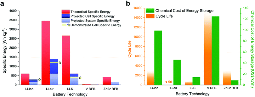 | ||
| Fig. 1 Bar charts comparing the relative performance of Li-ion batteries (the commercial state of the art) versus the main emerging battery technologies covered in this review (vanadium-based redox flow batteries are the most heavily commercialised RFB, though Zn–Br cells are emerging as an interesting alternative and are provided here for comparison). All metrics are provided on the basis that RAMs have not been used to improve performance (excepting in RFBs, where they are the primary charge carrier). Note: cycle life is defined as the number of charge–discharge cycles the battery can perform before its effective capacity drops below 80% of maximum. Given the difficulty in extracting an absolute value for this metric, the faded bars are provided as an approximation of the ranges in which the best-performing systems might exist and are provided here as a guide for ease-of-comparison. The chemical cost of energy storage is a metric which accounts for the approximate cost of the main chemical components of the cell (the electrodes, electrolyte and solvent) and excludes the cost of the cell itself and any other necessary equipment in the pack (e.g., pumps, compressors, separators). Data for these plots has been compiled from ref. 7 and ref. 9–ref. 13. | ||
These factors have prompted greater interest in the development of new “beyond Li-ion” technologies employing higher energy density metallic or alloy-based negative electrodes. Numerous approaches are currently being studied, exploring a range of different negative electrode materials (typically lithium, sodium, magnesium, aluminium, calcium, and zinc) and lightweight chalcogen-based (i.e. oxygen and sulfur) positive electrodes. In comparison to mature LIB technologies, these approaches are still in their infancy and most fall outside the scope of this tutorial review, though they have been described in detail elsewhere recently.7 The most promising specific energies are offered by the lithium–air (Li–air),8 and lithium–sulfur (Li–S) batteries (see the corresponding sections below on pages 4 and 9, respectively, for more detailed descriptions of both technologies),9 which are capable of achieving paradigm-shifting energy densities of ca. 1400 W h kgcell−1 and 610 W h kgcell−1, respectively, through the combination of ultra-high capacity metallic Li negative electrodes with elemental chalcogen positive electrodes (O2 or S). The relative performance of the current commercial state-of-the-art batteries and emerging next-generation technologies is summarised in Fig. 1.8,10–14 In a device, taking into account pack and system overheads, this would result in practical specific energies in excess of 450 W h kg−1 compared to 165 W h kg−1 for Li-ion. However, significant chemical and engineering challenges must be solved, as evidenced by the low cycle life.
Whilst these ‘beyond Li-ion’ batteries are therefore extremely attractive targets as ultra-high energy density alternatives to LIBs in applications requiring portability, grid-scale EES is typically much more sensitive to parameters such as discharge time (often requiring days rather than hours, as provided by LIBs) and favours very high cycle lifetimes over specific energy density. Most of all, grid-scale EES is highly cost sensitive, and recent projections have indicated that an energy storage cost of ca. 150 $ per kW h would be required in a 95% renewable-based grid to achieve cost-competitiveness (this falls to 20 $ per kW h in a fully renewable grid, assuming storage which ensures uninterrupted supply).15 Historically, LIBs have struggled to meet these criteria and though costs have decreased dramatically in recent years, incentivising a number of pilot-scale projects such as the Horndale Power Reserve in Southern Australia (rated for 129 MW h at a capital cost of ca. $66 M – or, crudely, ca. $510 per kW h), this remains a significant barrier to the widespread adoption of LIBs in EES. As such, several alternative technologies have been explored, including Pb-acid and high temperature Na–S and Na–NiCl batteries.16 These are historically cheaper than LIBs and, in the case of the molten–Na batteries, have considerably longer cycle lifetimes (though at the cost of requiring constant heating to keep the electrolyte molten, lessening their overall efficiency). One of the more promising technologies to emerge as a direct competitor for LIBs in larger scale EES applications is the redox flow battery (RFB).17 Unlike the LIB, the RFB operates by storing soluble molecular charge carriers (CCs) (most commonly vanadium salts) in external reservoirs which can then be pumped through the electrochemical cell to charge or discharge the battery as required (described in detail in the corresponding section below, see Fig. 14). This unique design allows decoupling of capacity (via the total reservoir volume) and power (via the electrode size and cell design), imparting huge flexibility and scalability towards a variety of distributed storage or microgrid applications (such as the 800 MW h Rongke Power project in Dalian, China). In particular, RFBs benefit from very high cycle lifetimes (as much as 5–10 times higher than LIBs, theoretically allowing them to run for over a decade without significant capacity loss) and are expected to be cost-competitive with most existing EES technologies, though at the expense of overall specific energy density (see Fig. 1).
The role of molecular species in next-generation batteries
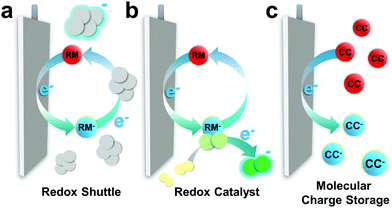
While the development of the LIB was dominated by advances in solid state chemistry, which underpinned the discovery of new intercalating electrode materials, the next-generation of batteries will typically require innovations based on molecular chemistry operating in either the solution phase (the electrolyte), or at the solid–liquid interface and the ionically conducting phase that forms there (often referred to as the solid–electrolyte interphase (SEI)).18 Molecular chemistry will be the key driving force in the design of new electrolytes and additives for the next-generation of energy storage technologies. This is because, in contrast to LIBs, the redox reactions in many of these new batteries occurs in the liquid phase and tuning both the electrolyte environment, and the properties of redox additives within the cell, offers significant opportunity to optimise device performance. The implementation of redox-active molecules (RAMs) has emerged as a particularly important strategy for a range of battery technologies. A summary of their primary modes of action is provided in Fig. 2,19,20 and details of their roles in different technologies can be found in Sections 2–4.RAMs can function as redox mediators (RMs) between the electrodes and active material,20–22 limiting formation of resistive solids which can lead to electrode passivation, a common problem in batteries which operate by cycling through insulating phases (e.g. Li2O2 in Li–air batteries). This approach has also found application in systems containing dissolved substrates with poor mass transport (either due to mobility or concentration) and here RMs can compensate for intrinsic deficiency of the cell chemistry, particularly at high rates (i.e. current). RMs can also act as catalysts, binding active material or intermediates and lowering the barrier to electron transfer or shifting reaction pathways (replicating the role of an electrocatalyst). Again, this function is particularly important in “beyond-LIB” technologies such as Li–air and Li–S batteries, where the RM minimises formation of potential-determining intermediates (i.e., specific products in the cycling process that require high overpotentials) and provides access to low energy reaction pathways, improving the energy efficiency of the cell.
RAMs are also the primary charge carriers within the RFB.17,22 As discussed above, here two concentrated solutions (typically > 1 M) of RAMs are simultaneously oxidised/reduced on each side of the cell, resulting in an overall transfer of one (or more) electron(s) between the components (see Fig. 14, Section 4). The RAMs are directly responsible for determining the specific energy of the battery, based on their maximum solubility, the number of electrons by which they can be oxidised/reduced, and their redox potentials.
In all scenarios, the RAM is not consumed and is fully regenerated following each charge/discharge cycle. The most important advantage of these molecular redox additives is that they allow for substantial optimisation of their performance through systematic molecular design across a very wide range of different chemistries (ranging from organic, to organometallic and fully inorganic systems). Careful modification of the molecular structure can be used to control a range of critical parameters and determine its effectiveness as a CC and/or effective electron-transfer catalyst within the cell. This can include potential matching with a target redox couple (such as that of the active CC or a specific intermediate in order, for instance, to reduce overpotentials and improve the cell energy efficiency); improving electron transfer kinetics to enhance performance under high charge/discharge rates; tuning solubility and ease-of-diffusion through the electrolyte, and; engineering long-term chemical, electrochemical and thermal stability to improve device lifetime. As the possible library of RAMs is vast and spans a wide range of different chemistries, a nearly limitless range of chemical strategies exist in order to address these challenges. A broadly representative range of different RAMs (acting as both RMs and CCs) and their application to next-generation batteries is discussed in detail through Sections 2–4 below.
Scope of this review
This tutorial review will aim to provide a concise overview of the role of RAMs in three of the most promising and thus heavily researched next-generation EES technologies: the lithium–air (Li–air), lithium–sulfur (Li–S) and redox flow batteries (RFB). Li–air and Li–S batteries offer the highest practical specific energies of 450 W h kg−1 and >500 W h kg−1 (at the system level) of any secondary battery technology currently under serious consideration,2,6 whilst the RFB is a leading contender for larger-scale stationary EES due to its low lifetime cost, long lifespan and excellent reliability.11,17,23 Note that for brevity this tutorial review will focus exclusively on molecular approaches. While it should be noted that there are examples of simple ionic species acting as mediating species in Li–air and Li–S batteries (e.g. Li–I, LiNO3),24 and that the history of RFB development is littered with examples of the use of simple metal salts and various halides etc.,17 we will therefore limit our focus to the much more recent development of truly molecular systems which we contend may give a more useful picture of where the future of the field lies. Each technology will be introduced in detail below and the critical role of RAMs, as applicable to each battery type and its particular chemistry, will be explored via the discussion of selected recent examples from the literature. An indication of the scope for targeted molecular design of the RAM and its use as a means to improve specific features of battery performance will be provided. Ultimately, this tutorial review is intended to enlighten both synthetic chemists and electrochemists alike to the pressing need for new cross-disciplinary efforts to realise the immense potential of RAMs in unlocking the next-generation of electrochemical energy storage technologies.Lithium–air batteries
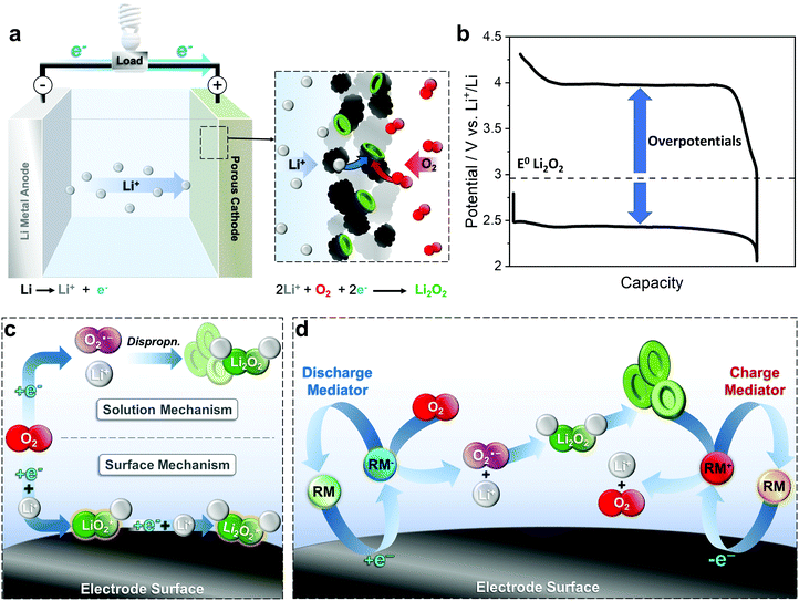
The lithium–air battery is of special interest due to its remarkable theoretical specific energy density (3505 W h kg−1), the highest of any “beyond Li-ion” battery currently in development. The battery consists of a porous positive electrode (cathode), a lithium negative electrode (anode) and a non-aqueous solvent-based electrolyte (Fig. 3a). During discharge, O2 is reduced at the positive electrode to Li2O2, with the Li metal electrode undergoing oxidation to Li+ ions. This chemistry differs from that found in the LIB (where the Li+ ions are intercalated into a metal oxide), as a new phase, Li2O2, is formed within the porous positive electrode.1,2 Lithium superoxide, LiO2, has also been reported as a discharge product, though less commonly, and typically requires functionalised carbon electrodes to promote the superoxide over the peroxide.25,26 The lack of heavy transition metals at the positive electrode eliminates much of the mass, which is the origin of the very high specific energy of the Li–air battery. In a practical Li–air battery however, additional components such as a gas-handling system (balance of plant) are required to deliver dry air to the cell, resulting in a practical energy density at a system level of >500 W h kgsystem−1.8 To achieve this, a cell would require Li2O2 to comprise 60 vol% of the carbon electrode at the end of discharge while minimising the excess lithium in the negative electrode. Note that due to the additional challenges of operating in air, most research is currently reported using pure oxygen and as such, is technically performed on lithium–oxygen (Li–O2) cells, rather than Li–air.Controlling the reversible formation and decomposition of solid, insulating Li2O2 at the positive electrode is a major challenge and the focus of most research to date. The reaction pathway during cycling consists of two consecutive Li+ ion-coupled electron transfer reactions via a lithium superoxide, LiO2, intermediate (eqn (1) and (2)):
| O2(sol) + e− + Li(sol)+ → LiO2 | (1) |
| LiO2 + e− + Li(sol)+ → Li2O2(s) | (2) |
| 2LiO2 → Li2O2(s) + O2(sol) | (3) |
However, the intermediate LiO2 can also undergo a disproportionation reaction (eqn (3)). During discharge, Li2O2 can form via one of two mechanisms, a surface or a solution route. In the former, O2 is initially reduced to LiO2 on the electrode surface, before undergoing a subsequent electrochemical reduction to form thin films of the final Li2O2 product (Fig. 3c). In the latter mechanism, O2 is reduced at the electrode to superoxide, O2−, which can dissolve into solution and disproportionate to Li2O2. During charge, the Li2O2 decomposes, releasing O2 and Li+ and herein lies the major challenge in development of a practical cell. Most electrolytes are unable to support discharge via the solution route and as a result, insulating Li2O2 builds up on the electrode surface rendering further O2 reduction progressively more difficult and eventually passivates the electrode surface completely, prematurely terminating the discharge and reducing the overall capacity of the cell.27–29 In practice, a Li2O2 film of just 7 nm is enough to passivate the electrode, which severely limits the target formation of 60% Li2O2 by volume on discharge, making the high theoretical capacity of this system impossible to obtain in reality.8 On charge, the insulating properties of Li2O2 also presents a significant challenge and typically requires a large overpotential (e.g. a typical Li–O2 cell charges at over 4 V vs. Li+/Li), which negatively impacts the efficiency of the cell and can induce degradation of the solvent or electrolyte, resulting in cell failure.28,30 Furthermore, only Li2O2 on the electrode surface can be effectively oxidised and any particles without direct electrical contact cannot participate in the charging process, dramatically reducing the capacity of the battery.8,20,31
RAMs which can be employed as redox mediators have been identified as a critical tool in order to address these challenges.21 By decoupling electrochemical reduction at the electrode from the formation of Li2O2, they can effectively prevent passivation of the electrode surface by promoting a solution-phase mechanism over a surface confined one (Fig. 3d).28,32–34 Rather than directly reducing O2 at the positive electrode, the RM is first reduced and diffuses from the electrode where it can then reduce O2 in solution, thus acting as a redox shuttle(Fig. 2a). The resulting O2− can then undergo further reduction by a second RM or disproportionate to ultimately form Li2O2, though crucially, this occurs in the solution phase, greatly improving the accessible surface area of the electrode and thus the overall cell capacity.32,34 It should be noted that simple redox shuttles are, however, unable to stop surface passivation entirely as direct reduction of the LiO2 intermediate can still occur on the electrode. Here, a RM able to act as a redox catalyst (able to reduce O2 to Li2O2via a mediator-LiO2 complex) is required (Fig. 2b).28,33 Furthermore, though promoting the solution-phase mechanism alleviates the issue of low discharge capacities, it also exacerbates problems with poor cell cyclability, since any Li2O2 formed in solution typically has poor electrical contact to the positive electrode and thus cannot be re-oxidised on charging.28,32–34 In this scenario, a RM is also essential for oxidation of the vast majority of the Li2O2 formed in solution.29,33 In this case, the charging potential is set by the redox mediator and is typically lower than that found in the direct oxidation of solid Li2O2 (due to its high overpotential).8 Provided the redox potential of the RM is >2.96 V (vs. Li+/Li) then it should be capable of oxidising any Li2O2 in the cell. In particular, mediators operating at potentials between 3.0 and 3.5 V are desirable as this helps increase overall energy efficiency.31,35 While simple inorganic species such as halides and nitrate have shown significant improvements compared to mediator-free cells, charging still often occurs at >3.5 V and therefore the search for redox mediators has since shifted to more complex molecular redox species.8,20,24 In the following, we provide an overview of several of the different molecular strategies used to tailor RAM additives to improve Li–air battery performance and lifetime.
Metal-centred redox mediators
Inorganic and organometallic species incorporating transition metals are particularly attractive targets as redox mediators because they often possess tuneable and/or multi-redox properties, often with fast electron transfer kinetics and excellent redox stability. One of the first and simplest organometallic species investigated as a mediator was ferrocene, with a redox potential at ∼3.6 V vs. Li+/Li. Bruce and co-workers demonstrated that mixing a ferrocenium solution (generated electrochemically via oxidation of ferrocene) with Li2O2 powder results in the release of O2 gas, which was detected using on-line mass spectrometry.31 Curtiss, Salehi-Khojin and co-workers compared several redox mediators, including ferrocene and a derivative, (dimethylaminomethyl)ferrocene.24 Both compounds were shown to reduce the charge potential to <3.5 V on the first cycle, indicative of efficient Li2O2 oxidation. However, on subsequent cycles, the charging overpotential increased rapidly and cyclic voltammetry measurements showed that the reversibility of both species decreased with increasing cycle number. The authors attributed this to the mediators reacting irreversibly with singlet oxygen, known to form during charge, which would preclude their use in a practical lithium–air battery.8,24Similar findings were obtained for cobalt bis(terpyridine) ([Co(tpy)2]).36 Cells cycled with 50 mM [Co(tpy)2] in the electrolyte had an initial charge plateau of ∼3.35 V vs. Li+/Li, though again this steadily rose throughout the charge. In situ analyses confirmed that the e−/O2 ratio was 2.3, suggesting parasitic side reactions (a cell undergoing stable cycling would provide an e−/O2 ratio of 2, consistent with the 2e− reduction of O2 to Li2O2). Furthermore, the O2 evolved during charge was only 23% of the quantity consumed on discharge. Despite its ability to mediate charging, these issues mean that [Co(tpy)2] was not ultimately suitable as a charge mediator.
Shen, Huang and co-workers reported the use of iron phthalocyanine as a bifunctional catalyst.33 They proposed that the Fe centre interacts with O2, facilitating the first reduction at the electrode and acting as a classic electrocatalyst (i.e. does not carry charge). LiO2 and Li2O2 also bind effectively to this mediator, facilitating their transport into the electrolyte and allowing the formation of large Li2O2 particles away from the electrode surface. A similar mechanism operates on charge, where Li2O2 is oxidised to LiO2 while bound to the RM, before being further oxidised at the carbon positive electrode. Cells cycled with iron phthalocyanine thus achieved greater discharge capacities than mediator-free cells, and with lower overpotentials, but the charging potential remains high (above 3.6 V and up to 4.4 V). While this work demonstrates the potential of bifunctional RMs, further development to tune the redox processes so they fall within the necessary potential windows for efficient discharge and charge is required.
Polyoxometalates (POMs) have been also recently been used as RMs for Li–O2 batteries due to their multiple, and highly reversible sequential redox couples. Recently, Garcia-Araez and co-workers demonstrated the use of a Keggin-type [α-SiW12O40]4− POM cluster, to promote discharge in a Li–O2 cell.34 The capacity essentially tripled compared to that of mediator-free cells (0.6 mA h cmcarbon−2vs. 0.2 mA h cmcarbon−2), indicating that the POM effectively enhanced the solution-phase growth of Li2O2 by reducing O2 in the bulk electrolyte (Fig. 4). Furthermore, in situ pressure measurements demonstrated that the e−/O2 ratio was ∼2, indicating that the predominant electrochemical reaction is Li2O2 formation and the POM does not induce parasitic reactions. One key advantage in this system over other types of RM is the expected stability of such clusters to reactive oxygenic species formed in situ, which can oxidatively decompose other organic/organometallic species. The coulombic efficiency of the POM-mediated cell was poor however, as might be expected when the solution mechanism is promoted in the absence of a charge mediator to promote the reverse reaction. This serves to highlight the critical role that RMs can play in both charge and discharge processes in Li–air batteries especially.
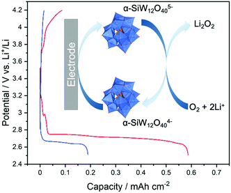 | ||
| Fig. 4 Cycling profiles of a Li–O2 cell containing [α-SiW12O40]4− (red trace) and a mediator-free cell (blue trace) showing a three-fold increase in discharge capacity when using the POM RM. Shown inset is the proposed mechanism of Li2O2 formation using α-SiW12O404− as a mediator. Adapted from ref. 34 with permission from the Royal Society of Chemistry. | ||
Organic redox mediators
The vast majority of redox mediators reported thus far are organic in nature and are typically aromatic and/or heterocyclic molecules.8,20 Aromatic molecules in particular, are well-suited as RAMs because their delocalised π systems afford significant stability to the radical cation/anion generated by their 1e− oxidation/reduction, respectively. Furthermore, the addition of functionalised side groups or heteroatoms into the π system allows the redox potential of these species to be broadly tuned by altering the stability of the resultant cation/anion. Consequently, numerous delocalised quinone-, thioether- and amine-based mediators have been identified and explored as RMs for Li–O2 batteries.The first organic RAM to be successfully employed as an added redox mediator was tetrathiafulvalene (TTF) by Bruce and co-workers.31 The oxidation of TTF produces aromaticity in one of the thioether rings, which enables the subsequent oxidation of Li2O2 to dioxygen, (Fig. 5a). Remarkably, cells containing TTF were successfully cycled 100 times using a gold positive electrode (note: non-mediated Li–O2 cells typically struggle to cycle more than 10 times before suffering dramatic capacity fade). Here, the electrolyte also contained dimethyl sulfoxide (DMSO), which supports formation of Li2O2via the solution mechanism and, consequently, gives rise to similar charging issues to those discussed above (where the Li2O2 formed in solution during discharge has little or no electrical contact with the electrode necessary for charging). Introduction of TTF resulted in charging with 100% coulombic efficiency at current densities up to 1 mA cm−2 (Fig. 5b). Better still, the charge potential was also found to be ∼3.5 V vs. Li+/Li (corresponding to the redox potential of TTF), which is lower than that required to oxidise Li2O2 directly.
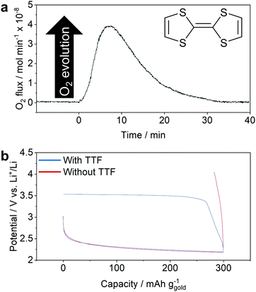 | ||
| Fig. 5 (a) On-line mass spectrometry confirming Li2O2 oxidation via real time monitoring of O2 evolution when TTF+ was added to a sample of Li2O2; (b) cycling profiles in a prototypical Li–O2 cell demonstrating that TTF is required to oxidise Li2O2 particles formed (via the solution mechanism) on discharge in a DMSO-based electrolyte. Adapted with permission from ref. 31. Copyright 2013 Springer Nature. | ||
Nazar and co-workers studied tris[4-(diethylamino)phenyl]amine (TDPA) as an oxidation/charge mediator.35 TDPA has two redox couples suitable for Li2O2 oxidation (at 3.1 V and 3.5 V vs. Li+/Li), corresponding to the TDPA/TDPA+ and TDPA+/TDPA2+ couples, respectively (Fig. 6a), allowing a significant decrease of the cell charging potential (Fig. 6b). The authors proposed that TDPA+ initially oxidises Li2O2 but as charging proceeds, TDPA is regenerated too slowly and consequently, TDPA+ undergoes further oxidation to TDPA2+. Unlike TDPA+, this can directly oxidise Li2O2 to O2 in a single step and thus sustain higher charge rates. Cells containing TDPA were able to demonstrate 100 cycles with a limited capacity of 1000 mA h gcarbon−1, as compared to mediator-free cells which failed after 40 cycles. On-line mass spectrometry showed that addition of TDPA resulted in almost exclusive O2 evolution, unlike a non-mediated cell which evolves CO2 due to oxidation of Li2CO3 and/or organic carboxylates and is indicative of unwanted degradation reactions within the cell (Fig. 6c and d). 1H NMR measurements also suggested that TDPA was stable over multiple discharge/charge cycles, a key criterion for a redox mediator.
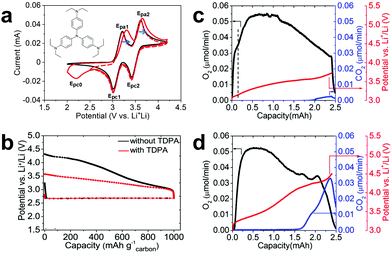 | ||
| Fig. 6 (a) Cyclic voltammetry of TDPA in the presence (red traces) and absence (black trace) of O2 in a Li+-containing electrolyte. This identified two sequential redox processes corresponding to oxidation of TDPA to TDPA+ and TDPA2+; (b) cycling profiles showing a significant decrease in charging potential using TDPA (red trace) as compared to a mediator-free cell (black trace); (c) on-line mass spectrometry demonstrating increased O2 (black trace) and reduced CO2 evolution (blue trace) in a cell charged with TDPA, and; (d) equivalent measurements in a non-mediated cell, indicating efficient Li2O2 oxidation and suppressed parasitic reactions when using a suitable RM. Adapted with permission from ref. 35. Copyright American Chemical Society 2015. | ||
Janek and co-workers reported the use of the common nitroxide, 2,2,6,6-tetramethylpiperidinyloxyl (TEMPO).30 The redox potential for TEMPO is 3.74 V vs. Li+/Li, which is notably higher than other RMs discussed above but its addition to a Li–O2 cell still leads to an improved charging voltage compared to unmediated cells (Fig. 7a and b), and enables oxidation of Li2O2 with no direct contact to the electrode surface (Fig. 7c and d). The authors compared the cycling of cells containing TEMPO and TTF and found that oxidation potentials increase with cycle number in both cases, but more slowly in the former, suggesting that TEMPO would be more suitable for long-term cycling of cells. The polarisation was ascribed to the build-up of parasitic discharge products and/or decomposition of the mediators due to formation of reactive intermediates (it has since been shown that many mediators react irreversibly with oxygenic intermediates, for instance).8 TEMPO also decreases O2 solubility in the electrolyte from 6.6 mM in mediator-free electrolyte to 5.2 mM with 100 mM TEMPO present and further studies have shown that when using TEMPO to lower the charging potential, the degree of oxidative decomposition of the porous carbon electrode is also lowered.29 Further studies have also recently shown that TEMPO is a high rate mediator and able to maintain charging currents of 1 mA cmcarbon−2.27
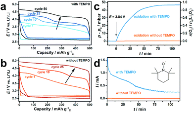 | ||
| Fig. 7 Cycling profiles of Li–O2 cells: (a) with, and; (b) without TEMPO, showing the decrease in charge potential when employing a redox mediator; (c) TEMPO redox shuttling was confirmed by oxidising Li2O2 sandwiched between separators (i.e. disconnected from the electrode) by monitoring O2 evolution, and; (d) the current, with and without TEMPO (orange and blue traces, respectively) while applying a potential of 3.84 V vs. Li+/Li. Using the RM, O2 evolution corresponding to formation of 92% of the maximum Li2O2 in the electrode was recorded. Adapted with permission from ref. 30. Copyright 2014 American Chemical Society. | ||
Several organic discharge RMs have been identified, for example, ethyl viologen, which has been shown to more than double discharge capacities.32 Ethyl viologen can be reduced from the +2 oxidation state to either the +1 state or neutral species, thus allowing it to reduce O2 to either LiO2 or Li2O2, respectively. However, the discharge potential of Li–O2 cells containing ethyl viologen was ∼2.4 V, similar to the mediator-free cells, indicating LiO2 can still form electrochemically. Therefore, to suppress the surface mechanism, one must avoid the generation of the LiO2 intermediate, whether it exists on the electrode surface or in solution, as this will inevitably disproportionate and passivate the electrode with Li2O2,28 thus requiring a new reaction pathway to be developed.
Bruce and co-workers successfully reported the first discharge mediator able to avoid direct oxygen reduction and the formation of the LiO2 intermediate in an electrolyte (Fig. 8a).28 The authors employed a functionalised quinone, 2,5-di-tert-butyl-1,4-benzoquinone (DBBQ), and proposed that on reduction to DBBQ− (or Li–DBBQ), it would associate with dioxygen to form a Li–DBBQ–O2 adduct able to freely diffuse throughout the electrolyte (Fig. 8c). Li2O2 could subsequently form from either disproportionation of two Li–DBBQ–O2 complexes, or from the reduction of one such complex with Li–DBBQ (in both cases DBBQ is regenerated, completing the catalytic cycle). Voltammetric analysis (Fig. 8a) suggested the formation of an Li–DBBQ–O2 intermediate, and the authors note here that DBBQ is neither acting as a conventional electrocatalyst (stabilising a superoxide intermediate by binding O2 directly), nor as a conventional redox shuttle (reducing O2 to LiO2 directly in solution). Rather, it modifies the O2 reduction pathway, avoiding the formation of a reactive LiO2 intermediate altogether. Introduction of DBBQ increased the discharge capacity by 80–100 times through a range of current densities when compared to mediator-free cells (Fig. 8b) and large Li2O2 particles were observed when employing the RM, compared to thin passivating films in the non-mediated cells (Fig. 8d and e).
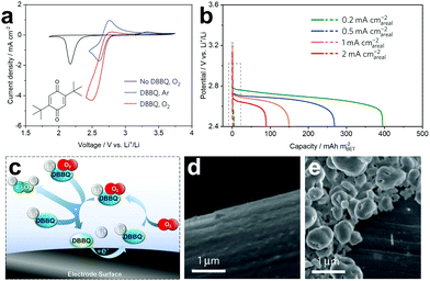 | ||
| Fig. 8 (a) Cyclic voltammograms demonstrating the catalytic effect of DBBQ on O2 reduction; (b) discharge profiles showing the significant increase in capacity when cells are cycled with DBBQ, compared to mediator-free cells (dashed box); (c) schematic of the DBBQ reduction mechanism showing the formation of a new Li–DBBQ–O2 adduct and subsequent Li2O2 formation via disproportionation or further reduction; (d) SEM micrograph of a mediator-free cell following discharge showing the surface-driven plating of Li2O2, and; (e) SEM micrograph of a RM containing cell showing Li2O2 particles forming by a solution-phase mechanism. Adapted with permission from ref. 28. Copyright 2016 Springer Nature. | ||
Summarising the examples of molecular RMs applied in Li–air batteries discussed above, it is clear that both the charge and discharge reactions require suitable mediators in order to ensure that the battery can operate with 100% coulombic efficiency (e.g. maximising both the discharge capacity, by preventing passivation of the electrode, and ensuring that all available Li2O2 in the cell can be re-oxidised efficiently on charging). While bifunctional redox mediators have been demonstrated (e.g. iron phthalocyanine, discussed above),33 finding a single species which combines all of the necessary properties can be challenging. An alternative strategy is to combine individual discharge and charge mediators in a single cell and one of the most successful examples of this approach was recently reported by Bruce and co-workers, who combined DBBQ and TEMPO RMs (targeting discharge and charge processes, respectively) and were able to achieve up to 50 cycles at a high current density of 1 mA cmcarbon−2.29 Despite limiting the discharge capacity to 2 mA h cmcarbon−2, the capacity was 20 times higher than in a mediator-free cell (Fig. 9a and b). The efficacy of this combination of mediators can be seen in SEM images of the carbon-fibre positive electrodes after cycling, where the electrode was covered by large particles of Li2O2 after discharge via the action of DBBQ (Fig. 9c), while following charge, virtually all of the Li2O2 had been re-oxidised via the TEMPO RM (Fig. 9d).
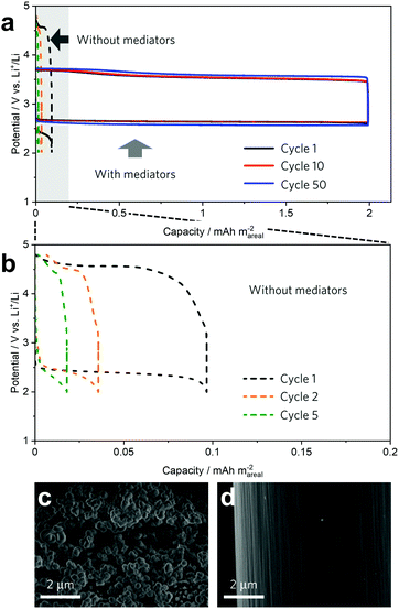 | ||
| Fig. 9 (a) Selected cycling profiles of dual mediator (employing DBBQ and TEMPO) and mediator-free Li–O2 cells, showing a 20-fold improvement in capacity with no capacity fading and reduced overpotentials when using RMs; (b) magnified views of the mediator-free cycling profiles shown in (a), above; (c) SEM micrograph of a carbon electrode cycled with dual mediators after discharge, showing the mediated solution-phase growth of Li2O2 particles which have deposited on the electrode surface, and; (d) SEM micrograph of the electrode after charge, highlighting the near complete oxidation of the Li2O2 in the presence of a suitable RM. Adapted with permission from ref. 29. Copyright 2017 Springer Nature. | ||
Redox-active molecules will play a crucial role in realising the predicted practical specific energy of lithium–air batteries, which necessitates filling of the porous positive electrode with ca. 60 vol% Li2O2. Molecules spanning a wide range of chemistries have been shown to operate as charge and/or discharge mediators. This opens the door to the next generation of RAMs, with optimised redox properties, which could be achieved in part by rationally designing novel molecules through functionalisation of these previously identified mediators. However, any promising RAMs will not only have to demonstrate enhanced discharge capacities and coulombic and energy efficiencies, but also superior stability to the oxygenic environment of the lithium–air battery for hundreds of cycles, which is not trivial.
Lithium–sulfur batteries
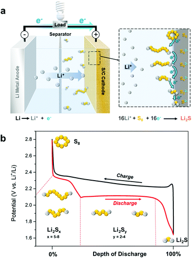
In parallel to the development of Li–air technology, Li–S batteries have emerged as a highly promising alternative to Li-ion due in large part to the high theoretical capacity (not to mention natural abundance and low cost) of elemental sulfur (1672 mA h g−1), which gives rise to the system's impressive theoretical specific energy of 2567 W h kg−1 (using a metallic lithium negative electrode/sulfur positive electrode).1,2,9 The battery operates with a lithium metal negative electrode and either sulfur or lithium sulfide on a conductive support as the positive electrode, and relies on the interconversion of sulfur (S8) and lithium sulfide (Li2S). The typical positive electrode consists of a 3D carbon architecture within which the insulating sulfur/sulfide is housed. An electrolyte containing Li+, typically 1 M lithium bis(trifluoromethane)sulfonimide (LiTFSI) and 1–5 wt% LiNO3 is dissolved in a 1![[thin space (1/6-em)]](https://www.rsc.org/images/entities/char_2009.gif) :
:![[thin space (1/6-em)]](https://www.rsc.org/images/entities/char_2009.gif) 1 mixture of 1,3-dioxolane (DOL) and 1,2-dimethoxyethane (DME).37 LiTFSI provides ionic conductivity between the two electrodes and LiNO3 is used as an additive to stabilise the metallic lithium interphase (Fig. 10a).2 Despite the excellent theoretical performance of the Li–S battery, translating this into a real-world cell able to supersede Li-ion batteries remains challenging. To be viable, a practical cell must contain a S/C volume ratio of 2
1 mixture of 1,3-dioxolane (DOL) and 1,2-dimethoxyethane (DME).37 LiTFSI provides ionic conductivity between the two electrodes and LiNO3 is used as an additive to stabilise the metallic lithium interphase (Fig. 10a).2 Despite the excellent theoretical performance of the Li–S battery, translating this into a real-world cell able to supersede Li-ion batteries remains challenging. To be viable, a practical cell must contain a S/C volume ratio of 2![[thin space (1/6-em)]](https://www.rsc.org/images/entities/char_2009.gif) :
:![[thin space (1/6-em)]](https://www.rsc.org/images/entities/char_2009.gif) 1, operate with a maximum electrolyte volume of 1 mL gsulfur−1, and achieve an S to Li2S conversion on discharge approaching 60%. Assuming these targets are met, a Li–S battery pack with a specific energy of 450 W h kgpack−1 could be achieved.12
1, operate with a maximum electrolyte volume of 1 mL gsulfur−1, and achieve an S to Li2S conversion on discharge approaching 60%. Assuming these targets are met, a Li–S battery pack with a specific energy of 450 W h kgpack−1 could be achieved.12
The electrochemical pathway between S8 and Li2S is complex and presents a sizeable challenge when considering battery design and optimisation. During discharge, reduction of cyclic S8 results in ring opening to produce long chain linear polysulfides, Li2Sn (n = 5–8) resulting in a voltage plateau at ∼2.35 V vs. Li+/Li. Subsequent electrochemical reductions (and the associated chemical reactions) of longer chain polysulfides result in the formation of shorter chain polysulfides (n = 2–5) leading to a second plateau at ∼2.1 V vs. Li+/Li. Complete discharge yields the insoluble terminal reduction products Li2S2 and Li2S (Fig. 10b). This process is reversed upon charging, with the stepwise oxidation and chain growth of Li2S to reform S8 yielding a featureless sloping charge curve. Ideally, these processes would follow a linear electrochemical reduction pathway, however, higher order polysulfides (n = 5–8) can undergo both electrochemical reactions and chemical disproportionation and comproportionation reactions, generating complex mixtures containing a variety of different polysulfide chains.19 In addition, lower order polysulfides (n = 2–4) have such similar Gibb's energies that no one species dominates at any degree of discharge. Unsurprisingly, this multicomponent reaction mixture is affected by numerous parameters such as electrode loading, electrolyte volume and composition, and cycling rate (i.e. current), rendering their absolute characterization difficult.
The complexity of the redox chemistry introduces several challenges during operation of the Li–S cell. Intermediate polysulfides are soluble in a range of electrolytes and often diffuse from the positive electrode to the negative electrode (passing through the separator between), a process termed cross-over that leads to the loss of active lithium metal and sulfur. Polysulfides can also cause an electrochemical short- circuit known as the shuttle effect, where they undergo repeated reduction and oxidation reactions at the negative and positive electrodes, respectively. These unwanted side reactions reduce the active material utilization and hence the coulombic efficiency of the cell. Additionally, this phenomenon causes capacity fade, poor cycling stability and self-discharge. Perhaps the most significant challenge in Li–S battery science however, is the preparation of a cell with a sufficiently high sulfur to carbon ratio and low electrolyte volume such that it can deliver high capacities and high rates, i.e. >1000 mA h gsulfur−1 at 1 C (i.e. a current sufficient to discharge the entire battery in 1 h) or more. All current cells sacrifice rate for capacity and fall short of automotive and aerospace sector targets. Electrodes with high sulfur loadings suffer from low material utilization and large voltage polarization during operation (a problem similar to that experienced due to formation of insulating Li2O2 in Li–air cells), whereas increasing carbon content to counteract this comes at the expense of a lower specific capacity due to the additional weight of ‘inactive’ material.
The application of RAMs is increasingly being explored as a new approach to combat the above issues. Effective use of redox shuttles (see Fig. 2a) can facilitate better utilisation of high loading electrodes and, by accelerating redox kinetics between terminal charge–discharge products, mitigate the dissolution of polysulfide intermediates into the electrolyte (circumventing issues related to polysulfide cross-over). Redox shuttles are typically designed to mediate either S8 reduction (where RMred < 2.4 V vs. Li+/Li) or Li2S oxidation (RMox > 2.15 V vs. Li+/Li) but may also mediate intermediate polysulfide redox reactions in solution. Another unique approach involves the use of S-based mediators which are designed to react with the active material to form new redox pathways with enhanced redox kinetics and electrochemical reversibility. Here we explore the operational principles and impact on cell performance involved with these contrasting approaches.
Metal-centred redox mediators
The same appealing qualities that make transition-metal based RMs excellent candidates for use in Li–air batteries (e.g. their wide-ranging and highly tuneable redox potentials, fast redox kinetics and good stability) also make them highly attractive for use in targeting both charge and discharge processes in Li–S batteries. Indeed, the very first investigation into the viability of RMs in Li–S cells was carried out by Aurbach and co-workers, and targeted the re-oxidation of fully discharged Li2S positive electrodes using metallocenes with redox potentials that were either: more negative than (cobaltocene); equivalent to (dibenzenechromium), or; more positive than (decamethylferrocene and ferrocene) the oxidation potential of Li2S (2.15 V vs. Li+/Li).38 This was also compared to the inorganic RM, lithium iodide, which operates through the I−/I3− redoxcouple (Fig. 11a). The authors demonstrated that only those with more positive redox potentials than Li2S functioned as charge mediators for Li2S oxidation. Their activity was confirmed by the presence of a potential plateau which dominates the charging domain, approximately corresponding to the half-wave potential of the RM as observed in the cyclic voltammogram (Fig. 11b). The most effective RM for increasing Li2S utilization was decamethylferrocene which led to an initial charge capacity of ∼950 mA h gLi2S−1 (cf. ∼520 mA h gLi2S−1 with no RM), a reversible capacity of >490 mA h gLi2S−1 after 150 cycles (cf. <120 mA h gLi2S−1 with no RM) and a reduction in overpotential from 4.0 to 3.2 V.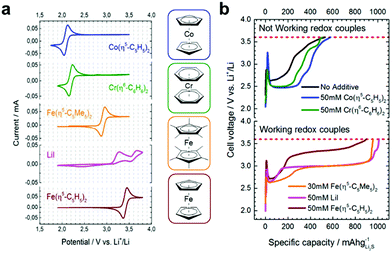 | ||
Fig. 11 (a) Cyclic voltammograms of various metallocenes and lithium iodide vs. Li+/Li (5 mM solutions in 1![[thin space (1/6-em)]](https://www.rsc.org/images/entities/char_2009.gif) : :![[thin space (1/6-em)]](https://www.rsc.org/images/entities/char_2009.gif) 1 DOL 1 DOL![[thin space (1/6-em)]](https://www.rsc.org/images/entities/char_2009.gif) : :![[thin space (1/6-em)]](https://www.rsc.org/images/entities/char_2009.gif) DME containing 10% LiTFSI and 2% LiNO3); (b) charge curves obtained using each of the RMs (shown right) taken from coin cells containing 60 μL electrolyte (50 mM solutions in 1 DME containing 10% LiTFSI and 2% LiNO3); (b) charge curves obtained using each of the RMs (shown right) taken from coin cells containing 60 μL electrolyte (50 mM solutions in 1![[thin space (1/6-em)]](https://www.rsc.org/images/entities/char_2009.gif) : :![[thin space (1/6-em)]](https://www.rsc.org/images/entities/char_2009.gif) 1 DOL 1 DOL![[thin space (1/6-em)]](https://www.rsc.org/images/entities/char_2009.gif) : :![[thin space (1/6-em)]](https://www.rsc.org/images/entities/char_2009.gif) DME, 10% LiTFSI, 2% LiNO3) ran at 0.2 C with a cut off voltage of 3.6 V vs. Li+/Li. Adapted with permission from ref. 38. Copyright 2014 American Chemical Society. DME, 10% LiTFSI, 2% LiNO3) ran at 0.2 C with a cut off voltage of 3.6 V vs. Li+/Li. Adapted with permission from ref. 38. Copyright 2014 American Chemical Society. | ||
Metallocenes have also been demonstrated to improve cell performance during discharge by targeting polysulfide reduction. Sung and co-workers reported the discharge of an ultra-high sulfur content positive electrode (80 wt%) using cobaltocene, the redox potential of which is 2.0 V vs. Li+/Li (i.e. slightly negative of the polysulfide reduction to Li2S at 2.05 V).39 The cobaltocene mediated polysulfide reduction in both the electrolyte and directly at the electrode surface, leading to increased Li2S formation and a thicker Li2S layer on the electrode. After 10 cycles the cell with cobaltocene displayed a 3-fold capacity increase versus the non-mediated cell (750 vs. 250 mA h gsulfur−1) and appreciable performance at high discharge rates, though it did however, show considerable capacity fade after 7 cycles.
The redox targeting principle demonstrated with metallocenes has also found application in rechargeable Li–S redox flow batteries (Li–S RFB).40 Unlike conventional RFB systems (see Fig. 14, below), the fundamental redox reaction occurs between two non-flowing components (solid sulfur stored in a separate reservoir and a conventional Li metal negative electrode in the electrochemical cell) (Fig. 12). A pair of RMs shuttle electrons between the lithium and the sulfur/sulfide active material stored in the reservoir (the sulfur is incorporated into a polymer to prevent dissolution), where reduction during discharge is mediated by decamethyl chromocene (E1/2 = 1.96 V vs. Li +/Li) and oxidation during charge by decamethyl nickelocene (E1/2 = 2.49 V). The initial discharge capacity was ∼765 mA h gsulfur−1, corresponding to 0.92e− per S atom, suggesting that insoluble Li2S2 is the main discharge product. After the first 5 cycles, a coulombic efficiency of >99.5% and an energy efficiency of 75% was obtained. Unfortunately, the system showed pronounced capacity fade over the first 20 cycles suggesting polysulfide crossover through the membrane. The authors suggest that the relatively low driving force between decamethyl chromocene and Li2S (100 mV) may not be adequate to suppress polysulfide formation, however the principle of RM molecular design is clearly demonstrated here, as the decamethyl metallocenes have more suitable redox potentials than the native metallocenes for targeting the fundamental reactions in the cell.
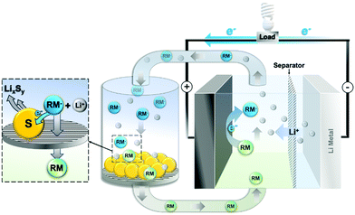 | ||
| Fig. 12 Schematic of a Li–S RFB operating under discharge, highlighting the fundamental charge transfer steps between the RMs, electrodes and active material. | ||
Organic redox mediators
Fully organic RMs have also been explored as targeted mediators for Li–S cells. Helms and co-workers developed an approach for targeting the reduction of Li2S4 to Li2S using organic RMs with specific redox potentials (∼2.1 V vs. Li+/Li).41 High throughput computational screening using calculated electron affinities and ionization potentials identified benzo[ghi]peryleneimide (BPI) as a promising candidate. Electrochemical analysis showed that this RM has a reversible reduction at 1.98 V vs. Li+/Li in diglyme/LiTFSI/LiNO3, which provided an adequate (∼100 mV) driving force for the reduction of polysulfides. Interestingly, while computational screening was successfully used to identify BPI, the practical RM had to be modified with two tri(ethylene oxide) substituents to improve solubility, neatly highlighting the need to couple both analytical and synthetic approaches. The addition of BPI to the cell more than doubled the capacity compared to the control (691 vs. 316 mA h gsulfur−1) due to a greatly extended voltage plateau at 2.0 V indicating increased Li2S formation. Post-mortem analysis of the positive electrode revealed that the BPI appeared to encourage Li2S to grow outwards and away from the electrode surface instead of forming a passivating film.Similarly to metallocenes, organic RMs can also be successfully used in Li–S flow cells. Lee and co-workers extended their tandem metallocene Li–S flow battery concept (Fig. 12) by replacing the two metallocenes (see above) with a single multi-redox-active RM capable of fulfilling both roles.42 Ethyl viologen (EtV) was selected due to its stability, synthetic accessibility and its two sequential redox reactions at potentials of 2.20 and 2.59 V vs. Li+/Li (straddling the S8/Li2Sx (4 ≤ x ≤ 8) redox potentials (2.3 Vox, 2.45 Vred) and the Li2Sy (1 ≤ y ≤ 4) oxidation potential (2.4 V). The lower order polysulfide reduction to Li2S (2.02 V) is unaffected by these redox pairs however it is noteworthy that the authors found that the shear forces caused by the flowing electrolyte solution prevented deposition of Li2S at the electrode. The flow battery was constructed with a hybrid carbon felt/lithium metal negative electrode, 20 mg solid sulfur in the energy tank and 10 mM EtV/2.5 wt% LiNO3 in 1 M LiTFSI in TEGDME as the working electrolyte. The capacities obtained from the battery once the contributions of the RMs had been subtracted was 582.1 and 602.3 mA h gsulfur−1 for discharge and charge, respectively, which stabilised after 30 cycles to 509.9 mA h gsulfur−1 during discharge. This stabilised cell showed near 100% coulombic efficiency and an energy efficiency of ca. 80%, however the capacities obtained suggested incomplete discharge of the cell (via formation of Li2S2 as a major discharge product). The authors thus identified the need for further optimisation of the mediated reaction to encourage Li2S formation over Li2S2 by improving mediator diffusion coefficients and electron transfer kinetics, consequently increasing the overall energy of the cell.
Tsao has also demonstrated that, whilst metallocenes have been shown to activate Li2S at the discharged positive electrode, more stringent redox targeting enabled by organic RMs could be applied to further reduce the overpotentials for Li2S activation.43 Quinones were selected as a suitable class of RMs due to their reversible and highly tuneable pair of redox potentials, and a new anthraquinone with triethylene glycol monomethyl ether substituents (AQT) was synthesised and shown to exhibit two reversible redox processes at ∼2.1 and ∼2.45 V vs. Li+/Li. When tested in cells using lithium metal foil and Li2S on carbon paper as the negative and positive electrodes, and a RM![[thin space (1/6-em)]](https://www.rsc.org/images/entities/char_2009.gif) :
:![[thin space (1/6-em)]](https://www.rsc.org/images/entities/char_2009.gif) Li2S ratio of 10
Li2S ratio of 10![[thin space (1/6-em)]](https://www.rsc.org/images/entities/char_2009.gif) :
:![[thin space (1/6-em)]](https://www.rsc.org/images/entities/char_2009.gif) 1 in 1
1 in 1![[thin space (1/6-em)]](https://www.rsc.org/images/entities/char_2009.gif) :
:![[thin space (1/6-em)]](https://www.rsc.org/images/entities/char_2009.gif) 1 DOL/DME (2 wt% LiNO3), the AQT-mediated cell showed a remarkably high discharge capacity (1402 mA h gsulfur−1), corresponding to 85% sulfur utilization, a low average charge potential (2.45 V) and high coulombic efficiency (85%). The improved cell performance was confirmed over multiple cell cycles, with reduced polarisation still achieved after 200 cycles and a capacity of 850 mA h g−1 retained after 500 cycles. The RM was also able to resolve the ordinarily poor charge transfer. Using thick electrodes (4 and 6 mg cm−2) and an electrolyte/Li2S ratio of 12.5 μL mg−1, discharge capacities of 836 and 606 mA h gsulfur−1, and coulombic efficiencies of 93.7% and 92.8%, respectively, were achieved.
1 DOL/DME (2 wt% LiNO3), the AQT-mediated cell showed a remarkably high discharge capacity (1402 mA h gsulfur−1), corresponding to 85% sulfur utilization, a low average charge potential (2.45 V) and high coulombic efficiency (85%). The improved cell performance was confirmed over multiple cell cycles, with reduced polarisation still achieved after 200 cycles and a capacity of 850 mA h g−1 retained after 500 cycles. The RM was also able to resolve the ordinarily poor charge transfer. Using thick electrodes (4 and 6 mg cm−2) and an electrolyte/Li2S ratio of 12.5 μL mg−1, discharge capacities of 836 and 606 mA h gsulfur−1, and coulombic efficiencies of 93.7% and 92.8%, respectively, were achieved.
Sulfur-based redox mediators
An alternative strategy to the predominately ‘redox shuttle’ type RMs described above for Li–S batteries involves the application of sulfur-containing molecules that undergo chemical reactions with S8, Li2S or the intermediate polysulfides in order to directly mediate the cell chemistry. The concept was demonstrated by Wang and co-workers by adding dimethyl disulfide (DMDS) to the electrolyte in a typical Li–S coin cell with a 50 wt% sulfur on carbon positive electrode and a lithium foil negative electrode.44 DMDS contains a disulfide bond that can reversibly cleave and acts as a positive electrolyte (see RFB discussion below) with a theoretical capacity of 570 mA h gDMDS−1, and, as such, can add to the overall capacity of the system by acting as a secondary active material. The impact of the ratio between DMDS and the inactive electrolyte/solvent (1![[thin space (1/6-em)]](https://www.rsc.org/images/entities/char_2009.gif) :
:![[thin space (1/6-em)]](https://www.rsc.org/images/entities/char_2009.gif) 1 DOL/DME) was investigated and it was found that when DMDS accounted for half of the electrolyte/solvent, the cell delivered an additional 786 mA h gsulfur−1 compared to the control cell (1950 vs. 1164 mA h gsulfur−1). Interestingly, a complete change in the charge/discharge profiles was observed, suggesting that DMDS addition had changed the cycling mechanism resulting in both increased capacity and decreased hysteresis between charge and discharge. Upon cycling, the cell had an initial maximum discharge capacity of ∼2000 mA h gsulfur−1 at C/10 (i.e. a current sufficient to discharge the battery in 10 hours), decaying to 1400 mA h gsulfur−1 after 50 cycles and >1200 mA h gsulfur−1 after 250 cycles (this remained stable even at C rates as high as C/3, i.e. a 3 hour discharge). In operando1H NMR and UV-vis studies of the electrolyte at different depths of discharge showed that the reaction intermediate had switched from lithium polysulfides to methylated polysulfides (Fig. 13). This is important as the passivation of the surface by CH3SLi and other insoluble lithium organopolysulfides is preferential to Li2S due to their superior redox kinetics upon charging. Further studies showed that when using high sulfur loading positive electrodes (70 wt%), a lower initial capacity (1361 mA h gsulfur−1) was obtained due to surface passivation by discharge products but long-term capacity retention was significantly improved.45 The passivation of the electrode by lithium organosulfides was found to be advantageous as it circumvents the formation of Li2S which requires large overpotentials to reoxidise on charging. Due to the reduced viscosity of lithium organosulfides compared to lithium polysulfides, lower electrolyte to sulfur (E/S) ratios were also explored. Using a 70 wt% sulfur positive electrode and an E/S of 10, a cell employing 50 vol% DMDS electrolyte achieved a capacity of 1366 mA h gsulfur−1 after 25 cycles, almost double that of equivalent cells using conventional electrolyte (729 mA h gsulfur−1).
1 DOL/DME) was investigated and it was found that when DMDS accounted for half of the electrolyte/solvent, the cell delivered an additional 786 mA h gsulfur−1 compared to the control cell (1950 vs. 1164 mA h gsulfur−1). Interestingly, a complete change in the charge/discharge profiles was observed, suggesting that DMDS addition had changed the cycling mechanism resulting in both increased capacity and decreased hysteresis between charge and discharge. Upon cycling, the cell had an initial maximum discharge capacity of ∼2000 mA h gsulfur−1 at C/10 (i.e. a current sufficient to discharge the battery in 10 hours), decaying to 1400 mA h gsulfur−1 after 50 cycles and >1200 mA h gsulfur−1 after 250 cycles (this remained stable even at C rates as high as C/3, i.e. a 3 hour discharge). In operando1H NMR and UV-vis studies of the electrolyte at different depths of discharge showed that the reaction intermediate had switched from lithium polysulfides to methylated polysulfides (Fig. 13). This is important as the passivation of the surface by CH3SLi and other insoluble lithium organopolysulfides is preferential to Li2S due to their superior redox kinetics upon charging. Further studies showed that when using high sulfur loading positive electrodes (70 wt%), a lower initial capacity (1361 mA h gsulfur−1) was obtained due to surface passivation by discharge products but long-term capacity retention was significantly improved.45 The passivation of the electrode by lithium organosulfides was found to be advantageous as it circumvents the formation of Li2S which requires large overpotentials to reoxidise on charging. Due to the reduced viscosity of lithium organosulfides compared to lithium polysulfides, lower electrolyte to sulfur (E/S) ratios were also explored. Using a 70 wt% sulfur positive electrode and an E/S of 10, a cell employing 50 vol% DMDS electrolyte achieved a capacity of 1366 mA h gsulfur−1 after 25 cycles, almost double that of equivalent cells using conventional electrolyte (729 mA h gsulfur−1).
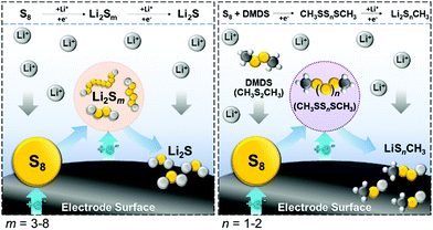 | ||
| Fig. 13 Schematic showing the mediated discharge mechanism when using a DMDS-containing electrolyte (right) vs. a conventional electrolyte (left). | ||
Bai, Lu and co-workers recently reported the in situ generation of homogeneous RMs from solid state additives to Li–S cells.46 The introduction of soluble RMs into discharged Li–S cells can cause unwanted side-reactions unless the batteries are immediately charged after construction. Lithium thiophosphate (LPS) has been explored previously as a solid electrolyte in Li–S batteries due to its high conductivity, however its wider application has been frustrated by its redox activity and chemical stability at potentials similar to Li2S. The authors proposed that such redox activity might be exploited for the in situ generation of RMs able to oxidise Li2S. Positive electrodes were constructed from a blend of commercial micron-sized Li2S powder and LPS (0, 1 and 10 wt%) on carbon. Charging the battery with 10% LPS at C/20 showed that the charging voltage dramatically decreased, where there is initially a small double-activation peak at ∼2.65 V vs. Li+/Li corresponding to the oxidation of LPS (switching-on) and activation of Li2S, followed by sloping charge curves beginning at ∼2.8 V, (cf. typical Li2S activation peaks approach 4.0 V). The proposed mechanism, as indicated by a combination of EIS, XANES and Raman spectroscopy, suggests that the LPS particles are initially delithiated (switched-on) to produce soluble phosphosulfide anions which then migrate to the crystalline Li2S and react to form new polysulfide species (a double activation process). The phosphorus atom from the LPS is further able to bond with and stabilise the polysulfides. Once charged, the polysulfides detach from the LPS species to form S8, regenerating the RM so that it acts in a truly catalytic manner. Operational challenges remain, however. Improved charge overpotentials and cycling stability is reduced at lower electrolyte ratios, and very low current densities (C/40) are required to achieve full discharge. Nonetheless, the stable capacity of >400 mA h gLi2S−1 obtained with cells at extremely high mass loadings (70% commercial Li2S) and low electrolyte ratios (4 μL mgLi2S−1) are encouraging for the development of inorganic sulfide RMs in Li–S batteries.
The application of RAMs in Li–S batteries is a relatively new area of study but one that contains a great deal of promise. Li–S cell chemistry is complex and a key requirement will be the continued development of our understanding of the fundamental speciation and redox mechanisms in the cell, including the rate limiting steps of both charge and discharge processes, and the equilibria between various solid and dissolved components. RAMs have a role to play across all of these areas but joined-up thinking is required, where mediator design needs to take account of both charge and discharge processes (rather than focusing solely on one or the other). Mediator design considerations will also differ depending on the target application (optimising for high-energy or high-rate), and new studies which account for interplay between RAMs and various cell components – including the electrolyte, solvent and electrode – will help to target and refine the application of mediators in next-generation systems. As the field develops, it is also important to note that current Li–S cells are often poorly optimised for use with RAMs, and there are undoubtedly new opportunities for innovation in cell-design and chemistry which could help to unlock much lower electrolyte/sulfur ratios and greatly improved charging rates.
Redox flow batteries
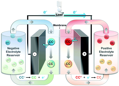
In contrast to the batteries described above, RFBs typically employ RAMs as their primary charge carriers (CC, see Fig. 2c), making them especially and uniquely critical to the performance of this battery type.1,2,17 A typical RFB cell is shown in Fig. 14, where dissolved CCs are stored in external reservoirs and pumped through an electrochemical cell to charge and discharge the battery as required. These positive and negative electrolytes (sometimes referred to as the catholyte/posolyte and anolyte/negolyte, respectively) are separated in the cell by a porous separator or ion-conducting membrane, permitting exchange of charge-balancing electrolyte ions between the cell compartments. The use of RAMs as the energy storage mechanism in RFBs decouples capacity (via the total reservoir volume) from power (via the size of the current collectors and cell design), rendering the batteries easily scaled and potentially more economically viable for grid-scale applications.23,47Historically, RFBs have relied on ionic CCs based on iron, chromium, zinc, or cerium, dissolved in aqueous electrolytes.17 Today, the most commercially advanced system is the all-vanadium-RFB developed by Skyllas–Kazacos and colleagues in the late 1980s.11,17 The system exploits the multiple stable oxidation states of vanadium sulfate, (cycling between V5+/V4+ in the positive electrolyte and V2+/V3+ in the negative electrolyte), yielding a cell voltage (Vcell) of 1.26 V and energy density of 20–35 W h dm−3.2 Cost and lifespan are the primary considerations when developing RFBs and, though the vanadium-RFB was expected to be highly competitive, particularly thanks to its very high cycle lifetime, total device cost has remained high at ca. $500–600 per kW h, while manufacturing and performance improvements in LIBs have dramatically reduced their cost to <$200 per kW h.1 Specifically, vanadium RFBs have struggled to compete due to the high and fluctuating price of vanadium which is strongly linked to the steel industry.17 As such, despite their advantages (particularly in larger stationary storage applications), further market penetration rests heavily on the discovery of low cost, abundant CCs and this has fuelled a recent surge in research.23
In developing new CCs for use in RFBs there are several properties to consider. The energy density of the cell depends heavily on the maximum concentration of CC (C), the potential difference between redox couples (Vcell), and the number of electrons involved in the redox reaction (n) as shown in eqn (4):
 | (4) |
In addition to the properties outlined above, fast electron and mass transfer are also key to enabling high power density. Slow rates of electron transfer contribute to large overpotentials during cycling and reduced energy efficiency. Of course, the CC itself must be stable in both its reduced and oxidised states to retain capacity over many cycles. In addition, electrolyte viscosity should be minimised to reduce the energy required to pump electrolyte from its storage reservoir and through the electrochemical cell. During charging and discharging of asymmetric systems (i.e. a RFB containing different CCs in the positive and negative electrolyte), poor membrane selectivity can allow cross-over of CCs, leading to self-discharge and permanent capacity loss.1,17 Symmetric systems, employing the same CC at both electrodes, but operating in different redox states, partially mitigate this degradation process as the full capacity can be regenerated in the subsequent charge cycle.
Given all of the factors discussed above, renewed interest in RFBs has driven a broad search for new CCs across a wide range of molecular species, and recent studies have included the exploration of metal ions,2,11 clusters,48,49 metallocenes,50,51 organic molecules,52–54 and polymeric species.1,55 In the following we will examine the molecular engineering approaches that have been applied to develop CCs with improved properties and thereby enhanced RFB performance.
Metal-centred charge carriers
As in both Li–air and Li–S batteries, organometallic and cluster-based CCs offer tuneable redox chemistries and solubilities, alongside good electrochemical stability, making them ideal candidates as electrolyte species in RFBs. Metallocenes, in particular, have been shown to offer the advantage of fast electron transfer kinetics,50 a key property in enabling high power density devices.Yu and co-workers demonstrated a non-aqueous all-metallocene RFB in which ferrocene and cobaltocene were used as the positive and negative electrolyte respectively.50 The redox potential of both metallocenes is highly solvent dependant, therefore ferrocene in N,N-dimethylformamide (DMF) was chosen as the positive electrolyte and cobaltocene in DOL as negative electrolyte, producing a Vcell of 1.7 V. The proof-of-concept flow cell achieved coulombic and energy efficiencies of ∼95% and ∼85%, respectively, while electron transfer rate constants were approximately one order of magnitude faster than conventional vanadium sulfates. Further optimisation was achieved by methylating the cobaltocene, tuning the redox potential by −400 mV to produce a Vcell of 2.1 V when paired with ferrocene as the positive electrolyte. Oh and co-workers similarly demonstrated acetylation of the cyclopentadienyl ring in ferrocene resulted in a +200 mV shift in redox potential, in addition to achieving a four-fold increase in solubility (in 1 M LiPF6 in propylene carbonate).51 This example neatly encapsulates how even simple functionalisation or molecular-design approaches can lead to dramatically improved performance in RFBs (in this case, improving both C and Vcell, as relates to energy density in eqn (4) above).
One particularly interesting strategy was recently reported by Marshak and co-workers who demonstrated an aqueous RFB with Vcell of 2.1 V (far in excess of the thermodynamic potential of water electrolysis (1.23 V)).56 The researchers suppressed catalysis of hydrogen evolution by the negative electrolyte by using a strongly chelating ligand (1,3-propylenediaminetertaacetic acid (PDTA)) to prevent coordination of water to the metal ion. The chromium-PDTA complex used as a negative electrolyte by the authors has solubility >1 M at pH 9 and a highly negative reduction potential of −1.31 V vs. Ag/AgCl in water. The Cr-PDTA complex also demonstrated very high coulombic efficiency when coupled with Fe(CN)64−/Fe(CN)63− and Br2/Br− positive electrolytes and achieved extraordinary Vcell values for an aqueous system. The demonstration of this unique kinetic stabilisation strategy to circumvent the ubiquitous problem of water electrolysis in aqueous RFBs, whilst using highly abundant, cost-effective electrolytes, is particularly noteworthy.
POMs have also been investigated as new CCs due to their fast, reversible multi-electron redox reactions. Unlike their use as RMs in Li–air cells (discussed above) where they only need transfer 1–2 electrons to mediate cell chemistry,34,57 their ability to act as remarkable electron sponges has set them apart as highly attractive candidates for use in RFBs (not to mention their extraordinarily wide and freely tuneable range of redox potentials and solubilities). An excellent example of this was reported by Symes, Cronin and co-workers who employed the Wells–Dawson-type phosphotungstate, [P2W18O62]6−, as the negative CC in an aqueous asymmetric RFB.48 They found that the redox properties of [P2W18O62]6− are highly dependent on both pH and concentration, showing that at pH 4 and concentrations >100 mM, the CC is capable of reversibly exchanging as many as 18 electrons at potentials within the electrochemical stability window of water. The performance of Li6[P2W18O62] was investigated in a proof-of-concept RFB with a Br2/HBr positive electrolyte. An average Vcell of 1.25 V and a practical energy density of 225 W h dm−3 on discharge was achieved at POM concentrations of 0.5 M. When extrapolated to the maximum solubility of Li6[P2W18O62] in water (1.9 M), the authors calculate that this would result in a truly remarkable theoretical energy density of more than 1000 W h dm−3 (well over 25 times that of the commercialised vanadium-RFB).
In the absence of targeted molecular design, the solubility of POMs in non-aqueous solvent is typically low, however, Matson and co-workers investigated polyoxovanadate alkoxide clusters, [V6O7(OR)12] (where R = OCH3, OCH2CH3), as CCs in non-aqueous RFBs.49 These materials display four one-electron redox couples over a potential range of ∼2 V such that during charging in a symmetric system, the polyalkoxovanadate undergoes a two-electron reduction at the negative electrode concurrently with a two-electron oxidation at the positive electrode. To further enhance energy density, the solubility of the polyalkoxovanadate was increased by replacing several surface alkoxy groups with ethers. Clusters with mixed ether/alkoxy group surface functionalisation displayed improved solubility (up to 1.2 M in 0.1 M [TBA][PF6] in acetonitrile). While the increased solubility in organic solvent and multi-electron redox chemistry is promising for enhanced energy density, preliminary testing of the functionalised polyoxovanadate clusters in a RFB showed steady capacity fade. Cyclic voltammetry of electrolytes following 30 cycles in a RFB indicated partial degradation of the polyoxovanadate clusters.
Organic charge carriers
Unlike RAMs employed as mediators in Li–air and Li–S batteries (which are typically used sparingly or even in catalytic quantities), RAMs employed as CCs are a major component of RFBs and, as such, finding species which have attractive and tuneable properties whilst being (relatively) low cost and highly abundant is of paramount importance. As a result, there is a growing interest in the development of organic CCs as alternatives to metal-centred species. Organic CCs investigated to date include nitroxide radicals such as TEMPO,55,58 carbonyls such as fluorenone and benzophenone,53 heterocyclic aromatics such as viologens,55 and phenothiazine,59 and dialkoxybenzenes,53 to name just a few. Here we examine a selection of the approaches that have been adopted in order to optimise the solubility, stability, and redox properties of these CCs for use in RFBs.Aziz and co-workers have previously investigated a series of tuneable anthraquinones as CCs in the negative electrolyte of asymmetric organic–inorganic aqueous RFBs.54 The characteristic two-electron redox reactivity, stability, low material cost and easy functionalisation of quinones makes them particularly promising components in organic RFBs. Recently, the same group developed a novel in situ electrosynthetic approach to prepare 3,3′-(9,10-anthraquinone-diyl)bis(3-methylbutanoic acid) (DPivOHAQ) and 4,4′-(9,10-anthraquinone-diyl)dibutanoic acid (DBAQ).60 Paired with a ferrocyanide positive electrolyte, these negative electrolytes demonstrate extremely good stability and a Vcell of 1.0 V. In particular, modifying the structure of the CC so that the functional groups are linked to the anthraquinone core via covalent C–C made the CCs significantly more resistant to nucleophilic attack than previously investigated C–O linked analogues. A minimal amount of capacity fade could be attributed to the disproportionation reaction of reduced anthraquinone to anthrone, though this was shown to be suppressed by increasing the pH. Moreover, exposure of negative electrolyte to air was shown to re-oxidise anthrone to anthroquinone allowing lost capacity to be easily regenerated. As such, the DPivOHAQ/ferrocyanide flow cell demonstrated an extremely low capacity fade of <1% per year at pH 14 – a compelling demonstration of the effectiveness of targeted molecular design when coupled to intimate understanding of the specific chemistry of a chosen RAM.
High throughput computational screening methods have also been used to assess the structure–property relationship of quinones and their derivatives.52 Careful molecular design of quinones for application as positive electrolyte is required to achieve sufficiently positive redox potentials and electrochemical stability. Janek, Schröder and co-workers investigated how the electron density, and therefore redox potential of the molecule is tuned by altering the quinone framework. Incorporation of nitrogen in the aromatic ring of naphthaquinones, resulted in a 342 mV positive shift in redox potential of dihydroxyphthalazine (DHP) compared to 1,4-hydronaphthoquinone. The electrochemical properties of DHP and two derivatives, 5,8-dihydroxy-6-methoxy-2,3-phthalazine (DHP(MeO)) and 5,8-dihydroxy-6,7-dimethyl-2,3-phthalazine (DHP(Me)2) (Fig. 15) were investigated as potential positive electrolytes for aqueous RFBs. DHP(Me)2 was selected to stabilise the CC against nucleophilic attack at the quinone aromatic ring. This had the desired effect of inhibiting decomposition via Michael addition and significantly improved capacity retention upon cycling.
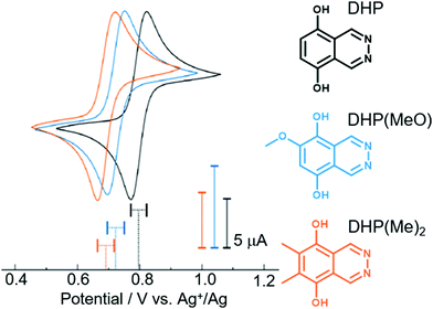 | ||
| Fig. 15 Cyclic voltammograms of dihydroxyphthalazine and derivatives in 1 M H2SO4 electrolyte at a glassy carbon working electrode at a scan rate of 10 mV s−1. Adapted with permission from ref. 52. Copyright 2020 American Chemical Society. | ||
Phenothiazines have previously been investigated as CCs to prevent over-charging in Li-ion batteries. Brushett, Odom and co-workers explored the molecular functionalisation of N-ethylphenothiazine (EPT) to tailor its solubility and redox properties for application in non-aqueous RFBs.59 EPT shows two reversible one-electron redox processes separated by ∼0.6 V (Fig. 16a) and is therefore suitable as a CC for symmetric RFBs (albeit with small Vcell). The group explored the functionalisation of EPT with methoxy and oligo(glycol) groups on the nitrogen, 3 and 7 positions in order to improve solubility and stability. The neutral molecule, N-ethyl-3,7-bis(2-(2-methoxyethoxy)ethoxy)phenothiazine (B(MEEO)EPT), is a liquid at room temperature and miscible with acetonitrile, however, the mono- and di-cationic forms have a maximum solubility of just ∼0.5 M in 0.5 M [TEA][TFSI] in acetonitrile. Compared to native EPT, which has a maximum solubility of 0.1 M under the same conditions, this still marks a significant improvement in solubility achieved through systematic molecular design. However, (B(MEEO)EPT) was cycled in a 0.3 M proof-of-concept symmetric RFB and showed 27% capacity fade over 460 hours, attributed to undesirable cross-over of the CCs through the microporous separator (Fig. 16b).
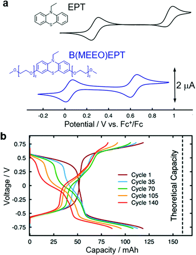 | ||
| Fig. 16 (a) Cyclic voltammograms of phenothiazine derivatives EPT and B(MEEO)EPT measured at 1 mM concentration in 0.5 M [TEA][TFSI] in acetonitrile at a glassy carbon working electrode at a scan rate of 10 mV s−1, referenced to ferrocenium/ferrocene (Fc+/Fc). (b) Cycling profiles of B(MEEO)EPT in a 0.3 M symmetric flow cell at constant current of ±25 mA cm−2 and potential cut offs of ±0.775 V. Adapted with permission from ref. 59. Copyright 2019 American Chemical Society. | ||
Benzophenones can be reduced at relatively negative potentials and are therefore primarily under investigation as CCs in negative electrolytes. Lemmon and co-workers reported an all-organic, asymmetric, non-aqueous RFB with a large Vcell of almost 3 V.53 The negative electrolyte containing 2-methylbenzophenone undergoes a reversible one-electron reduction from the carbonyl to the radical anion at the highly negative potential of −2.26 V vs. Ag+/Ag. Introduction of the methyl group in the 2-position of benzophenone resulted in a liquid redox species with a remarkably high solubility of 5.6 M in acetonitrile. By pairing this with a common positive electrolyte, 2,5-di-tert-butyl-1-methoxy-4-[2′-methoxyethoxy]benzene (DBMMB), a Vcell of 2.97 V was achieved. The high solubility of the CCs and large Vcell resulted in a RFB with a high theoretical energy density of 233 W h dm−3 and a proof-of-concept RFB using 0.1 M CC showed a coulombic efficiency of 95% and an energy efficiency of ∼70% over 50 cycles.
Sanford and co-workers have recently demonstrated an all-organic non-aqueous RFB with a remarkable Vcell of 3.2 V.61 A series of substituted cyclopropenium (CP) CCs were designed using a joint computational/synthetic strategy which targeted the design of stable, extremely high potential positive electrolytes. Computational and mechanistic analysis led to the synthesis of a butylthioether-substituted cyclopropenium species with an oxidation occurring at +1.40 V vs. Fc/Fc+ (a 480 mV positive shift compared to cyclopropenium alone, attributed to the more weakly π-donating nature of the sulfur substituent in the cyclic core). Despite its impressive redox potential, upon oxidation the thioether species was subsequently shown to undergo decomposition via C–S bond cleavage. Exploiting a good understanding of the decay mechanism allowed the authors to design of a more stable methylthioether-substituted analogue. To maximise Vcell, a CC with low reduction potential (N-alkylphthalimide) was employed as the negative electrolyte in a proof-of-concept asymmetric flow cell. Although rapid capacity fade was observed after 17 cycles, post-cycling analysis attributed this to degradation of the phthalimide-based negative electrolyte while the methylthioether-cyclopropenium CC was shown to have retained > 90% of its capacity.
Cross-over mitigation strategies
One feature RFBs share in common with Li–S batteries is the need for membrane separators with high ionic-conductivity, selectivity and stability. These are critical to device performance (capacity retention in particular), where the membrane should allow free transport of the supporting electrolyte ions necessary to maintain charge neutrality and meet power density requirements, whilst preventing cross-over of CCs to the opposite half-cell (leading to temporary capacity fade in symmetric RFBs and permanent capacity loss in asymmetric cells). Typically, commercial ion-exchange membranes such as the proton exchange fluoropolymer, Nafion® are used to separate electrolytes based on their charge, though they are often expensive, accounting for a large fraction of the cell cost.55 An alternative strategy is to separate electrolyte species based on their size using porous separators (such as water treatment or dialysis membranes).1 Ensuring high selectivity with these membranes requires especially bulky CCs such as polymeric redox species or larger nanoscale molecular species, such as POMs (discussed above).A strategy to design polymeric CCs for application in aqueous RFBs was demonstrated by Schubert and co-workers, who designed a system specifically to allow for the use of inexpensive size-exclusion membranes.55 The CCs comprise a redox-active component coupled to a polymer backbone also functionalised with a quaternary ammonium moiety to enhance water solubility. The positive electrolyte material used TEMPO as the redox species, whilst the negative electrolyte uses a viologen moiety. A secondary advantage is that NaCl could be used as the supporting electrolyte, avoiding the use of the corrosive acids common in aqueous RFBs. The authors found that their commercially available size-exclusion membrane had comparable ionic conductivity to Nafion, whilst showing enhanced selectivity. The polymer was specifically designed to enhance selectivity whilst keeping viscosity as low as possible to minimise the energy required to pump electrolyte by tuning its molecular weight. Over 10![[thin space (1/6-em)]](https://www.rsc.org/images/entities/char_2009.gif) 000 charge–discharge cycles a coulombic efficiency of 99% was observed, though the proof-of-concept RFB had low energy density and was susceptible to capacity fade between cycles due to side reactions through the viologen radical cation.
000 charge–discharge cycles a coulombic efficiency of 99% was observed, though the proof-of-concept RFB had low energy density and was susceptible to capacity fade between cycles due to side reactions through the viologen radical cation.
As already alluded to, one alternative strategy to minimise the detrimental effects of membrane cross-over is to design symmetric RFB systems in which a single CC is used in both the positive and negative electrolyte. This requires CCs with redox processes at both high and low potentials to maximise Vcell. Schubert and co-workers, demonstrated the first example of this by tethering TEMPO and phenazine moieties to a single molecule (note that two TEMPO groups were required per phenazine in order to fully balance its two-electron redox chemistry).58 Both redox groups were covalently bonded via a water-soluble triethylene glycol linker, yielding a single CC with a theoretical Vcell of 1.2 V. Electrochemical characterisation revealed the reversible oxidation of the TEMPO sites at 0.6 V vs. Ag+/Ag while, in contrast, reduction of phenazine at −0.6 V showed sluggish electron-transfer kinetics. Coulombic efficiency >98% and good capacity retention was achieved over 2000 cycles in a prototype symmetric aqueous RFB. The low voltage efficiency and electrochemical yield (% of theoretical capacity achieved during charge) was attributed to the slow electron-transfer kinetics of phenazine.
RAMs are intrinsically linked to the performance of RFBs, where their physicochemical properties often directly set the boundaries for cell performance in a way which is not mirrored in the Li–air and Li–S systems described above. Recent years have seen a great deal of innovation in this space, and development of both inorganic (or metal-centred) and organic redox species continues to drive performance gains in both aqueous and non-aqueous batteries. On a surface level, optimisation is a simpler task than that required in other battery technologies, where a focus on maximising the redox potential, solubility and stability of the RAM(s) (without the requirement to consider interactions or reactivity with another substrate) is all that is required. This simplification overlooks, however, the fact that in order to solve arguably the most important technological challenge in RFBs – achieving very high long term cycling stability (e.g. capacity loss of <1% per year) – developing a fundamental understanding of the interplay between the RAM and the electrode, electrolyte, solvent and even membrane/separator will be just as crucial as in the other emerging technologies described above. Increased use of modelling and data-driven design strategies – some key examples of which are described above – is expected to be an especially powerful tool here, and will require collaborative approaches making the most of researchers working across a number of fields. We also expect that, as research into other ‘beyond Li-ion’ battery technologies continues to mature, the delineation between these systems and RFBs will continue to blur, providing exciting new opportunities (e.g. in ‘hybrid-RFBs’, such as the Li–S RFB described on page 12 (see Fig. 12) above).
Conclusions and outlook
In this Tutorial Review, we have highlighted emergent battery technologies that potentially offer paradigm-shifting performances in terms of their specific energies (Li–air and Li–S) and scalability/lifetime (redox flow). One of the major differences between each of these technologies and “conventional” battery systems in terms of operating principles and performance is that they generally rely more on solution-phase reactions, than on solid-state chemistry. The oxygen redox reactions that make Li–air batteries the most promising of all “beyond Li-ion” batteries in terms of their specific energies are also their biggest hurdle. The Li–S battery, on the other hand, is poised to make the leap to commercial production, but state-of-the-art cells experience drops in capacity at high rates and limited cycle life, due to the involvement of dissolved intermediates during discharge. Redox mediators can alleviate these problems to an extent, extending the cycle life of Li–air cells and increasing the capacity of Li–S cells. However, the existing crop of mediators can degrade during operation and the development of new mediators is hindered by a lack of a detailed understanding of their modes of operation. Redox-active molecules in redox-flow batteries play different roles to those in Li–air and Li–S cells, but the challenges are often the same – maintaining chemical and electrochemical stability under the operating conditions of the cells – and relatively few mediators offer the performance needed for widespread adoption. Critically, any molecular charge carrier designed for use in flow batteries must also meet strict scalability and cost targets.Regardless of the targeted battery technology, the development of new redox-active mediators – and advances in this area – require the optimisation of several factors in tandem. The chemical structures of mediators must be tuned to make them soluble to high concentrations, chemically and electrochemically stable, and involatile. We propose that such synthetic challenges may be considered “routine” by some of our colleagues within the synthetic-chemistry community, but not necessarily so by those of us in the battery and electrochemistry communities. We believe that true progress in this area can only come about by collaborations between those of us in the electrochemistry, materials, and battery communities and our colleagues in the synthetic-chemistry community. It may be that a sizeable proportion of synthetic chemists are unaware that their skills and knowledge be put to good use in battery science. It may even be that some are reticent to get involved in the “black art” of electrochemistry. In this respect, we offer up redox-flow batteries as a possible route into battery science as the challenges are arguable less daunting; i.e. prima facie, the redox species in RFBs must only be made soluble to high concentrations and their redox levels tuned to specific values. If we can work together with synthetic chemists to solve the problems facing redox-flow batteries, perhaps we can also convince them to put their skills to use in solving the problems facing other next-generation battery technologies. The concepts and devices may feel less familiar, but the challenges are in many ways the same and cannot be solved by operating in silos. To the intrepid researcher, we offer up Fig. 17 as a guide and conclude with a call-to-arms to chemists of all stripes – battery science needs you!
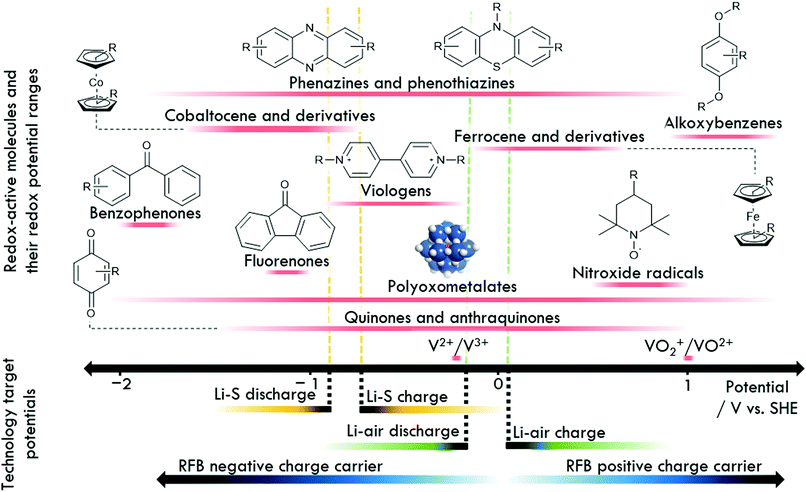 | ||
| Fig. 17 Schematic overview providing a ‘potential map’ of selected RAMs prevalent in next-generation batteries, and their redox potentials referenced verses the standard hydrogen electrode (SHE). | ||
Author contributions
CH, AJK and CLP collated the literature and wrote the manuscript. JMC, DAW, GNN and LRJ conceptualised the study and wrote the manuscript.Conflicts of interest
There are no conflicts to declare.Acknowledgements
The authors gratefully acknowledge the support of The Faraday Institution's LiSTAR project (EP/S003053/, FIRG014). CLP thanks the EPSRC for funding through the Centre for Doctoral Training in Sustainable Chemistry (EP/L015633/1). JMC and GNN thank the Leverhulme Trust (RPG-2016-442) and JMC, DAW and GNN thank CAM-IES for support. LRJ gratefully acknowledges support from the EPSRC (EP/S001611/1). All of the authors thank the University of Nottingham's Propulsion Futures Beacon of Excellence for supporting this research.Notes and references
- L. Trahey, F. R. Brushett, N. P. Balsara, G. Ceder, L. Cheng, Y.-M. Chiang, N. T. Hahn, B. J. Ingram, S. D. Minteer, J. S. Moore, K. T. Mueller, L. F. Nazar, K. A. Persson, D. J. Siegel, K. Xu, K. R. Zavadil, V. Srinivasan and G. W. Crabtree, Proc. Natl. Acad. Sci. U. S. A., 2020, 117, 12550 CrossRef CAS , and references contained therein.
- T. M. Gür, Energy Environ. Sci., 2018, 11, 2696–2767 RSC.
- M. Li, J. Lu, Z. Chen and K. Amine, Adv. Mater., 2018, 30, 1800561 CrossRef PubMed , and references contained therein.
- M. Winter, B. Barnett and K. Xu, Chem. Rev., 2018, 118, 11433–11456 CrossRef CAS PubMed , and references contained therein.
- G. Zubi, R. Dufo-López, M. Carvalho and G. Pasaoglu, Renewable Sustainable Energy Rev., 2018, 89, 292–308 CrossRef , and references contained therein.
- J. Betz, G. Bieker, P. Meister, T. Placke, M. Winter and R. Schmuch, Adv. Energy Mater., 2019, 9, 1803170 CrossRef.
- J. Biemolt, P. Jungbacker, T. van Teijlingen, N. Yan and G. Rothenberg, Materials, 2020, 13, 425 CrossRef CAS PubMed , and references contained therein.
- W.-J. Kwak, Rosy, D. Sharon, C. Xia, H. Kim, L. R. Johnson, P. G. Bruce, L. F. Nazar, Y.-K. Sun, A. A. Frimer, M. Noked, S. A. Freunberger and D. Aurbach, Chem. Rev., 2020, 120, 6626–6683 CrossRef CAS PubMed , and references contained therein.
- A. Manthiram, Y. Fu, S.-H. Chung, C. Zu and Y.-S. Su, Chem. Rev., 2014, 114, 11751–11787 CrossRef CAS PubMed , and references contained therein.
- Z. Yang, J. Zhang, M. C. W. Kintner-Meyer, X. Lu, D. Choi, J. P. Lemmon and J. Liu, Chem. Rev., 2011, 111, 3577–3613 CrossRef CAS PubMed , and references contained therein.
- Á. Cunha, J. Martins, N. Rodrigues and F. P. Brito, Int. J. Energy Res., 2015, 39, 889–918 CrossRef.
- D. Eroglu, K. R. Zavadil and K. G. Gallagher, J. Electrochem. Soc., 2015, 162, A982–A990 CrossRef CAS.
- Z. Li, M. S. Pan, L. Su, P.-C. Tsai, A. F. Badel, J. M. Valle, S. L. Eiler, K. Xiang, F. R. Brushett and Y.-M. Chiang, Joule, 2017, 1, 306–327 CrossRef CAS.
- The Faraday Institution Reports: High-energy Battery Technologies, https://faraday.ac.uk/wp-content/uploads/2020/01/High-Energy-battery-technologies-FINAL.pdf, accessed November 2020.
- M. S. Ziegler, J. M. Mueller, G. D. Pereira, J. Song, M. Ferrara, Y.-M. Chiang and J. E. Trancik, Joule, 2019, 3, 2134–2153 CrossRef.
- K. B. Hueso, M. Armand and T. Rojo, Energy Environ. Sci., 2013, 6, 734–749 RSC.
- J. Winsberg, T. Hagemann, T. Janoschka, M. D. Hager and U. S. Schubert, Angew. Chem., Int. Ed., 2017, 56, 686–711 CrossRef CAS PubMed , and references contained therein.
- E. Peled and S. Menkin, J. Electrochem. Soc., 2017, 164, A1703–A1719 CrossRef CAS.
- Y. Song, W. Cai, L. Kong, J. Cai, Q. Zhang and J. Sun, Adv. Energy Mater., 2020, 10, 1901075 CrossRef CAS , and references contained therein.
- J.-B. Park, S. H. Lee, H.-G. Jung, D. Aurbach and Y.-K. Sun, Adv. Mater., 2018, 30, 1704162 CrossRef PubMed , and references contained therein.
- I. Landa-Medrano, I. Lozano, N. Ortiz-Vitoriano, I. Ruiz de Larramendi and T. Rojo, J. Mater. Chem. A, 2019, 7, 8746–8764 RSC , and references contained therein.
- L. Trahey, F. R. Brushett, N. P. Balsara, G. Ceder, L. Cheng, Y.-M. Chiang, N. T. Hahn, B. J. Ingram, S. D. Minteer, J. S. Moore, K. T. Mueller, L. F. Nazar, K. A. Persson, D. J. Siegel, K. Xu, K. R. Zavadil, V. Srinivasan and G. W. Crabtree, Proc. Natl. Acad. Sci. U. S. A., 2020, 117, 12550 CrossRef CAS PubMed.
- R. Dmello, J. D. Milshtein, F. R. Brushett and K. C. Smith, J. Power Sources, 2016, 330, 261–272 CrossRef CAS.
- C. Zhang, N. Dandu, S. Rastegar, S. N. Misal, Z. Hemmat, A. T. Ngo, L. A. Curtiss and A. Salehi-Khojin, Adv. Energy Mater., 2020, 2000201, 1–9 Search PubMed.
- A. Halder, H.-H. Wang, K. C. Lau, R. S. Assary, J. Lu, S. Vajda, K. Amine and L. A. Curtiss, ACS Energy Lett., 2018, 3, 1105–1109 CrossRef CAS.
- J. Lu, Y. Jung Lee, X. Luo, K. Chun Lau, M. Asadi, H.-H. Wang, S. Brombosz, J. Wen, D. Zhai, Z. Chen, D. J. Miller, Y. Sub Jeong, J.-B. Park, Z. Zak Fang, B. Kumar, A. Salehi-Khojin, Y.-K. Sun, L. A. Curtiss and K. Amine, Nature, 2016, 529, 377–382 CrossRef CAS PubMed.
- Y. Chen, X. Gao, L. R. Johnson and P. G. Bruce, Nat. Commun., 2018, 9, 767 CrossRef PubMed.
- X. Gao, Y. Chen, L. Johnson and P. G. Bruce, Nat. Mater., 2016, 15, 882–888 CrossRef CAS PubMed.
- X. Gao, Y. Chen, L. R. Johnson, Z. P. Jovanov and P. G. Bruce, Nat. Energy, 2017, 2, 17118 CrossRef CAS.
- B. J. Bergner, A. Schurmann, K. Peppler, A. Garsuch and J. Janek, J. Am. Chem. Soc., 2014, 136, 15054–15064 CrossRef CAS PubMed.
- Y. Chen, S. A. Freunberger, Z. Peng, O. Fontaine and P. G. Bruce, Nat. Chem., 2013, 5, 489–494 CrossRef CAS PubMed.
- L. Yang, J. T. Frith, N. Garcia-Araez and J. R. Owen, Chem. Commun., 2015, 51, 1705–1708 RSC.
- D. Sun, Y. Shen, W. Zhang, L. Yu, Z. Yi, W. Yin, D. Wang, Y. Huang, J. Wang, D. Wang and J. B. Goodenough, J. Am. Chem. Soc., 2014, 136, 8941–8946 CrossRef CAS PubMed.
- T. Homewood, J. T. Frith, J. P. Vivek, N. Casañ-Pastor, D. Tonti, J. R. Owen and N. Garcia-Araez, Chem. Commun., 2018, 54, 9599–9602 RSC.
- D. Kundu, R. Black, B. Adams and L. F. Nazar, ACS Cent. Sci., 2015, 1, 510–515 CrossRef CAS PubMed.
- K. P. C. Yao, J. T. Frith, S. Y. Sayed, F. Bardé, J. R. Owen, Y. Shao-Horn and N. Garcia-Araez, J. Phys. Chem. C, 2016, 120, 16290–16297 CrossRef CAS.
- B. D. Adams, E. V. Carino, J. G. Connell, K. S. Han, R. Cao, J. Chen, J. Zheng, Q. Li, K. T. Mueller, W. A. Henderson and J.-G. Zhang, Nano Energy, 2017, 40, 607–617 CrossRef CAS.
- S. Meini, R. Elazari, A. Rosenman, A. Garsuch and D. Aurbach, J. Phys. Chem. Lett., 2014, 5, 915–918 CrossRef CAS PubMed.
- K. R. Kim, K.-S. Lee, C.-Y. Ahn, S.-H. Yu and Y.-E. Sung, Sci. Rep., 2016, 6, 32433 CrossRef CAS PubMed.
- J. Li, L. Yang, S. Yang and J. Y. Lee, Adv. Energy Mater., 2015, 5, 1501808 CrossRef.
- L. C. H. Gerber, P. D. Frischmann, F. Y. Fan, S. E. Doris, X. Qu, A. M. Scheuermann, K. Persson, Y.-M. Chiang and B. A. Helms, Nano Lett., 2016, 16, 549–554 CrossRef CAS PubMed.
- J. Li, L. Yang, B. Yuan, G. Li and J. Y. Lee, Mater. Today Energy, 2017, 5, 15–21 CrossRef.
- Y. Tsao, M. Lee, E. C. Miller, G. Gao, J. Park, S. Chen, T. Katsumata, H. Tran, L.-W. Wang, M. F. Toney, Y. Cui and Z. Bao, Joule, 2019, 3, 872–884 CrossRef CAS.
- S. Chen, F. Dai, M. L. Gordin, Z. Yu, Y. Gao, J. Song and D. Wang, Angew. Chem., Int. Ed., 2016, 55, 4231–4235 CrossRef CAS PubMed.
- S. Chen, Y. Gao, Z. Yu, M. L. Gordin, J. Song and D. Wang, Nano Energy, 2017, 31, 418–423 CrossRef CAS.
- M. Li, Z. Bai, Y. Li, L. Ma, A. Dai, X. Wang, D. Luo, T. Wu, P. Liu, L. Yang, K. Amine, Z. Chen and J. Lu, Nat. Commun., 2019, 10 CrossRef PubMed.
- R. M. Darling, K. G. Gallagher, J. A. Kowalski, S. Ha and F. R. Brushett, Energy Environ. Sci., 2014, 7, 3459–3477 RSC.
- J. J. Chen, M. D. Symes and L. Cronin, Nat. Chem., 2018, 10, 1042–1047 CrossRef CAS PubMed.
- L. E. Vangelder, H. D. Pratt, T. M. Anderson and E. M. Matson, Chem. Commun., 2019, 55, 12247–12250 RSC.
- Y. Ding, Y. Zhao, Y. Li, J. B. Goodenough and G. Yu, Energy Environ. Sci., 2017, 10, 491–497 RSC.
- H. S. Kim, T. Yoon, Y. Kim, S. Hwang, J. H. Ryu and S. M. Oh, Electrochem. Commun., 2016, 69, 72–75 CrossRef CAS.
- J. D. Hofmann, S. Schmalisch, S. Schwan, L. Hong, H. A. Wegner, D. Mollenhauer, J. Janek and D. Schröder, Chem. Mater., 2020, 32, 3427–3438 CrossRef CAS.
- X. Xing, Q. Liu, W. Xu, W. Liang, J. Liu, B. Wang and J. P. Lemmon, ACS Appl. Energy Mater., 2019, 2, 2364–2369 CrossRef CAS.
- B. Huskinson, M. P. Marshak, C. Suh, S. Er, M. R. Gerhardt, C. J. Galvin, X. Chen, A. Aspuru-Guzik, R. G. Gordon and M. J. Aziz, Nature, 2014, 505, 195–198 CrossRef CAS PubMed.
- T. Janoschka, N. Martin, U. Martin, C. Friebe, S. Morgenstern, H. Hiller, M. D. Hager and U. S. Schubert, Nature, 2015, 527, 78–81 CrossRef CAS PubMed.
- B. H. Robb, J. M. Farrell and M. P. Marshak, Joule, 2019, 3, 2503–2512 CrossRef CAS.
- W. Choi, D. Im, M. S. Park, Y.-G. Ryu, S. S. Hwang, Y. S. Kim, H. Kim, S.-G. Doo and H. Chang, Electrochem., 2016, 84, 882–886 CrossRef CAS.
- J. Winsberg, C. Stolze, S. Muench, F. Liedl, M. D. Hager and U. S. Schubert, ACS Energy Lett., 2016, 1, 976–980 CrossRef CAS.
- N. H. Attanayake, J. A. Kowalski, K. V. Greco, M. D. Casselman, J. D. Milshtein, S. J. Chapman, S. R. Parkin, F. R. Brushett and S. A. Odom, Chem. Mater., 2019, 31, 4353–4363 CrossRef CAS.
- M. Wu, Y. Jing, A. A. Wong, E. M. Fell, S. Jin, Z. Tang, R. G. Gordon and M. J. Aziz, Chem, 2020, 6, 1432–1442 CAS.
- Y. Yan, S. G. Robinson, M. S. Sigman and M. S. Sanford, J. Am. Chem. Soc., 2019, 141, 15301–15306 CrossRef CAS PubMed.
| This journal is © The Royal Society of Chemistry 2021 |


