 Open Access Article
AgI–KI aerosol catalysts with excellent combustion and nucleation performance for weather modification†
Tinglu
Song‡
ab,
Fan
Xu‡
 ab,
Xiaodong
Li
a,
Xiaoyan
Guo
a,
Meishuai
Zou
a and
Rongjie
Yang
*a
aSchool of Materials Science & Engineering, Beijing Institute of Technology, Beijing 100081, PR China. E-mail: yrj@bit.edu.cn
bExperimental Center of Advanced Materials, School of Materials Science & Engineering, Beijing Institute of Technology, Beijing 100081, PR China
First published on 3rd September 2021
Abstract
The glaze icing of overhead transmission lines seriously influences the security operation of the power grid, resulting in huge economic loss. Here, by employing AgI–KI aerosol catalysts with good combustion performance, we found that the formation of glaze icing could be controlled and eliminated before it causes damage to transmission lines, as revealed by a 0.5 m3 low temperature cabinet, a 1 m3 isothermal cloud chamber and a 60 m3 environment climate chamber, respectively. The higher nucleation rate (∼1015) of AgI–KI aerosols than the blank (∼107) was found to be beneficial for deicing performance. Our results suggest that such aerosols could be a better choice for deicing technology.
Environmental significanceWe developed a highly efficient aerosol catalyst for weather modifications. Such aerosols could be employed at high altitudes, which provides a possible solution for the long-term poor combustion performance problem. Hopefully, this nucleating agent work will draw the attention of the broad environment research community. |
1 Introduction
With the rapid development of technologies, the world's electrical energy demand keeps growing. On the one hand, converting renewable energy resources including solar and wind energy into electrical energy has attracted lots of interest from the research community.1–4 On the other hand, the safety and efficient supply of electric power have gradually become an important topic.5 Natural disasters such as freezing rain may cause severe damage to the electric power supply system by forming glaze icing on high-voltage transmission lines.6–8 In general, the formation of glaze icing occurs when freezing rain comes into contact with transmission lines at temperatures below 0 °C.9,10 The accumulation of glaze icing may then cause problems11–13 such as an ice flash trip, phase flashover, or even a line break when the loading exceeds its ultimate strength. Moreover, under certain circumstances, it may further cause the collapse of power towers and grids.For instance, in 1998, the ice disasters in Quebec and Ontario of Canada14 almost destroyed the power transmission system, especially the overhead transmission lines. Very recently, China (2008) and the United States (2019) also encountered serious snowfall and freezing rain issues.15 The formed glaze icing leads to breaking and crushing of transmission lines and power towers, resulting in enormous economic loss as well as negative impacts on daily life. Thus, it would be important and imperative to eliminate glaze icing efficiently.
To achieve that, various strategies have been developed, such as thermal16 and mechanical deicing.17,18 Yet they all suffer from high energy consumption and cost problems. More importantly, these conventional methods may not inhibit the formation of glaze icing, i.e., they may only remove the glaze icing covered on transmission lines. A more straightforward strategy should be weather modification aerosol catalysts.19–22 The working principle is to first launch the aerosol catalyst into clouds by employing solid propellants. When it reaches a certain altitude, the catalyst will explode and release numerous aerosol particles that could act as bases to facilitate the heterogeneous nucleation of supercooled water. As a result, the freezing rain will form snow/ice before hitting transmission lines, thereby reducing the amount of glaze icing. To achieve that, various types of reagent have been investigated, such as organic molecules,14 copper sulfide,21 lead iodide,23 silver iodide, loess,24etc. Among them, silver iodide (AgI) has been considered as one of the most suitable candidates for weather modifications, due presumably to its hexagonal crystal structure, which is similar to that of an ice crystal.25 However, further development of AgI aerosol was limited by its poor combustion performance at high altitude,26viz., the aerosol catalyst may not be fully burned in clouds, thereby limiting its practical applications. It should be mentioned that previous literature27–33 mainly focused on promoting the ice nucleation efficiency of aerosols, while failing to investigate their combustion performance as well as practical deicing performance. To resolve this instability problem, a new AgI-based aerosol doping with potassium iodide (KI) was developed and first reported by our group.26 Such aerosol was proven to be combustion stable under extreme environments, providing a possible solution to this long-term instability problem. However, the effects of doping KI on aerosol nucleation and deicing properties remain unknown, and are imperative and crucial to be investigated. Note that in our previous work,26 aluminum (Al) and magnesium (Mg) were employed as fuels to increase the burning temperature, which may not contribute directly to the deicing performance of aerosols. Therefore, a modified formula without the incorporation of Al and Mg was employed in the current work.
It is, therefore, the purpose of the current report, to investigate the deicing properties of the combustion stable AgI–KI aerosols. The aerosol/propellant composites were fabricated via a simple vacuum pouring method. By employing a 0.5 m3 low temperature cabinet and a 1 m3 CAMS isothermal cloud chamber, the ice formation/nucleation properties of different aerosol catalysts were measured. The effects of temperature and reaction time were also discussed. Moreover, a 60 m3 environment climate chamber was adopted to evaluate the deicing performance of these aerosols under practical conditions. In addition, the morphologies, and chemical and structural properties of aerosols before and after deicing experiments were also evaluated via SEM, FTIR and XRD techniques. Our results indicated that the AgI–KI aerosols exhibited excellent ice nucleation performance, showing great potential for use in practical applications.
2 Experimental
2.1 Materials
Hydroxyl-terminated polybutadiene (HTPB), nitrogen pyridine compounds (MAPO), ammonium perchlorate (AP) and toluene diisocyanate (TDI) were all provided by the Liming Research Institute of Chemical Technology. Dioctyl sebacate (DOS) was purchased from Beijing Chemical Reagent Factory. Silver iodide (AgI) and potassium iodide (KI) were purchased from J&K Scientific.2.2 Fabrication of aerosols
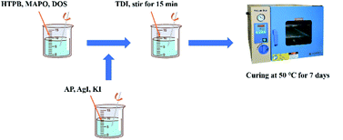
The total mass of raw materials is 50 g. All solid components needed to be screened and dried while all liquid components were dried in a vacuum. To fabricate aerosols, first, the liquid components (HTPB, DOS and MAPO) were mixed and stirred for 5 minutes. Then, the solid components (AP, AgI and KI) were mixed and stirred for 10 minutes. After that, the solid component mixture was added into the liquid mixture, followed by stirring for 15 minutes to achieve a homogeneous phase. Next, the curing agent (TDI) was added and stirred for 15 minutes. Finally, the drug was vacuumed and solidified in an oven at 50 °C for 7 days. The as-fabricated aerosols were sealed and preserved.2.3 Characterization
The ice formation properties of the aerosols were measured via a 0.5 m3 low temperature chamber. The chamber is composed of a temperature and humidity control system, trays, ignition device and sensor system. The nucleation rate of the aerosol was measured via a 1 m3 CAMS (Chinese Academy of Meteorological Sciences) isothermal cloud chamber. The deicing performance of the aerosol catalysts in practical applications was evaluated using an environment climate chamber from China Electric Power Research Institute which was adopted to simulate freezing rain conditions. The chamber has a volume of 60 m3, with cooling power of 5 kW. A cycle refrigeration system was employed to maintain the temperature inside the chamber. In addition, several sets of sensors were equipped to measure both temperature and humidity at various positions inside the chamber. The supercooled water is composed of 100% ultrapure water, with temperature varying from −5 to −2 °C. The height of the nozzle is 5 m, and water was sprayed horizontally from the nozzle.The FTIR spectra were measured using a Nicolet iS50 FT-IR spectrometer in the wavenumber range of 500–4000 cm−1. The scanning electron microscopy (SEM) measurements were carried out on a Regulus 8230 instrument. X-ray diffraction (XRD) patterns were obtained using a Rigaku Smartlab diffractometer with Cu Kα as the X-ray source.
3 Results and discussion
3.1 Fabrication of aerosol catalysts
The aerosols with and without the AgI–KI catalyst were fabricated via a simple pouring method (details provided in the Experimental section and Fig. 1). In this work, the commonly employed AP/HTPB solid composite propellants were adopted,34–36 where AP acts as the oxidizer to produce high energy when being ignited, HTPB serves as the binder to form a polymer matrix, and TDI serves as the curing agent to solidify the matrix. To make comparison, aerosols with and without AgI–KI catalyst were both fabricated. The formulae of the aerosol are summarized in Table 1. Note that the sum of weight percent from HTPB to MAPO is one hundred, with additional components such as AgI and KI contributing extra weight percent. Due to the relatively high price of AgI, it would be impractical to conduct a comprehensive evaluation of every formula. Thus, only two of the best formulae (2# and 3#) were selected to perform deicing measurements.| Formula no. | HTPB | DOS | AP | TDI | MAPO | AgI | KI |
|---|---|---|---|---|---|---|---|
| 1# | 17.1 | 3.2 | 78.5 | 1.0 | 0.2 | 0.0 | 0.0 |
| 2# | 17.1 | 3.2 | 78.5 | 1.0 | 0.2 | 5.0 | 5.0 |
| 3# | 17.1 | 3.2 | 78.5 | 1.0 | 0.2 | 6.0 | 30.0 |
| 4# | 17.1 | 3.2 | 78.5 | 1.0 | 0.2 | 5.0 | 0.0 |
3.2 Ice/snow formation measurements (0.5 m3)
To investigate the deicing performance of the AgI–KI aerosols, we first employed the 0.5 m3 low temperature cabinet. The picture of the cabinet is shown in Fig. S1.† The essential working principle of the apparatus is to evaluate the ice/snow formation performance by measuring the mass of ice/snow dropped on the tray (Fig. 2a). It should be mentioned here that a higher ice/snow mass here is beneficial for glaze icing elimination,37 as it indicated that more supercooled water was consumed before it came into contact with the tray. The ice formation results are summarized in Fig. 2b and Table S1.† All measurements were conducted for 40 minutes, with a temperature of −10 °C to minimize the measurement error, as suggested by previous literature.38 It should be noted that a low temperature generally enhances the nucleation rate, which is beneficial for future deicing performance. Compared to the unmodified aerosols (1#), the AgI–KI aerosols exhibited an average of 50% enhancement in terms of ice mass, with formula 2# (5% AgI–5% KI) showing the best deicing performance (25.2 g) during the measurement.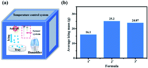 | ||
| Fig. 2 (a) The schematic illustration of 0.5 m3 cabinet employed in this work, and (b) average mass of formed icing of different formulae. | ||
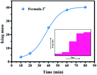
The effects of reaction time on the ice formation properties of formula 2# were also investigated. As shown in Table S2† and Fig. 3, no significant growth of ice mass was observed before reaching 20 minutes. Then, it exhibited a dramatic increase for almost 40 minutes, with the icing mass raised from 6.2 g (20 min, −10 °C) to 25.2 g (40 min, −10 °C), and then to 38.2 g (50 min, −10 °C). After that, the rate of icing formation became smooth. The whole curve was fitted well by a non-linear Boltzmann function, which indicated a different ice formation mechanism from the case where no aerosol was applied. The above results indicated that the aerosol catalyst begins to influence the icing formation after 20 minutes, and the whole process can last up to more than 1 hour. It is worth mentioning here that such a non-linear curve might be related to the diffusion process of aerosol particles after ignition inside the cabinet, as well as the growth process of the formed ice nucleating particles, which all require additional time to complete. We expect further investigation on the kinetics of this process to understand its mechanism.
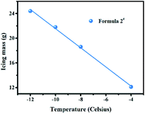
We then conducted the measurements under different temperatures to investigate its impacts on aerosols ice formation performance. Each measurement was conducted for 35 minutes. As can be observed in Fig. 4, as the temperature decreased, the icing mass tended to increase (linear relationship) (e.g., ∼22 g at −10 °C versus ∼24 g at −12 °C), indicating that a lower temperature is beneficial for their deicing performance.
3.3 Nucleation rate measurements (1 m3)
To further investigate the ice formation performance of the aerosol catalysts in a larger volume, a 1 m3 CAMS isothermal cloud chamber (Fig. S2†) was employed to measure their ice nucleation rates. The nucleation rate is defined as the total number of ice nucleating particles generated per unit mass of AgI, which is time-irrelevant. The nucleation rates were measured following methods in the ESI.†39 Fig. S3† shows the picture of ice crystals during the measurement. It is worth mentioning here that in weather modification, one of the most important parameters is the ice nucleation rate, as it would determine the amount of glaze icing formed on the transmission line.All measurements were conducted at a temperature of −10 °C, and the nucleation rate results are summarized in Table 2. It can be observed that all modified aerosols (2# and 3#) exhibited much higher nucleation rates than the unmodified 1# sample, which indicates the excellent catalysis effects of AgI–KI additives. Formula 2# (5% AgI + 5% KI) exhibited the highest nucleation rate of 1.8 × 10¹⁵, in sharp contrast to formula 1# (<107). Moreover, nucleation rates of both formulae 2# and 3# were higher than that of the AgI-only formula (4#, ∼1.4 × 10¹³), indicating an improved nucleation effect of AgI–KI. The aerosols developed in this work also show much better nucleation rates compared to other previous reports, such as AgI–NH4I27 (∼1013, −10 °C), AgI–NaI27 (∼1012, −10 °C), loess24 (∼106, −15 °C), etc. Moreover, in a previous report27 the nucleation rate of a AgI–KI solution (<1013, −10 °C) is much lower than that of the AgI–KI aerosol catalyst developed in this study (∼1015, −10 °C). The higher nucleation rate indicates a faster consumption of freezing rain, which is in principle beneficial for deicing performance, consistent with our previous 0.5 m3 ice formation results.
| Formula | Nucleation rate |
|---|---|
| 1# | Less than 107 |
| 2# | 1.8 × 10¹⁵ |
| 3# | 3.5 × 10¹⁴ |
| 4# | 1.4 × 10¹³ |
3.4 Deicing measurements (60 m3)
To better understand the deicing performance of aerosol samples under practical conditions, a 60 m3 environment climate chamber was employed to simulate freezing rain. During the measurements, two types of nozzle, small sized and extra-fine sized, were both prepared to produce freezing rain with different sizes and falling speeds. The picture showing the inside of the chamber is shown in Fig. S4.† Fig. S5† illustrates the spatial arrangement inside the chamber regarding the distribution of nozzle, transmission lines and rotating rod. The diameters of the rain produced from small sized and extra-fine sized nozzles were estimated to be around 2 mm and less than 0.5 mm, respectively. In addition, the falling speed of rain may be evaluated according to the near free-fall equation, which is similar to the falling process of raindrops in the atmosphere.To conduct the measurements, the temperature inside the tank was maintained below −10 °C via a cycle refrigeration system. The water was sprayed at the 45° direction to form freezing rain. After 5 minutes, the aerosol samples were ignited. Then, intermittent spraying was conducted at 30 s/30 s and the temperature of the nozzle was maintained at around ±3 °C to prevent the nozzle from freezing. After 30 minutes, water spraying was stopped, and the tank was kept closed for 10 minutes. Lastly, the mass of glaze icing formed on transmission lines was measured to determine the deicing performance of aerosols. We evaluated the deicing potential of formula 2#, as it exhibited the best performance during 0.5 m3 and 1 m3 measurements.
| Formula | Glaze icing mass (g) | ||
|---|---|---|---|
| Transmission lines | Rotating rods | Total mass | |
| Blank | 222.7 | 64.3 | 287.0 |
| 2# | 117.2 | 26.4 | 143.6 |
| Reduction (%) | 47.1% | 59.2% | 50.0% |
| Formula | Glaze icing mass (g) | ||
|---|---|---|---|
| Transmission lines | Rotating rods | Total mass | |
| Blank | 417.6 | 105.0 | 522.6 |
| 2# | 344.0 | 62.8 | 406.8 |
| Reduction (%) | 17.6% | 39.0% | 22.2% |
3.5 Characterization of aerosol samples
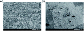
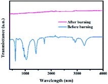
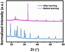
To reveal the change of the aerosol catalyst with formula 2#, its morphologies and chemical properties before and after burning were measured via SEM and FTIR techniques, respectively. The planar SEM images are shown in Fig. 5. As can be observed, the initial aerosol sample consists of many tens of micro-powders. After ignition, numerous tiny nanometer-sized particles were generated, and each may act as a nucleation site to facilitate the ice nucleation process.40 In practical applications, the freezing rain will first come into contact with these aerosol particles before reaching transmission lines, leading to reduced amounts of glaze icing. The FTIR results are presented in Fig. 6. The peaks41,42 could be attributed to AP, HTPB, TDI, etc. However, these peaks no longer existed after burning, which indicated that the components of the products were different from their initial forms. In addition, XRD measurements were conducted to obtain structural information on the sample. As shown in Fig. 7, several new diffraction peaks were detected after burning, which indicates the change of the sample structure.4 Conclusions
In summary, AgI–KI modified aerosols with good combustion performance were fabricated via a vacuum pouring method. By employing a 0.5 m3 low temperature cabinet and 1 m3 CAMS isothermal cloud chamber, the ice formation/nucleation properties of the aerosols were evaluated. We revealed that the aerosols may begin to affect the nucleation process after 20 min, and low temperature is beneficial for ice formation. Future study on the non-linear behavior of the time–icing mass curve is expected to better reveal their reaction mechanism. In addition, after adding AgI–KI catalysts, the nucleation rate increased dramatically from the initial ∼107 to ∼1015. To investigate its deicing performance in a practical environment, a 60 m3 environment climate chamber was adopted. The results indicated that AgI–KI aerosols exhibited excellent deicing performances, consistent with previous nucleation results. Lastly, the morphologies, and chemical and structural properties of the aerosol catalysts before and after experiments were also investigated via SEM, FTIR and XRD techniques. The results suggested that their compositions changed after burning. We expect that there will be more related work on mechanism investigation and practical deicing measurements such as field experiments in the near future.Author contributions
All the deicing experiments were carried out by TS, with assistance from XL, XG, MZ and RY. The characterization of aerosols before and after burning was carried out by TS and FX. The analysis of the data was carried out by TS and FX, with the help of MZ and RY. FX wrote the manuscript with contributions of all the co-authors.Conflicts of interest
There are no conflicts to declare.Acknowledgements
We acknowledge the funding support from the scientific projects of the State Grid Corporation of China (Funding No. 20090941082). We would like to thank China Electric Power Research Institute for providing the 60 m3 environmental climate chamber. We appreciate Gangcheng Yang and Haoming Zhang for their help and support with the self-developed test device and deicing measurements. We thank Zhengjun Su and Liyou Guan from the China Meteorological Administration for their kind support with the nucleation rate measurements. We thank Hanyuan Chen and Benpeng Wang from Beijing Institute of Technology for their support with SEM and XRD characterizations.Notes and references
- D. Y. Leung and Y. Yang, Renewable Sustainable Energy Rev., 2012, 16, 1031–1039 CrossRef.
- A. F. Xu, N. Liu, F. Xie, T. Song, Y. Ma, P. Zhang, Y. Bai, Y. Li, Q. Chen and G. Xu, Nano Lett., 2020, 20, 3864–3871 CrossRef CAS PubMed.
- H. S. Laine, J. Salpakari, E. E. Looney, H. Savin, I. Peters and T. Buonassisi, Energy Environ. Sci., 2019, 2706–2716 RSC.
- A. F. Xu, R. T. Wang, L. W. Yang, N. Liu, Q. Chen, R. LaPierre, N. I. Goktas and G. Xu, J. Mater. Chem. C, 2019, 7, 11104–11108 RSC.
- Y. Veremiichuk, A. Zamulko, S. Zaichenko, A. Mahnitko, K. Berzina and I. Zicmane, 2018.
- P. T. Scott, Altered and Enhanced Iodargyrite with Bismuth Thiiodide for Use in Precipitation Enhancement Operations, Colorado State Univ Fort Collins, 1987 Search PubMed.
- G. Peters, A. M. DiGioia Jr, C. Hendrickson and J. Apt, in Electrical Transmission Line and Substation Structures: Structural Reliability in a Changing World, 2007, pp. 12–26 Search PubMed.
- J. Wei, H. Gao, R. Huang, Z. SU and H. Shaan, Power Syst. Technol., 2012, 36, 276–282 Search PubMed.
- C. Liu and J. Liu, Gaodianya Jishu/High Volt. Eng., 2011, 37, 241–248 Search PubMed.
- L. Makkonen, Philos. Trans. A: Math. Phys. Eng. Sci., 2000, 358, 2913–2939 CrossRef.
- J. Lu, M. Zeng, X. Zeng, Z. Fang and J. Yuan, IEEE Trans. Ind. Appl., 2014, 51, 1997–2002 Search PubMed.
- X.-b. Huang, J.-b. Liu, W. Cai and X.-j. Wang, Power Syst. Technol., 2008, 4, 005 Search PubMed.
- J.-z. Lu, H.-x. Zhang, J.-w. Peng, Z. Fang, B. Li and Z.-l. Jiang, High. Volt. Eng., 2009, 35, 3111–3116 Search PubMed.
- T. Song, F. Xu, R. Yang, X. Guo, M. Zou, Y. Liu and X. Li, AIP Adv., 2021, 11, 025045 CrossRef CAS.
- Q.-f. Li, Z. Fan, Q. Wu, J. Gao, Z.-y. Su and W.-j. Zhou, Power Syst. Technol., 2008, 32, 33–36 Search PubMed.
- H.-S. Oh, C.-B. Park, S.-H. Lee, J.-B. Lee, T.-H. Kim and H.-W. Lee, AIP Adv., 2019, 9, 125229 CrossRef.
- X. Lv and Q. He, Procedia Eng., 2011, 15, 1135–1139 CrossRef.
- J. Laforte, M. Allaire and J. Laflamme, Atmos. Res., 1998, 46, 143–158 CrossRef.
- R. A. McCormick and J. H. Ludwig, Science, 1967, 156, 1358–1359 CrossRef CAS PubMed.
- C. Marcolli, B. Nagare, A. Welti and U. Lohmann, Atmos. Chem. Phys., 2016, 16, 8915–8937 CrossRef CAS.
- L. Xiaofeng, F. Yu and S. Zhengjun, J. Appl. Meteorol. Sci., 2021, 32, 146–159 Search PubMed.
- X. Guo, D. Fu, X. Li, Z. Hu, H. Lei, H. Xiao and Y. Hong, Adv. Atmos. Sci., 2015, 32, 230–249 CrossRef.
- A. G. Detwiler and B. Vonnegut, J. Appl. Meteorol. Climatol., 1981, 20, 1006–1012 CrossRef CAS.
- F. Daxiong, C. Ruzhen and J. Gengwang, J. Appl. Meteorol., 1994, 2, 129–134 Search PubMed.
- A. Hudait and V. Molinero, J. Am. Chem. Soc., 2016, 138, 8958–8967 CrossRef CAS PubMed.
- T. Song, R. Yang, X. Xing, X. Guo, H. Zhang and X. Li, Mater. Res. Innovations, 2015, 19, S8-42–S48-45 CrossRef.
- D. Blair, B. Davis and A. Dennis, J. Appl. Meteorol. Climatol., 1973, 12, 1012–1017 CrossRef CAS.
- B. Davis, L. Johnson and F. J. Moeng, J. Appl. Meteorol. Climatol., 1975, 14, 891–896 CrossRef CAS.
- R. E. Passarelli Jr, H. Chessin and B. Vonnegut, J. Appl. Meteorol., 1974, 13, 946–948 CrossRef.
- J. Zhang, D. Jin, L. Zhao, X. Liu, J. Lian, G. Li and Z. Jiang, Adv. Powder Technol., 2011, 22, 613–616 CrossRef CAS.
- T. Scott Paul, G. Finnegan William and C. Sinclair Peter, J. Appl. Meteorol., 1989, 722–726 CrossRef.
- S. Jing, S. Yueqin, C. Miao, Z. Liuquan and T. Lin, Meteorological, 2015, 41, 1356–1366 Search PubMed.
- Z. Zhongbo, X. Dongying and W. Ling, Meteorol. Environ. Res., 2015, 6, 9–15 Search PubMed.
- S. Chaturvedi and P. N. Dave, Arabian J. Chem., 2019, 12, 2061–2068 CrossRef CAS.
- P. Tu, M. Zou, R. Yang and X. Guo, Thermochim. Acta, 2016, 646, 32–38 CrossRef CAS.
- X. Zhou, M. Zou, F. Huang, R. Yang and X. Guo, Propellants, Explos., Pyrotech., 2017, 42, 417–422 CrossRef CAS.
- F. Xu, Y. Li, N. Liu, Y. Han, M. Zou and T. Song, Crystals, 2021, 11, 241 CrossRef CAS.
- L. Shijun, H. Zhijin and Y. Laiguang, Acta Meteorol. Sin., 2005, 63, 30–40 Search PubMed.
- Z. Su and W. Fang, J. Appl. Meteor. Sci., 2016, 27, 140–147 Search PubMed.
- W. D. Callister and D. G. Rethwisch, Materials Science and Engineering, John Wiley & SonsNY, 2011 Search PubMed.
- L. Mallick, S. Kumar and A. Chowdhury, Thermochim. Acta, 2015, 610, 57–68 CrossRef CAS.
- R. Fitzgerald and M. Brewster, Combust. Flame, 2008, 154, 660–670 CrossRef CAS.
Footnotes |
| † Electronic supplementary information (ESI) available: Method to calculate the nucleation rate and pictures of 0.5 m3, 1 m3 and 60 m3 chambers. See DOI: 10.1039/d1ea00027f |
| ‡ These authors contributed equally to this work. |
| This journal is © The Royal Society of Chemistry 2021 |

