 Open Access Article
Efficient electrochemical water splitting using copper molybdenum sulfide anchored Ni foam as a high-performance bifunctional catalyst†
Aparna
Sajeev
 a,
Vimal Kumar
Mariappan
 a,
Dhanasekar
Kesavan
a,
Karthikeyan
Krishnamoorthy
a,
Dhanasekar
Kesavan
a,
Karthikeyan
Krishnamoorthy
 a and
Sang-Jae
Kim
 *ab
*ab
aNanomaterials & System Laboratory, Major of Mechatronics Engineering, Faculty of Applied Energy System, Jeju National University, Jeju 63243, Republic of Korea. E-mail: kimsangj@jejunu.ac.kr
bDepartment of Advanced Convergence Science & Technology, Jeju National University, Jeju-63243, South Korea
First published on 9th December 2020
Abstract
The necessity of developing a bifunctional catalyst for the hydrogen evolution reaction (HER) and oxygen evolution reaction (OER) has increased due to the urge to meet the future renewable energy requirements. This work demonstrated the use of copper molybdenum sulfide nanostructures on Ni foam (CMS/Ni) as a bifunctional catalyst for the HER and OER. Physicochemical characterizations such as X-ray diffraction, X-ray photoelectron spectroscopy, and field-emission scanning electron microscopic analyses confirmed the formation of hierarchical CMS nanostructures on Ni foam using a hydrothermal method. The CMS/Ni electrocatalyst exhibits excellent electrocatalytic properties in an alkaline electrolyte (1 M KOH) with a low overpotential of about 213 and 350 mV for the HER and OER (to drive a current density of 50 mA cm−2) and Tafel slope values of 80 and 124 mV dec−1, respectively. A lab-scale water electrolyzer is constructed using the CMS/Ni electrocatalyst (as anode and cathode), which requires a low voltage of 1.62 V (at a current density of 50 mA cm−2) for electrochemical water splitting reaction. The multi-current and long-term stability analysis suggested better electrocatalytic properties of the CMS/Ni electrode. Finally, a self-powered water electrolyzer system was constructed via integration of a solar cell with the fabricated CMS/Ni electrolyzer, which demonstrated potential application towards next-generation energy conversion and management systems.
1. Introduction
The development of sustainable green energy technologies is expected to replace the endangered traditional energy resources that cause major global pollution issues in the world.1,2 Therefore, the development of sustainable energy devices such as fuel cells, metal–air batteries, electrocatalytic and photocatalytic conversion techniques is focused on solving the overall energy crisis.3–8 Electrochemical water splitting is a promising energy process that can produce zero-carbon emission hydrogen gas via electrocatalytic energy conversion. Furthermore, it has more benefits than using the power from wind and solar energy for cost-effective production.2,9–11 The principle of electrochemical water splitting occurs via the hydrogen evolution reaction (HER) at the cathode and oxygen evolution reaction (OER) at the anode.5 The choice of electrocatalytic materials significantly impacts the device performance (low overpotentials) to reach the level of widely used HER (platinum-based) and OER catalysts (iridium/ruthenium-based).12,13 The high cost of these noble metals limits their wide practical applications, especially in the development of large-scale manufacturing.14 This results in huge demand to develop low-cost, noble metal-free catalysts with high electrocatalytic properties.In this context, developing a bifunctional catalyst capable of driving both HER and OER reactions is of great interest in reducing the overall manufacturing cost and preventing cross-contamination during a long cycle.15 Currently, transition metal-based chalcogenides, phosphides, oxides, and their derivatives are being examined as bifunctional catalysts in an alkaline medium.2,16–21 However, these materials still need to be further engineered to reduce the overpotentials in both the anode and cathode during the electrochemical water splitting reactions.22 It is expected that multicomponent transition metal-based catalysts can be an ideal candidate for electrocatalytic reactions due to their high redox states and improved conductivity over their single component ones.23,24 For instance, 2D MoS2 nanosheets are examined as promising HER catalysts in the water-splitting reactions due to their ability to chemisorb hydrogen (in both acidic and alkaline environment) via the S-edge sites in the 2D lattice.10 However, these materials are proven to be a poor OER catalyst, which was tailored via incorporation of a transition metal or nanohybrids decoration to enhance the OER. Recently, Zhu et al. demonstrated this synergistic effect approach through preparing a Co9S8/MoS2 composite, which established a higher catalytic activity than their individual performances because of the increased charge transfer between the Mo and Co atoms through S-linkage.25 Wang et al. reported a CoNi2S4 electrocatalyst synthesized through a one pot hydrothermal method that shows an electrochemical activity of HER with a Tafel slope value of 85 mV dec−1 with an overpotential of 255 mV at 10 mA cm−2.26 Shichun et al. reported that a Mo–N/C@MoS2 electrocatalyst showed an electrochemical OER activity which required an overpotential of 390 mV to attain a current density of 10 mA cm−2.27 In the view of lowering the overpotential values of the HER/OER and reducing the required voltage for water splitting reactions in full devices, it is strongly required to develop novel bifunctional catalysts.
In these regards, copper molybdenum sulfide (Cu2MoS4, CMS) from the family of Cu2MX4 is more attractive due to its intrinsic physical and chemical properties with rich electrochemistry.7,28 CMS nanostructures prepared via different chemical methods have been explored as an excellent photocatalytic (due to wide bandgap),29 HER,30 and pseudocapacitive material.31 Our recent studies have demonstrated the exceptional capacitive nature of the CMS nanostructures in 1 M Na2SO4 electrolyte with a specific capacitance of 265.62 F g−1.32 Even though CMS powders were experimentally demonstrated as a HER catalyst, their performance as a catalyst for the OER and effectiveness in overall electrochemical water splitting is not yet studied. In this work, we have demonstrated the use of hierarchical CMS nanostructures grown on Ni foam as a novel bifunctional catalyst for water splitting applications. Furthermore, we also presented a self-powered system via integration of a solar power station to drive the CMS water electrolyzer as a proof of concept.
2. Experimental section
2.1 Materials
Copper(II) sulfate pentahydrate (CuSO4·5H2O), sodium molybdate (Na2MoO4), thioacetamide (CH3CSNH2), sodium sulfate (Na2SO4), copper(II) oxide (CuO), and ethylene glycol (C2H6O2) were procured from Daejung Chemicals Ltd, South Korea. The nickel (Ni) foam (thickness 1.7 mm) was purchased from Heze Jiao tong Xinda Import and Export Co., Ltd. Prior to the hydrothermal process, Ni foam was pre-cleaned with diluted HCl followed by acetone, and deionized (DI) water via a sonication process to remove the presence of dust and native surface oxide layer.332.2 Growth of copper molybdenum sulfide nanostructures on Ni foam
A hydrothermal method was used to grow the copper molybdenum sulfide (CMS) nanostructures on the porous Ni foam using the same procedure reported in our previous work.32 Briefly, Na2MoO4 and CH3CSNH2 in the weight ratio of 1![[thin space (1/6-em)]](https://www.rsc.org/images/entities/char_2009.gif) :
:![[thin space (1/6-em)]](https://www.rsc.org/images/entities/char_2009.gif) 2 were dissolved in 60 mL of ethylene glycol under an ultrasonication process for 1 h. This process led to the formation of a light-yellowish, green-colored solution ensuring the complete dissolution of Na2MoO4 and CH3CSNH2 in C2H6O2. Subsequently, 40 mg of CuO was added slowly to the above solution and ultrasonicated until the color of the solution turned dark brown. The prepared precursor solution was later transferred to a Teflon lined stainless steel autoclave (100 mL) in which the precleaned Ni-foam was immersed. The hydrothermal reaction was carried out by placing the autoclave in a hot air oven for 15 h at 150 °C and then naturally allowed to cool down to room temperature. Hereafter, the settled black colored CMS powders on the bottom of the vessel and CMS/Ni foam substrate were carefully washed using water and ethanol to remove the impurities. Finally, the CMS powders and CMS/Ni foam samples were dried in an oven at 60 °C for 12 h.
2 were dissolved in 60 mL of ethylene glycol under an ultrasonication process for 1 h. This process led to the formation of a light-yellowish, green-colored solution ensuring the complete dissolution of Na2MoO4 and CH3CSNH2 in C2H6O2. Subsequently, 40 mg of CuO was added slowly to the above solution and ultrasonicated until the color of the solution turned dark brown. The prepared precursor solution was later transferred to a Teflon lined stainless steel autoclave (100 mL) in which the precleaned Ni-foam was immersed. The hydrothermal reaction was carried out by placing the autoclave in a hot air oven for 15 h at 150 °C and then naturally allowed to cool down to room temperature. Hereafter, the settled black colored CMS powders on the bottom of the vessel and CMS/Ni foam substrate were carefully washed using water and ethanol to remove the impurities. Finally, the CMS powders and CMS/Ni foam samples were dried in an oven at 60 °C for 12 h.
2.3 Instrumentation
The phase and crystallinity of the CMS/Ni electrode were determined using an X-ray diffractometer system (Empyrean) with Cu-Kα radiation (λ = 1.5418 Å). The analysis of the elements chemical state in the CMS/Ni foam was done using an X-ray photoelectron spectrometer (ESCA-2000, VG Microtech Ltd). The surface morphology and elemental mapping analysis were scrutinized with field-emission scanning electron microscopy (TESCAN, MIRA3) under various magnifications using an energy dispersive X-ray (EDS) spectroscope and a transmission emission scanning electron microscope (HR-TEM, JEOL JEM 2011, JEOL Ltd).2.4 Electrochemical measurements
All of the electrochemical measurements were carried on Autolab PGSTAT302N electrochemical workstation. The individual electrode properties of the CMS/Ni electrode for the HER and OER were accessed using a three-electrode configuration test by employing the working electrode (CMS/Ni), reference electrode (Ag/AgCl), and counter electrode (platinum sheet) respectively. The electrochemical measurements such as linear sweep voltammetry (LSV) were performed using 1 M KOH aqueous electrolyte at a scan rate of 10 mV s−1. The potential values provided in the LSV polarization curves were iR-corrected unless specifically indicated, and the potential values were reported with respect to RHE (converted from the Ag/AgCl scale using a calibration). The electrochemical active surface area of the CMS/Ni electrocatalyst was determined using the ratio of double-layer capacitance (Cdl) to that of the specific capacitance as reported in the literature.34–36 The double-layer capacitance (Cdl) was estimated from the non-faradaic region through CVs recorded at different scan rates. The overall water splitting experiments were performed using a two-electrode configuration system, using two symmetric CMS/Ni foam as the cathode and anode, respectively. Furthermore, the practical applicability of the CMS/Ni water electrolyzer was demonstrated by utilizing three solar panels (connected in parallel) as a sustainable power source to drive the water electrolyzer for hydrogen production.3. Results and discussion
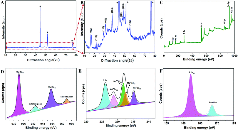
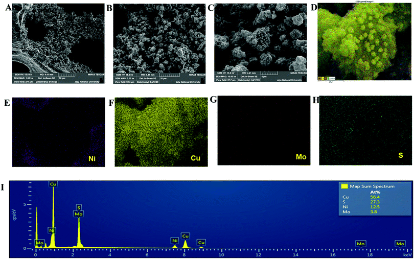
The copper molybdenum sulfide nanostructures were grown on the surface of Ni foam via a one-step hydrothermal route as reported in our earlier work,32 and the product is denoted as the CMS/Ni electrode. The X-ray diffraction (XRD) pattern of the CMS/Ni electrode shows that the diffraction peaks correspond to the bare Ni foam (Fig. 1(A)), and tetragonal Cu2MoS4 (Fig. 1(B)). There are no peaks relayed to any other form of single component sulfides detected in the XRD pattern, which suggested the formation of CMS/Ni foam. Fig. 1(C) exhibits the XPS survey spectrum of the CMS/Ni foam, indicating the presence of elements such as Mo 3d, Cu 2p, S 2p, and Ni 2p, with C 1s and O 1s. The core-level spectrum of the Cu 2p states (Fig. 1(D)) exhibited the existence of the two prominent peaks at 953.15 eV (Cu 2p1/2) and 933.10 eV (Cu 2p3/2) with a peak separation of 20.05 eV suggesting that the oxidation state of Cu in CMS/Ni is about +1. The deconvoluted spectrum of the Mo 3d states (Fig. 1(E)) shows the presence of peaks due to Mo4+ 3d5/2 (228.75 eV), Mo4+ 3d3/2 (232.63 eV), Mo6+ 3d5/2 (231.89 eV), and Mo6+ 3d3/2 (235.16 eV) and with an additional peak at 226.16 eV (S 2s), respectively.37Fig. 1(F) shows the core-level spectrum of the S 2p state, presenting two peaks at 162.2 and 168.58 eV that correspond to S 2p3/2 and their satellites, suggesting that the oxidation state of S 2p in the CMS/Ni is found to be −2. Fig. S1, ESI† describes the core level spectrum of the Ni 2p states present in the CMS/Ni. Fig. 2 summarizes the morphological and elemental analysis of the CMS/Ni foam. The field emission scanning electron microscopic (FE-SEM) image given in Fig. 2(A–C) with different levels of magnification suggested the uniform growth of CMS nanostructures (with size in the range from 100 to 200 nm) on the surface of the Ni foam. Fig. 2(D) shows the micrograph used for elemental analysis to identify the elements (Ni, Cu, Mo and S) present in CMS/Ni foam as given in Fig. 2(E–H). The EDS spectrum given in Fig. 2(I) further confirms the presence of Cu, Mo and S elements in the prepared CMS/Ni foam. The high-resolution transmission electron micrographs (HR-TEM) of the CMS nanostructures (peeled off from the CMS/Ni) recorded under various magnifications are provided in Fig. 3(A–C). This showed that the size of the CMS nanostructures lies in the range of 50 to 100 nm, respectively. The corresponding elemental maps of CMS nanostructures given in Fig. 3(D–F) highlight the homogeneous distribution of Cu, Mo, and S elements present in the prepared CMS.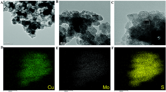 | ||
| Fig. 3 (A–C) High-resolution transmission electron micrographs of CMS nanostructures and (D–F) elemental maps of Cu, Mo, and S present in the CMS. | ||
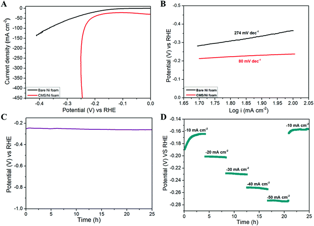
Fig. 4 shows the HER properties of the CMS/Ni foam compared with bare Ni foam using an aqueous electrolyte of 1 M KOH at room temperature. Fig. 4(A) depicts the LSV polarization curve of bare Ni and CMS/Ni foam for the HER, which shows the low onset potential (−0.18 V vs. RHE) of the CMS/Ni electrocatalyst compared to that of the bare Ni electrode. The porous CMS/Ni electrocatalyst attains a HER current density of 50 mA cm−2 at an overpotential (η50) of 213 mV, which is lower compared to the bare Ni foam electrodes with an overpotential of 283 mV. The HER performance of the CMS/Ni foam electrocatalyst is better compared to the recently reported electrocatalysts such as NiCo2S4 NW/NF (η10 = 210 mV), CoSx/Ni3S2@NF NF (η10 = 240 mV), Ni–Co–S (η10 = 280 mV), and others given in Table S1, ESI.†![[thin space (1/6-em)]](https://www.rsc.org/images/entities/char_2009.gif) 38–40Fig. 4(B) shows the Tafel plots obtained over the region from 50 to 100 mA cm−2, which showed Tafel slope values of 80 mV dec−1 smaller than CoSx/Ni3S2@NF (133.32 mV dec−1), Co9S8 HNSs (111 mV dec−1), and so on.39,41 The Tafel slope value is calculated to analyze the possible HER kinetics of the CMS/Ni electrocatalyst, as shown in Fig. 4(B). The Tafel slope of 80 mV dec−1 was found for the CMS/Ni electrocatalyst, whereas it is about 274 mV dec−1 for the bare Ni electrode. The CMS/Ni electrocatalyst shows a very low Tafel slope value compared with Ni foam, which indicated that the former possesses a hassle-free HER kinetics. Fig. 4(C) shows the long-term stability of the CMS/Ni electrocatalyst analyzed using chronopotentiometry (at 50 mA cm−2) for 25 h. It showed a potential of −0.250 V initially, which increased up to −0.260 V after continuous reaction and is stable until 25 h, which suggested the electrochemical stability of the CMS/Ni electrocatalyst. The observed small increase in the potential values during the initial cycles might be due to the electro-activation effect as a cause of the wettability of the CMS/Ni electrocatalyst. Fig. S2, ESI† shows the HER polarization curves of the CMS/Ni electrocatalyst before and after stability tests, which shows an increase in overpotential value from 213 to 229 mV. This small shift in overpotential value is a reasonable one which also affirms their better electrochemical stability. Fig. 4(D) shows the HER multi-current analysis of the CMS/Ni electrocatalyst over 25 h analyzed using the chronopotentiometry method (using different applied current densities ranging from −10 to −50 mA cm−2). It showed that the measured potential values were recovered after ramping with different levels of applied current ranges after 25 h. These measurements indicated the use of the CMS/Ni electrocatalyst as a promising candidate for HER applications.
38–40Fig. 4(B) shows the Tafel plots obtained over the region from 50 to 100 mA cm−2, which showed Tafel slope values of 80 mV dec−1 smaller than CoSx/Ni3S2@NF (133.32 mV dec−1), Co9S8 HNSs (111 mV dec−1), and so on.39,41 The Tafel slope value is calculated to analyze the possible HER kinetics of the CMS/Ni electrocatalyst, as shown in Fig. 4(B). The Tafel slope of 80 mV dec−1 was found for the CMS/Ni electrocatalyst, whereas it is about 274 mV dec−1 for the bare Ni electrode. The CMS/Ni electrocatalyst shows a very low Tafel slope value compared with Ni foam, which indicated that the former possesses a hassle-free HER kinetics. Fig. 4(C) shows the long-term stability of the CMS/Ni electrocatalyst analyzed using chronopotentiometry (at 50 mA cm−2) for 25 h. It showed a potential of −0.250 V initially, which increased up to −0.260 V after continuous reaction and is stable until 25 h, which suggested the electrochemical stability of the CMS/Ni electrocatalyst. The observed small increase in the potential values during the initial cycles might be due to the electro-activation effect as a cause of the wettability of the CMS/Ni electrocatalyst. Fig. S2, ESI† shows the HER polarization curves of the CMS/Ni electrocatalyst before and after stability tests, which shows an increase in overpotential value from 213 to 229 mV. This small shift in overpotential value is a reasonable one which also affirms their better electrochemical stability. Fig. 4(D) shows the HER multi-current analysis of the CMS/Ni electrocatalyst over 25 h analyzed using the chronopotentiometry method (using different applied current densities ranging from −10 to −50 mA cm−2). It showed that the measured potential values were recovered after ramping with different levels of applied current ranges after 25 h. These measurements indicated the use of the CMS/Ni electrocatalyst as a promising candidate for HER applications.
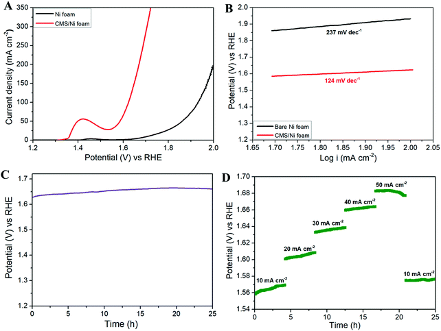
Fig. 5 shows the OER properties of the CMS/Ni foam in comparison with bare Ni foam using an aqueous electrolyte of 1 M KOH at room temperature. Fig. 5(A) depicts the LSV polarization curve of bare Ni and CMS/Ni foam for the OER, which shows the lower onset potential (1.5 V vs. RHE) of the CMS/Ni electrocatalyst than that of the bare Ni electrode. This suggested that the improved OER catalytic properties of the Ni electrode after the growth of CMS nanostructures on their surface. In Fig. 5(A), an intense oxidation peak was identified at ∼1.43 V vs. RHE as a result of Ni(II)–Ni(III) conversion within the electrochemical process.42 Due to this reaction, the oxygen evolution overpotential (η) measurement at 10 mA cm−2 cannot be calculated accurately. Therefore, we have reported the overpotential at a higher current density (50 mA cm−2) widely practiced for binder-free electrodes. The porous CMS/Ni electrocatalyst attains OER current density of 50 mA cm−2 at an overpotential (η50) of 350 mV, lower than the bare Ni foam electrodes with an overpotential of 570 mV. The obtained overpotential value of the CMS/Ni electrocatalyst (η50 = 350 mV) is better than that of the reported electrocatalysts such as CuS (η10 = 400 mV), Cu2S–Ni3S2/NF (η10 = 329 mV), MoS2@CoO (η10 = 325 mV), respectively.43–45 The Tafel slope value is calculated further to analyze the possible OER kinetics of the CMS/Ni electrocatalyst, as shown in Fig. 5(B). The Tafel slope of 124 mV dec−1 was found for the CMS/Ni electrocatalyst, whereas it is about 237 mV dec−1 for the bare Ni electrode. The CMS/Ni electrocatalyst shows a very low Tafel slope compared with Ni foam and other recently reported TMO and TMCs (as seen in Table S2, ESI†), which indicated that the former possesses a hassle-free OER kinetics. These values suggested that the OER reaction that occurred at the surface of the CMS/Ni electrode was governed by a one-electron transfer process in accordance with the critical assessment of the electrochemical water splitting reaction suggested by S. Kundu et al.46Fig. 5(C) shows the long-term stability of the CMS/Ni electrocatalyst analyzed using chronopotentiometry (at 50 mA cm−2) for 25 h. It showed that a potential of 1.62 V was observed initially, which was increased up to 1.66 V after continuous reaction and is stable until 25 h, which suggested the electrochemical stability of the CMS/Ni electrocatalyst. The observed small increase in the potential values during the initial cycles might be due to the electro-activation effect due to the wettability of the CMS/Ni electrocatalyst. Fig. S3, ESI† shows the OER polarization curves of the CMS/Ni electrocatalyst before and after stability tests, which shows an increase in the overpotential values from 350 to 380 mV. This small shift in overpotential values is a reasonable one, which also affirms their better electrochemical stability. Fig. 5(D) shows the OER multi-current analysis of the CMS/Ni electrocatalyst over 25 h as analyzed using the chronopotentiometry method (using different applied current densities ranging from 10 to 50 mA cm−2). This showed that the measured potential values were recovered after ramping with different levels of applied current range after 25 h. These measurements indicated the use of the CMS/Ni electrocatalyst as a promising candidate for OER applications. Electrochemical impedance spectroscopy is a critical analysis to understand the mechanism of charge and ionic transport in an electrochemical system.47 Fig. S4, ESI† depicts the Nyquist plot of the CMS/Ni electrocatalyst, which revealed the presence of quasi semi-circles at a high frequency (due to charge transfer resistance) followed by a straight line (Warburg impedance) at the low-frequency regime. The solution resistance (Rs) and quasi charge-transfer resistance (Rct) of the CMS/Ni electrode are found to be 0.85 Ω and 1.4 Ω, which confirms the better conductivity of the prepared CMS/Ni electrode. To determine the electrochemically active surface area (ECSA) of the CMS/Ni electrode, the cyclic voltammograms (CV) of the CMS/Ni electrocatalyst were recorded over the potential from 0.575 to 0.875 V (as given in Fig. S5(A), ESI†) which shows a typical capacitive nature. The anodic and cathodic peak current shows a linear increase in the current ranges in accordance with an increase in the scan rate as seen from Fig. S5(B), ESI† from which the double-layer capacitance (Cdl) of the CMS/Ni electrode is determined as 4.45 mF with a corresponding ECSA of 111.25 cm2.
The above studies suggested the HER and OER properties of the prepared CMS/Ni electrodes tested using the half-cell configuration. However, it is also essential to examine the properties of the CMS/Ni electrocatalyst using full-cell configuration to examine their device specific properties for electrochemical water splitting reactions. Therefore, we have fabricated the CMS/Ni electrode-based lab-scale water electrolyzer (beaker type cell) using two identical CMS/Ni electrodes. Fig. 6(A) shows the LSV polarization curve of a non-precious CMS/Ni electrode-based alkaline water electrolyzer. This indicates that the CMS/Ni water electrolyzer requires a minimum voltage of 1.62 V to attain 10 mA cm−2, which is a benchmark current value for practical applications. The obtained voltage values for the CMS/Ni water electrolyzer are comparable to that of the precious electrocatalyst and lower compared to the other recently reported bifunctional electrocatalysts such as CoNi2S4/Ni3S2@NF (1.65 V), Co9S8/Ni3S2 (1.64 V), Co9S8@MoS2 (1.67 V), NiCo2S4 NA/CC (1.68 V) and others listed in Table S3 (ESI†).48–50 The excellent electrochemical performance of the CMS/Ni electrocatalyst for the HER and OER is ascribed to several factors: (i) the presence of hierarchical nanostructures,38 (ii) the elimination of the insulating binder,33 (iii) direct integration of the CMS nanostructures on Ni foam resulting in efficient electron transfer kinetics,42 and (iv) the improved electrical conductivity and electrochemical reactivity of CMS nanostructures.51
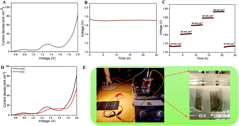
Fig. 6(B) shows the long-term durability test of the fabricated CMS/Ni water electrolyzer, which shows that the voltage value varies from 1.75 to 1.71 V (10 mA cm−2), suggesting their superior stability. The multi-current analysis of the fabricated CMS/Ni water electrolyzer (shown in Fig. 6(C)) shows that the voltage values are changed with respect to the applied current ranges and recovered back. Fig. 6(D) shows the LSV profiles of the CMS/Ni water electrolyzer, which shows only a small noticeable change in the overpotential values even after 50 h of continuous operation. To analyze the structural stability of the CMS/Ni electrode, we have performed their XRD and FE-SEM analysis after a long-term stability test. Fig. S6(A) (ESI†) shows the XRD pattern of the CMS/Ni electrode before and after electrochemical stability (after 25 h). It showed significant differences as follows: The characteristic diffraction peak of the CMS nanostructure at 16.1° (corresponding to the (002) plane of CMS) becomes broadened as a result of long-term ion intercalation into the layered sites of the CMS nanostructures. Fig. S6(B–D), ESI† confirms that there is no significant change in the morphology of the CMS/Ni electrode after electrochemical stability tests and it also highlights the good adherence of the CMS on the Ni foam. The EDX spectrum shown in Fig. S6(E), ESI† shows the presence of K and O elements due to the use of KOH electrolyte in addition to the C, Mo, S, and Ni elements present in CMS/Ni. Fig. S6(F–L), ESI† confirms the presence of potassium and oxygen from KOH on the surface of the CMS/Ni electrode. The XRD, FE-SEM and elemental mapping indicated that the CMS/Ni foam possesses good structural stability, which is an important parameter for use in a water electrolyzer. Finally, as a proof of concept, we have integrated the solar cells with the fabricated CMS/Ni water electrolyzer for energy efficient production of hydrogen fuel as shown in Fig. 6(E). Here, three solar cells were connected in parallel to drive the CMS/Ni water electrolyzer, which results in the splitting of water into hydrogen and oxygen gas bubbles as evident from the digital photograph given in Fig. 6(E) and Video S1 (ESI†). These studies suggested the use of non-precious CMS/Ni electrocatalysts for effective water splitting using solar energy, which is one of the cost-effective methods for the large-scale production of hydrogen in real life.
4. Conclusion
In conclusion, a cost-effective CMS/Ni foam electrocatalyst was developed and explored as a bifunctional electrocatalyst for electrochemical water splitting. The binder free CMS/Ni electrocatalyst exhibit excellent electrochemical HER and OER with low overpotential values of 213 mV and 350 mV with a low Tafel slope and excellent electrochemical stability. A water electrolyzer fabricated using a CMS/Ni electrocatalyst (as both the anode and cathode) showed that a very low voltage of 1.62 V is required to attain 50 mA cm−2. Here, we have also successfully demonstrated the real time application of electrochemical water splitting driven by solar energy using the fabricated CMS/Ni electrocatalyst. These experimental strategies might give new inspiration for the researchers to focus on ternary transition metal chalcogenides in alkaline medium, which will accelerate the research into the field of clean and cost-effective electrocatalysis.Conflicts of interest
There are no conflicts to declare.Acknowledgements
This work was supported by the Basic Science Research Program through the National Research Foundation of Korea (NRF) grant funded by the Korean government (MSIT) (2018R1A4A1025998, 2019R1A2C3009747, and 2020R1A2C2007366).References
- Z. W. She, J. Kibsgaard, C. F. Dickens, I. Chorkendorff, J. K. Nørskov and T. F. Jaramillo, Science, 2017, 355, 6321, DOI:10.1126/science.eaad4998.
- J. Zhu, L. Hu, P. Zhao, L. Y. S. Lee and K. Y. Wong, Chem. Rev., 2020, 120, 851–918 CrossRef CAS.
- M. R. Palacín, Chem. Soc. Rev., 2009, 38, 2565–2575 RSC.
- J. Suntivich, H. A. Gasteiger, N. Yabuuchi, H. Nakanishi, J. B. Goodenough and Y. Shao-Horn, Nat. Chem., 2011, 3, 546–550 CrossRef CAS.
- N. T. Suen, S. F. Hung, Q. Quan, N. Zhang, Y. J. Xu and H. M. Chen, Chem. Soc. Rev., 2017, 46, 337–365 RSC.
- H. Ahmad, S. K. Kamarudin, L. J. Minggu and M. Kassim, Renewable Sustainable Energy Rev., 2015, 43, 599–610 CrossRef CAS.
- D. C. Nguyen, D. T. Tran, T. L. L. Doan, D. H. Kim, N. H. Kim and J. H. Lee, Adv. Energy Mater., 2020, 10, 1903289 CrossRef CAS.
- B. Y. Guan, S. L. Zhang and X. W. D. Lou, Angew. Chem., Int. Ed., 2018, 57, 6176–6180 CrossRef CAS.
- J. N. Tiwari, N. K. Dang, S. Sultan, P. Thangavel, H. Y. Jeong and K. S. Kim, Nat. Sustainability, 2020, 3, 556–563 CrossRef.
- T. F. Jaramillo, K. P. Jørgensen, J. Bonde, J. H. Nielsen, S. Horch and I. Chorkendorff, Science, 2007, 317, 100–102 CrossRef CAS.
- I. Roger, M. A. Shipman and M. D. Symes, Nat. Rev. Chem., 2017, 1, 0003 CrossRef CAS.
- J. Zheng, W. Sheng, Z. Zhuang, B. Xu and Y. Yan, Sci. Adv., 2016, 2, 1–9 Search PubMed.
- V. Pfeifer, T. E. Jones, J. J. Velasco Vélez, C. Massué, M. T. Greiner, R. Arrigo, D. Teschner, F. Girgsdies, M. Scherzer, J. Allan, M. Hashagen, G. Weinberg, S. Piccinin, M. Hävecker, A. Knop-Gericke and R. Schlögl, Phys. Chem. Chem. Phys., 2016, 18, 2292–2296 RSC.
- Y. Peng, K. Jiang, W. Hill, Z. Lu, H. Yao and H. Wang, ACS Appl. Mater. Interfaces, 2019, 11, 3971–3977 CrossRef CAS.
- S. Siracusano, N. Hodnik, P. Jovanovic, F. Ruiz-Zepeda, M. Šala, V. Baglio and A. S. Aricò, Nano Energy, 2017, 40, 618–632 CrossRef CAS.
- S. Chandrasekaran, L. Yao, L. Deng, C. Bowen, Y. Zhang, S. Chen, Z. Lin, F. Peng and P. Zhang, Chem. Soc. Rev., 2019, 48, 4178–4280 RSC.
- J. Yin, J. Jin, H. Lin, Z. Yin, J. Li, M. Lu, L. Guo, P. Xi, Y. Tang and C. H. Yan, Adv. Sci., 2020, 7, 1903070 CrossRef CAS.
- S. Anantharaj, S. R. Ede, K. Sakthikumar, K. Karthick, S. Mishra and S. Kundu, ACS Catal., 2016, 6, 8069–8097 CrossRef CAS.
- J. Joo, T. Kim, J. Lee, S. Il Choi and K. Lee, Adv. Mater., 2019, 31, 1–23 CrossRef.
- G. Fu and J. M. Lee, J. Mater. Chem. A, 2019, 7, 9386–9405 RSC.
- P. Zhang, X. F. Lu, J. Nai, S. Zang and X. W. (David) Lou, Adv. Sci., 2019, 6, 1900576 CrossRef.
- H. Xu, S. Ci, Y. Ding, G. Wang and Z. Wen, J. Mater. Chem. A, 2019, 7, 8006–8029 RSC.
- W. Liu, J. Bao, M. Guan, Y. Zhao, J. Lian, J. Qiu, L. Xu, Y. Huang, J. Qian and H. Li, Dalton Trans., 2017, 46, 8372–8376 RSC.
- Y. Yan, B. Y. Xia, B. Zhao and X. Wang, J. Mater. Chem. A, 2016, 4, 17587–17603 RSC.
- H. Zhu, J. Zhang, R. Yanzhang, M. Du, Q. Wang, G. Gao, J. Wu, G. Wu, M. Zhang, B. Liu, J. Yao and X. Zhang, Adv. Mater., 2015, 27, 4752–4759 CrossRef CAS.
- D. Wang, X. Zhang, Z. Du, Z. Mo, Y. Wu, Q. Yang, Y. Zhang and Z. Wu, Int. J. Hydrogen Energy, 2017, 42, 3043–3050 CrossRef CAS.
- I. S. Amiinu, Z. Pu, X. Liu, K. A. Owusu, H. G. R. Monestel, F. O. Boakye, H. Zhang and S. Mu, Adv. Funct. Mater., 2017, 27, 1702300 CrossRef.
- W. Chen, H. Chen, H. Zhu, Q. Gao, J. Luo, Y. Wang, S. Zhang, K. Zhang, C. Wang, Y. Xiong, Y. Wu, X. Zheng, W. Chu, L. Song and Z. Wu, Small, 2014, 10, 4637–4644 CrossRef CAS.
- K. Zhang, Y. Lin, C. Wang, B. Yang, S. Chen, S. Yang, W. Xu, H. Chen, W. Gan, Q. Fang, G. Zhang, G. Li and L. Song, J. Phys. Chem. C, 2016, 120, 13120–13125 CrossRef CAS.
- P. D. Tran, M. Nguyen, S. S. Pramana, A. Bhattacharjee, S. Y. Chiam, J. Fize, M. J. Field, V. Artero, L. H. Wong, J. Loo and J. Barber, Energy Environ. Sci., 2012, 5, 8912–8916 RSC.
- D. Y. W. Yu, R. L. Lee, R. Yi, S. Y. Chiam and P. D. Tran, Electrochim. Acta, 2014, 115, 337–343 CrossRef CAS.
- S. Sahoo, K. Krishnamoorthy, P. Pazhamalai and S. J. Kim, Nanoscale, 2018, 10, 13883–13888 RSC.
- V. K. Mariappan, K. Krishnamoorthy, P. Pazhamalai, S. Sahoo, S. S. Nardekar and S.-J. J. Kim, Nano Energy, 2019, 57, 307–316 CrossRef CAS.
- P. Thangavel, M. Ha, S. Kumaraguru, A. Meena, A. N. Singh, A. M. Harzandi and K. S. Kim, Energy Environ. Sci., 2020, 13, 3447–3458 RSC.
- C. C. L. McCrory, S. Jung, I. M. Ferrer, S. M. Chatman, J. C. Peters and T. F. Jaramillo, J. Am. Chem. Soc., 2015, 137, 4347–4357 CrossRef CAS.
- H. Yuan, S. Wang, X. Gu, B. Tang, J. Li and X. Wang, J. Mater. Chem. A, 2019, 7, 19554–19564 RSC.
- J. Zhou, G. Xu, Z. Zhang and H. Wang, New J. Chem., 2019, 43, 9574–9582 RSC.
- A. Sivanantham, P. Ganesan and S. Shanmugam, Adv. Funct. Mater., 2016, 26, 4661–4672 CrossRef CAS.
- S. Shit, S. Chhetri, W. Jang, N. C. Murmu, H. Koo, P. Samanta and T. Kuila, ACS Appl. Mater. Interfaces, 2018, 10, 27712–27722 CrossRef CAS.
- A. Irshad and N. Munichandraiah, ACS Appl. Mater. Interfaces, 2017, 9, 19746–19755 CrossRef CAS.
- X. Ma, W. Zhang, Y. Deng, C. Zhong, W. Hu and X. Han, Nanoscale, 2018, 10, 4816–4824 RSC.
- A. Sivanantham and S. Shanmugam, Appl. Catal., B, 2017, 203, 485–493 CrossRef CAS.
- P. Cheng, C. Yuan, Q. Zhou, X. Hu, J. Li, X. Lin, X. Wang, M. Jin, L. Shui, X. Gao, R. Nötzel, G. Zhou, Z. Zhang and J. Liu, J. Phys. Chem. C, 2019, 123, 5833–5839 CrossRef CAS.
- A. Shankar, R. Elakkiya and G. Maduraiveeran, New J. Chem., 2020, 44, 5071–5078 RSC.
- K. S. Bhat and H. S. Nagaraja, ChemistrySelect, 2020, 5, 2455–2464 CrossRef CAS.
- S. Anantharaj, S. R. Ede, K. Karthick, S. Sam Sankar, K. Sangeetha, P. E. Karthik and S. Kundu, Energy Environ. Sci., 2018, 11, 744–771 RSC.
- K. Krishnamoorthy, P. Pazhamalai, V. K. Mariappan, S. S. Nardekar, S. Sahoo and S.-J. Kim, Nat. Commun., 2020, 11, 2351 CrossRef CAS.
- D. Liu, Q. Lu, Y. Luo, X. Sun and A. M. Asiri, Nanoscale, 2015, 7, 15122–15126 RSC.
- W. Dai, K. Ren, Y. an Zhu, Y. Pan, J. Yu and T. Lu, J. Alloys Compd., 2020, 844, 156252 CrossRef CAS.
- J. Bai, T. Meng, D. Guo, S. Wang, B. Mao and M. Cao, ACS Appl. Mater. Interfaces, 2018, 10, 1678–1689 CrossRef CAS.
- S. Sahoo, K. Krishnamoorthy, P. Pazhamalai, V. K. Mariappan and S. J. Kim, Int. J. Hydrogen Energy, 2018, 43, 12222–12232 CrossRef CAS.
Footnote |
| † Electronic supplementary information (ESI) available. See DOI: 10.1039/d0ma00688b |
| This journal is © The Royal Society of Chemistry 2021 |

