 Open Access Article
Creative Commons Attribution 3.0 Unported Licence
A versatile platform of poly(acrylic acid) cryogel for highly efficient photothermal water evaporation†
Jia-Yun
Wang
a,
Xiao-Xiao
Guo
a,
Jun
Chen
a,
Shi-Chang
Hou
a,
Hui-Juan
Li
a,
Abdul
Haleem
a,
Sheng-Qi
Chen
 b and
Wei-Dong
He
 *a
*a
aCAS Key Laboratory of Soft Matter Chemistry, Department of Polymer Science and Engineering, University of Science and Technology of China, Hefei, Anhui 230026, China. E-mail: wdhe@ustc.edu.cn
bKey Laboratory of Xin’an Medicine, Ministry of Education; Engineering Technology Research Center of Modernized Pharmaceutics, Anhui Province; Anhui University of Chinese Medicine, Hefei, Anhui 230038, China
First published on 1st April 2021
Abstract
Photothermal water evaporation, benefiting from solar energy, is one hot topic concerning seawater desalination, sewage treatment, and water recovery. Commonly, the photothermal evaporation system consists of photothermal material supported by certain matrices with fundamental necessities. Poly(acrylic acid) (PAAc) cryogels, prepared at the temperature below the freezing point of polymerization mixture, are hierarchically macro-porous and highly hydrophilic with rapid water uptake, speedy water transport, and low thermal conductivity. Moreover, PAAc has the acid-doping ability for polyaniline and polypyrrole (PPy), which faciliates the good incorporation of photothermal materials in a cryogel matrix. Thus, the PAAc cryogel is an excellent platform for photothermal water evaporation. In this research, we prepared PAAc cryogels, incorporated different photothermal materials, and constructed the modular water evaporation systems. The photothermal evaporation rate of pure water with the PAAc-PPy cryogel system reached as high as 1.819 kg m−2 h−1 while its apparent efficiency surprisingly exceeded 100%. These modular systems exhibited excellent long-term and recyclable utility. As for the photothermal evaporation of salty water, the precipitated salt solid could be spontaneously dissolved during the light turnoff due to the quick water transport, maintaining the high water-to-vapor conversion. This study represents an ideal matrix platform, PAAc cryogel, for photothermal evaporation and opens up a new route to improve the photothermal evaporation technique for water purification and seawater desalination.
1. Introduction
The global area covered by water is as high as 70.8% but the freshwater resource is extremely limited and unevenly located. Of the total water resource, 99.7% is salty and polluted water, which is unfit for direct consumption.1,2 Therefore, techniques and materials for environment-friendly and efficient wastewater purification and seawater desalination are urgently needed. Solar energy is a green, inexhaustible, and recyclable resource. With the assistance of photothermal materials, solar energy is converted into heat for water evaporation, offering a green and promising route in water treatment.3–5 To attain highly efficient photothermal evaporation performance, there still exist many challenges to meet, including the photothermal material with excellent photo-physical properties and the evaporation system with high mass transfer ability.6A photothermal evaporation system is commonly composed of two components—the photothermal material and the supporting matrix. Various photothermal materials such as carbon materials, metallic nanoparticles, semiconductors, and conjugated polymers have been widely studied.7,8 They should have full-spectrum light absorbance and high light-to-heat conversion efficiency but their actual performance varies from each other, being dependent on the mechanism of photothermal conversion and light absorption capacity.9,10 Among them, carbon materials such as carbon nanotubes,11 graphene,12,13 carbon black,14 carbon aerogels as well as conjugated polymers such as polypyrrole (PPy) and polyaniline (PANI)15–17 have broadband absorption spectrum, high photothermal stability, and low density, making them ideal candidates. In addition, many carbon materials and conjugated polymers are of low cost and can be well incorporated into polymeric matrices to produce photothermal evaporation systems through various routes including in situ polymerization.18 Polymeric matrices not only provide support for photothermal materials but also undertake light, heat, and mass transfer in the evaporation systems. Therefore, an ideal polymeric matrix should have some substantial and structural requirements to eliminate the light loss from sunlight reflection and transmittance, disregard the heat loss into the environmental body, easily uptake the surrounding water, and deliver water rapidly inside the system. For example, the rough surface weakens light reflection and the thermal insulation eliminates heat loss, while the hydrophilicity and micro-channel facilitate the uptake and transport of water through capillary action. Therefore, porous and hydrophilic matrices have been extensively utilized in photothermal evaporation19,20 and self-floating devices have been achieved due to their low density.21–23
So far, photothermal evaporation performance has been improved significantly through the joint efforts of researchers.23–27 Xiao et al. prepared an evaporation system that exhibits a double-layer cooperative effect with efficient light-absorption and water transportation, leading to a high evaporation rate of 1.37 kg m−2 h−1 with a photothermal conversion efficiency of 88.7% under one-sun illumination.28 Chen at al. prepared a dual-functional material with a single component by a simply carbonizing biowaste platanus fruit, which can achieve a high evaporation rate up to 2.00 kg m−2 h−1 under one-sun irradiation by a 3D spherical evaporator.29 Ma et al. produced a device made from paulownia wood covalently bonded with MXene on the top, achieving an evaporation rate of 1.465 kg m−2 h−1 under one-sun irradiation with 96% conversion efficiency.30 In recent times, the photothermal desalination research is gradually concentrating on the structural modulation of photothermal systems, including the buildup of hierarchical porosity,31 the vertical alignment of micro-channels,32 the two-layer arrangement of the porous substrate,33,34 and the mushroom-like device.35 Since most of the current systems are of two components, photothermal materials should be uniformly dispersed insides the polymeric matrices to exert photothermal activity as efficiently as possible and the integration should be durable to avoid the escape of photothermal materials during the long-term application. However, little concerns have been devoted into this important issue. As for photothermal desalination, a large amount of salt solids accumulate, which clogs the porthole of water transport and weakens light absorption. Thus, Kou et al. developed low-cost and washable photothermal fabrics by dyeing traditional cotton fabrics with a carbon nanotube-based ink.36
Cryogel, a newly developed macroporous material, has been introduced as the matrix of photothermal evaporation systems.37 Compared with common (hydro)gels, cryogels are synthesized through the cryo-polymerization of monomers and cryo-crosslinkage of polymeric precursors at a temperature below the freezing point of the reaction mixture. They have interconnected macropores, high pore volume fraction, and sufficient mechanical strength. Also, they can be hydrophilic or hydrophobic, varying with the monomeric and polymeric precursors, while their porous morphology can be modulated through different routes.38 The most important is that cryogels take up the solvent very rapidly and hold the absorbed solvent firmly. Therefore, cryogels have been used as the matrix to incorporate various functional materials.39 In our previous research,40 polyacrylamide cryogel was introduced as the matrix for a mushroom-like photothermal evaporation device, whose evaporation rate and efficiency reached 1.63 kg m−2 h−1 and 89.2%, respectively.
In this work, the poly(acrylic acid) (PAAc) cryogel was chosen as the matrix to incorporate polypyrrole (PPy) and polyaninile (PANI) since these conjugated polymers could be acid-doped by PAAc, facilitating their uniform distribution in the matrix. Also, graphene oxide was integrated during the preparation of the PAAc cryogel to testify the versatility of PAAc cryogel as the matrix, considering the possible polar interaction and hydrogen bonding. An evaporation system was designed to have the composite cryogel sheet on the top of the mushroom-shaped PAAc cryogel substrate, which was able to assemble or disassemble as desired. Due to the high sunlight absorbance of these photothermal materials along with sufficient water transport and heat insulation of the substrate, the evaporation system presented admirable performance of solar-to-heat water evaporation with the rate of pure water as high as 1.819 kg m−2 h−1 under one-sun irradiation and high durability even for salt water evaporation within 6 days.
2. Experimental
2.1 Materials
Graphite power was purchased from Beijing Jin-Long Technology Ltd. Graphene oxide (GO) was prepared from graphite power according to Hummers’ method.41 Acrylic acid (AAc), pyrrole (Py), and aniline (ANI) were purchased from Aladdin as AR reagents and used after distillation. (NH4)2S2O8 (APS, AR), purchased from Sinophamn Chemical Reagent, was used after recrystallization. N,N′-Methylenebisacrylamide (MBAm), L-ascorbic acid (Vc), FeCl3, and other chemicals of AR grade were purchased from Sinopharm Chemical Reagent and used as received. Distilled water was used in all the experiments.2.2 Synthesis of PAAc cryogels and hydrogels without photothermal materials
PAAc cryogel was synthesized according to literature42 with modification. AAc (20 mmol), MBAm (1 mmol), and Vc (0.24 mmol) were dissolved in distilled water (9 mL), while APS aqueous solution (0.2 mmol mL−1, 1.0 mL) was prepared separately. After both aqueous solutions were pre-cooled in an ice bath for 10 min, they were mixed homogeneously. Then, the mixture was instantly transferred into a Petri dish with 6 cm diameter and kept at −18 °C for 24 h to complete the cryopolymerization. The obtained PAAc cryogel was immersed in distilled water for 48 h with exchanging distilled water every 6 h to remove the unreacted monomer and un-crosslinked polymer. Afterwards, the dried cryogel sheet was obtained through lyophilization at −44 °C for 48 h. Based on the remaining mass of the cryogel sheet, the monomer conversion and gel fraction were estimated.The preparation of the PAAc cryogel substrate was carried out through the same procedure as that above in a mushroom-shaped mould (Fig. S1a, ESI†). A cryogel sheet and a mushroom-shaped cryogel were assembled within polystyrene (PSt) foam (Fig. S1b, ESI†), resulting in the photothermal evaporation system.
With the same polymerization procedure and vessels, the PAAc hydrogel substrate was prepared through common polymerization at room temperature.
2.3 Synthesis of the PAAc composite cryogels and hydrogels with photothermal materials
As for the preparation of the PAAc composite cryogels with PPy or PANI (PAAc-PPy or PAAc-PANI cryogel), a dried sheet of PAAc cryogel (6 cm in diameter) was kept in 1 M HCl solution (140 mL) containing aniline or pyrrole (0.25 g) at 0 °C for 60 min for monomer absorption. Afterwards, APS (0.785 g for aniline) or FeCl3 (3.0 g for pyrrole) in HCl solution (10 mL) was added under magnetic stirring. The mixture of oxidative coupling polymerization was stood at 5 °C for 6 h. Finally, the composite cryogels were washed with ethanol/water mixture (50![[thin space (1/6-em)]](https://www.rsc.org/images/entities/char_2009.gif) :
:![[thin space (1/6-em)]](https://www.rsc.org/images/entities/char_2009.gif) 50 by volume) several times and lyophilized.
50 by volume) several times and lyophilized.
The preparation of the composite cryogel with graphene oxide (PAAc-GO cryogel) was quite similar to that of pure PAAc cryogel, except that AAc and MBAm were dissolved beforehand in GO aqueous dispersion (2 mg mL−1, 9 mL). The obtained PAAc-GO cryogel was kept in a Vc solution (3 mg L−1, 100 mL) at 60 °C for 12 h to convert graphene oxide into reduced GO (rGO).43,44 Then, the PAAc-rGO cryogel was washed with distilled water and lyophilized. The color change from brown to black indicated the reduction of GO (Fig. S2, ESI†).
2.4 Swelling behavior and porosity fraction of the cryogels/hydrogels
A dried cryogel sheet was soaked in 100 mL distilled water. At regular intervals, the sample was taken out, the surface water was removed with filter paper, and the swollen cryogel was weighed. The above step was repeated until the mass no longer changed. The swelling degree (SD, g g−1) was obtained according to eqn (1). | (1) |
The apparent density (ρ) of the dried cryogel was determined by its mass and dimensional size. The diameter and thickness of the cryogel sheet are shown in Fig. S1c and d (ESI†). The actual density (ρ0) of the cryogel substance excluding the pores was calculated according to eqn (2). The related density values are collected in Table S1 (ESI†). Thus, the porosity (ϕ, vol%) of the cryogel was determined according to eqn (3).
| ρ0 = ρ0,PAAc × wPAAc + ρ0,tm + wtm | (2) |
 | (3) |
2.5 Photothermal evaporation with different cryogels
The measurement setup of photothermal evaporation is demonstrated in Scheme S1 (ESI†). The experiment was performed at room temperature (25 °C) and humidity (45–55%) using a solar simulator (CEL-HXF300/CEL-HXUV 300) equipped with an AM 1.5G filter and the incident light was adjusted to 1 kW m−2 (one-sun irradiation) with an optical power meter (PL-MW2000). In each test, after a mushroom-shaped PAAc cryogel was inserted through the PSt foam button, a composite cryogel sheet (cut to the diameter of 3.0 cm) was kept in touch with the top of the mushroom-shaped cryogel and entrapped inside the PSt foam. Then, the integrated system was placed across a beaker filled with water, with the tip of the mushroom-shaped cryogel contacting the water (Fig. S1b, ESI†). The temperature of the evaporation system was recorded with an infrared camera (Fluke TiS40). The mass loss was measured on a high accuracy balance (FA2204, 0.1 mg in accuracy) and a computer installed with a software (ShuDaXia) was connected to the balance to record the mass data in real time.2.6 Characterization
The chemical structure of the cryogel was analyzed by Fourier transform infrared spectroscopy (FT-IR, Nicolet 6700, Thermo Fisher, USA) in KBr pellets IN the wavenumber range of 4000–500 cm−1, scanning step of 4 cm−1, and 16 scanning runs. The Raman spectra of PAAc-GO/rGO cryogels were collected by a laser confocal scanning Raman microscope (LABRAM-HR, France) with a laser source of 532 nm. Thermogravimetric analysis (TGA, Q5000IR, USA) was carried out from 25 to 800 °C at a heating rate 10 °C min−1. Solar reflectance and transmittance measurement from 250 to 2500 nm were performed using a UV-vis-NIR spectrophotometer (SOLID3700, USA) equipped with an integrating sphere, where the absorption efficiency (A) was calculated by A = (1 − R − T) (R and T is the reflectance and transmission efficiency, respectively). Tungsten filament scanning electron microscopy (TFSEM, EVO18, Germany) was used to study the morphology of the dried cryogel and the hydrogel. The porosity, channel size, and pore area of the cryogel were evaluated with a mercury intrusion porosimeter (AutoPore IV 9500 2.03.01, USA). To confirm the distribution of PANI and PPy in the PAAc cryogel, energy dispersive X-ray spectroscopy (EDX, GeminiSEM 500, Germany) coupled to SEM was used. Thermal diffusion coefficiency was determined by a laser thermal conductivity meter (LFA-467, Germany). Specific heat capacity was characterized through differential scanning calorimetry (DSC, Q2000, USA). The contents of metal ions in the collected water after photothermal evaporation were measured by inductively coupled plasma-mass spectrometry (ICP-MS PGS-2, Zeiss, USA).3. Results and discussion
3.1 Preparation of different cryogels
Pure PAAc cryogels were prepared through redox-initiated cryo-polymerization with MBAm as the crosslinking monomer at −18 °C (Scheme 1). Based on the mass of the obtained cryogel, monomer conversion was nearly complete and the gel fraction exceeded 95%. FTIR, Raman, and TGA results confirmed the chemical composition of all the cryogels, as shown in Fig. S3 and S4 (ESI†). The carboxylic group of PAAc has not only strong acid–base interaction with the Py and ANI units in the monomer and polymer but also sufficient hydrogen bonding with GO having oxygen-containing groups, which facilitated the uniform distribution and tight integration of photothermal materials inside the PAAc cryogel.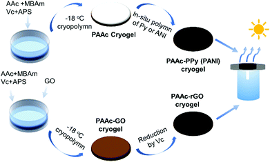 | ||
| Scheme 1 Preparation procedure for PAAc-PPy (PANI) or PAAc-GO (rGO) cryogel and the assembly of the photothermal evaporation system. | ||
3.2 Porous morphology of the cryogels and the distribution of the photothermal component
The real density of individual components in the composite cryogel (ρ0) and the apparent density of the cryogel/hydrogel (ρapp) are listed in Table S1 (ESI†). According to eqn (3), the porosity in volume fraction (ϕ) is obtained and also summarized in Table S1 (ESI†). All the cryogels have low apparent density (0.136–0.171 g cm−3) and high porosity (86–89 vol%), which effectively helps water transport and lessens heat loss. On the contrary, the PAAc hydrogel has higher density (0.360 g cm−3) and lower porosity fraction (70 vol%), which limits rapid water transport inside the PAAc hydrogel. As shown in Fig. S5 (ESI†), the porosity of the cryogel and hydrogel tested by the mercury porosimeter is consistent with the results obtained by density calculation. The total area per unit mass of the cryogel is more than ten times that of the hydrogel.TFSEM was used to observe the pore morphology of different cryogels with regard to the PAAc hydrogel and their images are shown in Fig. 1. From Fig. 1a, open macro-pores are not significantly observed for the PAAc hydrogel and some bulb-like pores are present in the inset with high magnification. As suggested by Fig. 1b–f, all the cryogels contrarily exhibit the macroporous morphology and the pores are open and interconnected, which is important for easy water transport inside the cryogels. As for the pure PAAc cryogel, the macropores are more and the pore-wall is thin. After the polymerization of ANI or Py inside the PAAc cryogel, the pore-wall of both the PAAc-ANI and PAAc-PPy cryogels becomes much thicker and the macropores seem to reduce, as seen in Fig. 1c and d, suggesting that the formed PANI and PPy are tightly and uniformly attached onto the pore-wall. SEM coupled with EDX was used to further confirm the uniform distribution of PANI and PPy inside the cryogels, as shown in Fig. S6 and S7 (ESI†), the element mapping images of the PAAc-ANI and PAAc-PPy cryogels, respectively. The images of C, O, and N elements reveal the same pattern from vertical and lateral viewing.
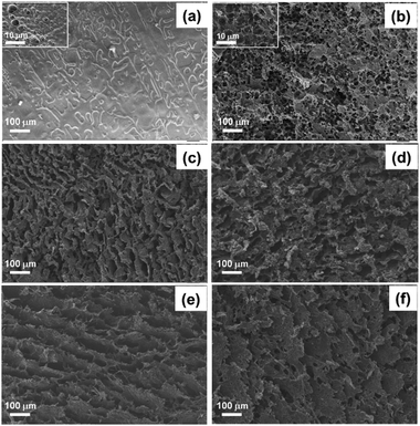 | ||
| Fig. 1 TFSEM images of the PAAc hydrogel (a) and the cryogels of PAAc (b), PAAc-PANI (c), PAAc-PPy (d), PAAc-GO (e), and PAAc-rGO (f). | ||
As indicated in Fig. 1e and f, the PAAc-GO and PAAc-rGO cryogels display lamellar-like macroporous morphology, induced by the presence of graphene nano-sheets. Compared to other cryogels, their macropores are much larger and the pore-walls are loosely piled up.
The uniform distribution of photothermal materials inside the cryogels is indirectly supported by FTIR and TGA analysis. As indicated by the local FTIR spectra (Fig. S8, ESI†), the signal of C![[double bond, length as m-dash]](https://www.rsc.org/images/entities/char_e001.gif) O stretching vibration for the composite cryogels displays a red-shift to a different extent, which follows the sequence PAAc-PPy > PAAc-PANI > PAAc-GO > PAAc-rGO. This red-shift is caused by hydrogen bonding between the carboxylic group of PAAc and the polar groups of the photothermal components. Also, the signal of C–O stretching vibration of COOH identifies the above interaction. This signal is present at ∼1252 cm−1 in the FTIR spectra of PAAc, PAAc-GO, and PAAc-rGO cryogels, with distinguishable red-shift for the PAAc-PANI cryogel (1242 cm−1) due to acidic doping. This signal is absent for the PAAc-PPy cryogel, suggesting that the acid doping of PPy by PAAc is much extensive. Such a strong interaction also causes a difference in the TGA thermogram between the PAAc-PPy cryogel and others (Fig. S4b, ESI†).
O stretching vibration for the composite cryogels displays a red-shift to a different extent, which follows the sequence PAAc-PPy > PAAc-PANI > PAAc-GO > PAAc-rGO. This red-shift is caused by hydrogen bonding between the carboxylic group of PAAc and the polar groups of the photothermal components. Also, the signal of C–O stretching vibration of COOH identifies the above interaction. This signal is present at ∼1252 cm−1 in the FTIR spectra of PAAc, PAAc-GO, and PAAc-rGO cryogels, with distinguishable red-shift for the PAAc-PANI cryogel (1242 cm−1) due to acidic doping. This signal is absent for the PAAc-PPy cryogel, suggesting that the acid doping of PPy by PAAc is much extensive. Such a strong interaction also causes a difference in the TGA thermogram between the PAAc-PPy cryogel and others (Fig. S4b, ESI†).
3.3 Light absorption, thermal insulation, and water uptake of different cryogels
While the π-conjugated structure of the photothermal materials facilitates sunlight absorbance over a widespread spectrum,10 the photothermal systems should eliminate the light transmittance and reflection. Thus, UV-vis-NIR reflectance and transmittance spectroscopy was used to evaluate sunlight absorbance, as demonstrated in Fig. 2.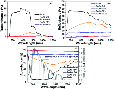 | ||
| Fig. 2 UV-vis-NIR transmittance (a), reflectance (b), and absorbance (c, left Y-axis) spectra of different cryogels, and solar spectral radiance (c, right Y-axis). | ||
The transmittance and reflectance of the PAAc cryogel in the wavelength range of 300–1400 nm is very high up to 17 and 76%, respectively. As shown in Fig. 2a, after introducing photothermal materials, the transmittance of the PAAc-GO cryogel drops below 4% and others are nearly zero in the whole spectrum. Meanwhile, the reflectance of the PAAc composite cryogels (Fig. 2b) decreases significantly compared with the PAAc cryogel. The reflectance decrease for the PAAc-GO cryogel is the weakest with the reflectance above 20% due to its lamellar morphology. After GO is reduced, the reflectance of the PAAc-rGO cryogel falls to about 17% in the visible/near-infrared region. Both the PAAc-PPy and PAAc-PANI cryogels have reflectance less than 5%. Therefore, compared with sunlight absorption by the PAAc cryogel (less than 60%, especially as low as 8% in the visible region) in Fig. 2c, composite cryogels with photothermal materials show a significant increase in sunlight absorption, especially for the PAAc-PPy and PAAc-PANI cryogels. It should be mentioned that the sunlight absorbance of the PAAc-PPy cryogel is almost 100% in the whole spectrum and the light intensity in the visible region is much higher as indicated by the solar spectral radiance. Based on the intensity distribution of sunlight over wavelength, the overall efficiency of sunlight absorption (ηabs) by different cryogels are calculated in the range of 200–2000 nm according to eqn (4) and the results are listed in Table S2 (ESI†).
 | (4) |
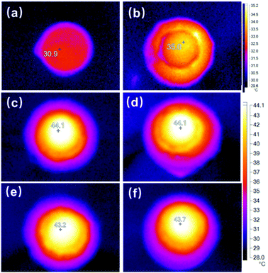
The sunlight absorption absolutely increases the cryogel temperature due to solar-to-heat conversion. Fig. S9 (ESI†) shows the IR camera images of different dry cryogels after one-sun irradiation for 20 min. The maximum temperature inside the light spot (Tmax) is as high as about 86.7 and 89.1 °C for the PAAc-PPy and PAAc-PANI cryogels. The maximum temperature of dry PAAc-GO and PAAc-rGO reaches 78.2 and 76.1 °C, respectively. However, the maximum temperature of the pure PAAc cryogel is much lower (35.3 °C), reflecting that photothermal materials prompt sunlight absorption. Fig. 3 offers the temperature outlook during the steady photothermal evaporation of pure water in different cases after one-sun irradiation for 20 min. Since there exists temperature inhomogeneity over the cryogel surface under irradiation, as indicated in Fig. 3, the average temperature over the cryogel sheet (Tave) under one-sun irradiation has been calculated. The temperature difference between the cryogel sheet and water reservoir is taken as (Tave − Troom). All the temperature data are summarized in Table S2 (ESI†).
Without any cryogel, the surface temperature of pure water can reach only 30.9 °C (Fig. 3a), while that of the PAAc cryogel sheet can get to 35 °C (Fig. 3b), which is close to that of the dried PAAc cryogel. On the other hand, with the incorporation of photothermal materials, the surface temperature of the cryogel sheet during photothermal evaporation exceeds 43 °C for all the composite cryogels and the elevated temperatures are much lower than those for dried cryogels, confirming that the light energy absorbed by photothermal materials is mostly consumed for water evaporation. It should be noted that the surface temperature of the photothermal system has two opposite influences on water evaporation. One is the less evaporation enthalpy of water at higher temperature, which prompts water evaporation. Another is the less heat loss from cryogels to the environment at lower temperature.
A photothermal evaporation system should require low thermal conductivity to prevent heat transfer to the surrounding environment and water reservoir. The thermal conductivity was determined to be 0.177, 0.056, 0.049, 0.043, and 0.038 W m−1 K−1 for the PAAc-PPy, PAAc-PANI, PAAc-GO, PAAc-rGO, and PAAc cryogels, respectively. These values are much lower than that of water (0.592 W m−1 K−1 at standard state) and comparable to that of the PS foam (∼0.043 W m−1 K−1). The excellent thermal insulation of all the cryogels can effectively minimize heat loss. Considering a little higher thermal conductivity of the PAAc-PPy cryogel, all the composite cryogel sheets are mounted on the mushroom-shaped PAAc cryogel substrate to further eliminate heat transfer and maintain the same evaporation conditions.
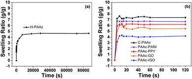
Water uptake by cryogels and water transport inside the cryogels are also important to achieve excellent photothermal evaporation. Thus, the water absorption behaviors of the PAAc hydrogel and different cryogels were compared through swelling kinetics study, as shown in Fig. 4a.
It takes about 4 h for the PAAc hydrogel (H-PAAc) to reach swelling equilibrium and the swelling ratio is about 4.6 g g−1. On the contrary, all the cryogels reach swelling equilibrium within 10 s and the swelling ratio of the PAAc cryogel (C-PAAc) is about 7.3 g g−1, as shown in Fig. 4b. To verify the capillary action, a rectangular sheet of the PAAc cryogel or hydrogel (1 cm × 6 cm) was used to absorb a thinned solution of red ink, as recorded in Video S1 and S2 (ESI†), respectively. It is seen that the cryogel transfers red ink to the uppermost end in only 25 s while the hydrogel transfers only 0.5 cm after 120 s. The rapid water uptake of the cryogels and the speedy transport of water inside the cryogels is attributed to their interconnected and hierarchical macroporosity. Later, a comparison of the photothermal evaporation of pure water between the PAAc hydrogel and cryogel as the substrates provides additional support.
3.4 Photothermal evaporation of pure water with different cryogels and energy consideration
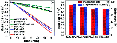
To evaluate the photothermal evaporation performance of cryogels, a mushroom-shaped PAAc cryogel was used as a pedestal covered with one composite cryogel sheet. Although the apparent density of each cryogel is lower than water, the completely swollen cryogels are still unable to self-float on water. In addition, elevated temperature from sunlight absorption might bring out the heat loss. Therefore, all the tested cryogels are entrapped in the PSt foam with the mushroom tip keeping in touch with the water reservoir (Scheme S1 and Fig. S1b, ESI†).The steady photothermal evaporation of pure water without and with the cryogels is shown in Fig. 5a. In the dark, the evaporation rate of pure water is 0.350 kg m−2 h−1. Under one-sun irradiation, the evaporation rate of pure water without and with the pure PAAc cryogel is almost the same (0.553 and 0.555 kg m−2 h−1, respectively). This result proposes that the PAAc cryogel does not affect the water transport and evaporation. After a composite cryogel sheet is used, the evaporation rate increases significantly by more than three folds. The PAAc-PPy cryogel has the highest rate (1.819 kg m−2 h−1), the PAAc-PANI cryogel stands next (1.678 kg m−2 h−1), while the PAAc-rGO and PAAc-GO cryogels have a similar evaporation rate, which were 1.585 and 1.551 kg m−2 h−1, respectively.
During steady photothermal evaporation, the incident sunlight is absorbed by the composite cryogel sheet and the absorbed solar energy is converted into heat to accelerate water evaporation. According to the UV-vis-NIR absorbance spectrum (Fig. 2c), both the PPAc-PPy and PAAc-PANI cryogels have almost 100% absorption of incident light but the absorption percent of both the PAAc-GO and PAAc-rGO cryogels is relatively low. Thus, the high evaporation rate for the PAAc-PPy and PAAc-PANI cryogels could be assigned to their efficient ability of sunlight absorption. Considering that PPAc-PPy and PAAc-PANI cryogels have similar sunlight absorption efficiency but different evaporation rate and that the PAAc-GO cryogel has lower light absorption efficiency than the PAAc-rGO cryogel but their evaporation rates are fairly close, there are other factors influencing the photothermal evaporation rate.
Within a certain period, the absorbed sunlight energy (Iabs) during steady photothermal evaporation is consumed by water-to-vapor conversion (Qevp = Rreal × ΔHevap), heating evaporated water from room temperature to the temperature of the cryogel sheet (Qheating,water = Cwater × ΔT) and possible heat loss (Qloss), as indicated by the following equations based on the energy balance.
| ηabsIinc = Iabs = Rreal × (ΔHevap + Cwater × ΔT) + Qloss | (5) |
| Rreal = Rlight − Rdark | (6) |
As proposed by the literature,24,45 there are three states of water molecules in the composite cryogel, namely, free water, transitional water, and bound water. Molecules of free water are connected with each other through hydrogen bonds and confined in dynamic and stable clusters, making water evaporation more difficult. Since there are still hydrogen bonds and other interactions between water molecules and the cryogel pore-wall, the molecules of bound water are also confined and difficult to evaporate. As for transitional water, water molecules are loosely confined and more likely to escape from the water cluster and the cryogel network. Therefore, the matrix as well as the photothermal material should be delicately chosen to balance the interactions of water-to-water and water-to-matrix, which could lessen the real evaporation enthalpy of water.
Because of the very low thermal conductivity of cryogels and the entrapping of the cryogel sheet inside the PSt foam, the heat loss (Qloss) in eqn (5) is neglected. Thus, ηevap and the total evaporation efficiency (ηtotal) are calculated according to the following equations.
 | (7) |
 | (8) |
3.5 Photothermal evaporation of pure water and water transport consideration
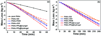
As discussed beforehand, PAAc cryogels have excellent ability to transport water due to their high hydrophilicity and hierarchical porosity. Excellent water transport ensures instant supply from the water reservoir to cover the evaporated water in the composite cryogel sheet, especially in the case of high evaporation rate. Therefore, photothermal evaporation under four-sun irradiation has also been performed with composite cryogel sheets and mushroom-shaped PAAc substrates. Upon light irradiation, water mass loss was immediately recorded. Fig. 6 shows the variation in the mass loss versus time within 1 h. In the first 10 min, all the cases exhibit a slower mass loss because the absorbed light energy is partially consumed to heat the cryogel sheet. After 20 min, photothermal evaporation goes steady for all the cryogel sheets and the evaporation rate within 20–60 min was determined to be 6.492, 5.663, 5.652, and 5.407 kg m−2 h−1 for the PAAc-PPy, PAAc-PANI, PAAc-rGO, and PAAc-GO cryogel sheets, respectively. With mushroom-shaped PAAc cryogel as the substrate, water transport inside is sufficiently high to satisfy surficial water evaporation. After the replacement of the substrate with the PAAc hydrogel, the water mass loss behaviors differ, as suggested by the hollow data points of the PAAc-PPy@hydrogel. From 40 min, the fitting line slopes up, indicating the decrease in the evaporation rate. Based on the slopes within 20–40 min and 40–60 min, the average evaporation rate in the related duration is 4.871 and 2.962 kg m−2 h−1, respectively. This result is caused by the slow water transport inside the PAAc hydrogel, leading to the shortage of water in the PAAc-PPy cryogel sheet. It can be observed that the PAAc-PPy cryogel sheet starts to distort at 40 min and finally becomes warped, as shown in Fig. S10a (ESI†). The surplus heat has to increase the temperature of the PAAc-PPy cryogel sheet. After being irradiated with four-sun light for 1 h, Tave and Tmax for the PAAc-PPy@cryogel remains 57.0 and 60.1 °C, respectively. However, due to insufficient water supply when the hydrogel is used as the substrate, the light-to-vapor conversion cannot happen smoothly and the light energy absorbed by the photothermal layer is mostly converted into heat. Tave and Tmax for the PAAc-PPy@hydrogel increases to 150.0 and 174.7 °C, respectively. All the data are shown in Table S5 (ESI†).Long-term photothermal evaporation has been carried out under one-sun irradiation for 4 h. The mushroom-shaped PAAc cryogel and the composite cryogel sheet were assembled and the starting point was taken as that upon light irradiation. The results are demonstrated as solid points in Fig. 6b. Over a duration of 4 h, the fitting lines seems linear for the PAAc cryogel, indicating the constant evaporation rate and sufficient water transport inside the PAAc cryogel. Also, the PAAc-PPy cryogel sheet has the highest evaporation rate and PAAc-GO the lowest. The situation is different when the mushroom-shaped PAAc hydrogel instead of the PAAc cryogel is used as the substrate. As shown with hollow points with dotted line for the PAAc-PPy@hydrogel, the evaporation rate begins to significantly decrease at 150 min. During the first half an hour (0–30 min), the evaporation rate for obviously PAAc-PPy@hydrogel (1.483 kg m−2 h−1) is comparable with that for obviously PAAc-PPy@cryogel (1.587 kg m−2 h−1). During the second half an hour (30–60 min), the evaporation rate for both the cases is a little different (1.627 kg m−2 h−1 for obviously hydrogel vs. 1.833 kg m−2 h−1 for the cryogel). The large deviation occurs within 150–180 min, where the evaporation rate is 1.748 and 1.186 kg m−2 h−1 for the PAAc-PPy@cryogel and PPy@hydrogel, respectively. The continuous decline of the evaporation rate is caused by the low water transport inside the PAAc hydrogel substrate. As shown in Fig. S10b (ESI†), the PAAc-PPy cryogel sheet at the top of the hydrogel substrate becomes short of water and dehydration makes the sheet gradually warp upwards. At the same time, the surface temperature of different cryogel sheets was measured every half an hour and the average values are demonstrated in Fig. S11a (ESI†). After 30 min, the temperatures for all the cryogel cases quickly rise to a level-off value with the highest for the PAAc-PPy@cryogel. Extraordinarily, the temperature of the PAAc-PPy@hydrogel rises to 45.3 °C at 150 min, then keeps increasing up to 67.2 °C at 240 min. In spite of the temperature increase in this case, the evaporation rate drops noticeably after 120 min (Fig. S11b, ESI†).
Based on the above evaporation results, it is established that the PAAc cryogel as the substrate could efficiently transport water from the water reservoir to the evaporation sheet surface, while the PAAc hydrogel failed. The morphology observation by SEM, the measurement of the swelling rate, and the capillary test provide credible supports.
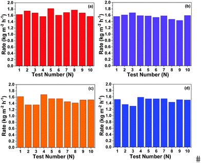
To clarify the long-term durability and reusability of the current photothermal evaporation system, different composite cryogel sheets and mushroom-shaped PAAc cryogel substrates have been assembled to test photothermal evaporation within three months. Each test was performed occasionally and the recorded durations were accidentally chosen. Fig. 7a–d show the results of ten tests for four composite cryogel sheets with the mushroom-shaped PAAc cryogel substrate. All the photothermal evaporation systems maintain a high evaporation rate.
3.6 Photothermal evaporation of salt water with different cryogels
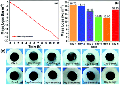
To evaluate the application of cryogels in seawater desalination, simulated seawater (3.0 × 10⁴ mg L−1 Na+, 3.5 × 10³ mg L−1 Mg2+, and 1.76 × 10³ mg L−1 K+) was used as the water reservoir to perform photothermal evaporation with the PAAc-PPy cryogel sheet and the PAAc cryogel substrate. Under one-sun irradiation, photothermal evaporation lasted for 12 h. Then, the light was turned off and the tip of the mushroom-shaped cryogel maintained the same status for another 12 h. Afterwards, this procedure was repeated in the following 4 days to follow the mass loss and salt precipitation on the cryogel sheet. Fig. 8a shows the mass loss at every one hour within the first day. Except an unreliable data point (at 10 h), others are in linear correlation. Within each one-hour duration, the mass loss lies in the range of 1.343–1.648 kg m−2 h−1 and the average evaporation rate in the first 12 h is 1.560 kg m−2 h−1, which is a little lower than that of pure water. The decrease in the vapor pressure of the solution compared with that of the pure solvent is responsible for this result. As shown in Fig. 8b, the mass loss of salty water reservoir in the following days keeps decreasing and exhibits a tendency of levelling-off at the fifth day. Considering water evaporation, the concentration of salty water keeps increasing, which is one reason for the further decrease in the evaporation rate. Another reason is the salting out during the evaporation, which might clog the pathway of water transport.The surface appearance of the PAAc-PPy cryogel sheet was recorded, as shown in Fig. 8c. The salt separated out on the surface keeps increasing in amount at the night in the beginning of each day. It hinders the solar light absorption and water volatilization, and thus the evaporation rate of water might be reduced. However, due to rapid water transport inside the PAAc cryogel, some salt was dissolved during the night, which is evidenced by the less salt on the surface the next morning. At 20:00 pm of the fifth day, the salt on the surface of the PAAc-PPy cryogel reached the maximum amount due to the edge-preferential crystallization.46 Very little salt was dissolved up to 8:00 am of the sixth day. The mass loss of the salty water reservoir during the fifth day dropped to 12.00 kg m−2, being 64% of that during the first day. Therefore, this PAAc-PPy cryogel sheet and the PAAc cryogel substrate were immersed in simulated seawater to wash out the salt solid. Then, photothermal evaporation experiment was continued for an additional 12 h. The cryogel surface looked neat without the salt solid both at morning and night beginning while the mass loss significantly increased to 16.25 kg m−2. In the practical performance of seawater desalination, the concentration of the seawater reservoir is constant, which is different from the increasing concentration of salty water reservoir in the current research. Thus, it is believed that the current photothermal evaporation system is convenient and efficient for seawater desalination.
With a self-made device (Fig. 9 right), photothermal evaporation of simulated seawater was performed under one-sun irradiation and the evaporated water was collected. As shown by the recorded video (ESI,† Video S3), water vapor was generated under light irradiation and gradually condensed on the collector top. The water drops flowed along the inner surface and accumulated at the bottom. ICP-MS was used to determine the ion concentration. The ion concentrations of simulated seawater were pretty high. After photothermal evaporation, the concentrations of these ions were reduced by at least 4 orders of magnitude, which was 0.015 mg L−1 for Na+, 0.102 mg L−1 for Mg2+, and 0.063 mg L−1 for K+ (Fig. 9). All the ions are far below the fresh water taste threshold defined by the World Health Organization (WHO).
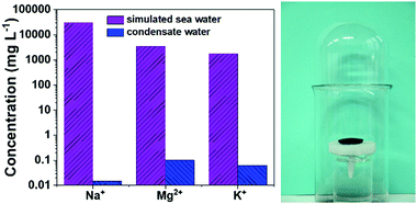 | ||
| Fig. 9 The concentrations of the three ions in simulated seawater before and after photothermal desalination (left) with a self-made vapor collection device (right). | ||
4. Conclusions
Through cryopolymerization, different PAAc cryogels with photothermal materials have been prepared to assemble photothermal evaporation systems with a composite cryogel sheet and a mushroom-shaped PAAc cryogel substrate. The hydrophilicity and hierarchical porosity facilitate rapid water absorption and efficient water transport compared with the PAAc hydrogel prepared at room temperature. The porous morphology is also helpful to lessen the heat loss. Due to the strong interaction between PAAc and the photothermal materials, composite cryogels with PPy, PANI, GO, and rGO exhibit uniform distribution of the photothermal materials inside the PAAc cryogel. Thus, the light absorbance of the composite cryogel sheet is almost 98% for the PAAc-PPy and PAAc-PANI cryogels. During steady photothermal evaporation under one-sun irradiation, the evaporation rate of pure water for the PAAc-PPy cryogel sheet can reach 1.819 kg m−2 h−1 with an evaporation efficiency of about 100% if the possible heat loss and the deviation of evaporation enthalpy are neglected. However, the abnormal efficiency of the PAAc-GO sheet suggests the uncertainty of such an assumption. Increasing the incident light to four-sun, the evaporation rate increases significantly for all composite cryogel sheets. The PAAc-PPy cryogel sheet still exhibits the highest evaporation (6.492 kg m−2 h−1) but after replacing the substrate with the PAAc hydrogel, its evaporation rate drops noticeably (2.962 kg m−2 h−1) due to the poor water transport of the PAAc hydrogel. All photothermal evaporation systems with the composite cryogel sheet and the PAAc cryogel substrate demonstrate long-term availability and reproducibility of photothermal evaporation under one-sun irradiation but the PPAc-PPy sheet with the PAAc hydrogel substrate displays slower evaporation. As for the photothermal evaporation of salty water with the PPAc-PPy sheet with the PAAc hydrogel substrate, the evaporation rate under one-sun reaches 1.560 kg m−2 h−1 within the first 12 h. The accumulated salt could be partially removed with renewed water through cryogel capillary and the performance was recovered by washing with salt water. The ion concentrations in condensed water reduced significantly. Therefore, the present PAAc cryogel is an excellent platform for photothermal evaporation to incorporate different active materials in water purification and seawater desalination.Author contributions
Wei-Dong He: conceptualization, methodology, formal analysis, writing – reviewing and editing, supervision. Jia-Yun Wang: investigation, data curation, writing – original draft. Xiao-Xiao Guo: validation, writing – reviewing. Jun Chen: formal analysis, visualization. Investigation – some experiments, validation. Hui-Juan Li: formal analysis, resource, investigation – some experiments. Abdul Haleem and Sheng-Qi Chen: writing – teviewing and editing.Conflicts of interest
There are no conflicts to declare.Acknowledgements
The authors are grateful for the financial support provided by National Natural Science Foundation of China (20934005 and 21274136), Chinese Academy of Sciences President's International Fellowship Initiative (2017VEA0031) and Natural Science Foundation of Anhui Province (1808085QE125). Abdul Haleem wishes to acknowledge Chinese Scholarship Council for his scholarship of PhD studies.References
- Y. Jiang, J. Environ. Manage., 2009, 90(11), 3185–3196 CrossRef PubMed.
- R. P. Schwarzenbach, T. Egli, T. B. Hofstetter, U. von Gunten and B. Wehrli, Annu. Rev. Environ. Resour., 2010, 35(1), 109–136 CrossRef.
- Q. Gan, T. Zhang, R. Chen, X. Wang and M. Ye, ACS. Sustainable Chem. Eng., 2019, 7(4), 3925–3932 CrossRef CAS.
- X. Wu, M. E. Robson, J. L. Phelps, J. S. Tan, B. Shao and G. Owens, et al. , Nano Energy, 2019, 56, 708–715 CrossRef CAS.
- Y. Xu, J. Ma, D. Liu, H. Xu, F. Cui and W. Wang, Chem. Eng. J., 2019, 356, 869–876 CrossRef CAS.
- V. Kashyap, A. Al-Bayati, S. M. Sajadi, P. Irajizad, S. H. Wang and H. Ghasemi, J. Mater. Chem. A, 2017, 5(29), 15227–15234 RSC.
- Y. Li, T. Gao, Z. Yang, C. Chen, W. Luo and J. Song, et al. , Adv. Mater., 2017, 29(26), 1700981 CrossRef PubMed.
- Y. Lin, H. Xu, X. Shan, Y. Di, A. Zhao and Y. Hu, et al. , J. Mater. Chem. A, 2019, 7(33), 19203–19227 RSC.
- G. Liu, J. Xu and K. Wang, Nano Energy, 2017, 41, 269–284 CrossRef CAS.
- M. Gao, L. Zhu, C. K. Peh and G. W. Ho, Energy Environ. Sci., 2019, 12(3), 841–864 RSC.
- B. Zhu, H. Kou, Z. Liu, Z. Wang, D. K. Macharia and M. Zhu, et al. , ACS. Appl. Mater. Interfaces, 2019, 11(38), 35005–35014 CrossRef CAS PubMed.
- X. Wu, T. Gao, C. Han, J. Xu, G. Owens and H. Xu, Sci. Bull., 2019, 64(21), 1625–1633 CrossRef CAS.
- F. Gong, W. Wang, H. Li, D. Xia, Q. Dai and X. Wu, et al. , Appl. Energy, 2020, 261, 114410 CrossRef CAS.
- H. Wang, A. Du, X. Ji, C. Zhang, B. Zhou and Z. Zhang, et al. , ACS. Appl. Mater. Interfaces, 2019, 11(45), 42057–42065 CrossRef CAS PubMed.
- W. Li, Z. Li, K. Bertelsmann and D. E. Fan, Adv. Mater., 2019, 31(29), e1900720 CrossRef PubMed.
- Q. Chen, Z. Pei, Y. Xu, Z. Li, Y. Yang and Y. Wei, et al. , Chem. Sci., 2018, 9(3), 623–628 RSC.
- Z. Wang, Y. Yan, X. Shen, C. Jin, Q. Sun and H. Li, J. Mater. Chem. A, 2019, 7(36), 20706–20712 RSC.
- W. Wang, J. Niu, J. Guo, L. Yin and H. Huang, Sol. Energy Mater. Sol. C, 2019, 201, 110046 CrossRef CAS.
- H.-Y. Zhao, J. Zhou, Z.-L. Yu, L.-F. Chen, H.-J. Zhan and H.-W. Zhu, et al. , Cell Rep. Phys. Sci., 2020, 1(6), 100074 CrossRef.
- Q. Wang, L. Qiu, Y. Jia, Y. Chang, X. Tan and L. Yang, et al. , Sol. Energy Mater. Sol. C, 2019, 202, 110116 CrossRef CAS.
- Y. Chen, Y. Shi, H. Kou, D. Liu, Y. Huang and Z. Chen, et al. , ACS Sustainable Chem. Eng., 2019, 7(3), 2911–2915 CrossRef CAS.
- D.-D. Qin, Y.-J. Zhu, F.-F. Chen, R.-L. Yang and Z.-C. Xiong, Carbon, 2019, 150, 233–243 CrossRef CAS.
- C. Zhang, B. Yuan, Y. Liang, L. Yang, L. Bai and H. Yang, et al. , Mater. Chem. Phys., 2021, 258, 123998 CrossRef CAS.
- F. Zhao, X. Zhou, Y. Shi, X. Qian, M. Alexander and X. Zhao, et al. , Nat. Nanotechnol., 2018, 13(6), 489–495 CrossRef CAS PubMed.
- D. Weng, F. Xu, X. Li, Y. Li and J. Sun, J. Mater. Chem. A, 2018, 6(47), 24441–24451 RSC.
- L. Zhu, M. Gao, C. K. N. Peh, X. Wang and G. W. Ho, Adv. Energy Mater., 2018, 8(16), 1702149 CrossRef.
- J. Hou, S. Liu, Y. Ning, Y. Wang, Y. Yang and Q. Wang, J. Alloys Compd., 2021, 851, 156879 CrossRef CAS.
- C. Xiao, W. Liang, Q.-M. Hasi, L. Chen, J. He and F. Liu, et al. , Mater. Today Energy, 2020, 16, 100417 CrossRef.
- B. Yuan, C. Zhang, Y. Liang, L. Yang, H. Yang and L. Bai, et al. , Adv. Sustainable Syst., 2020, 2000245 Search PubMed.
- N. Ma, Q. Fu, Y. Hong, X. Hao, X. Wang and J. Ju, et al. , ACS Appl. Mater. Interfaces, 2020, 12(15), 18165–18173 CrossRef CAS PubMed.
- Q. F. Guan, Z. M. Han, Z. C. Ling, H. B. Yang and S. H. Yu, Nano Lett., 2020, 5699–5704 CrossRef CAS PubMed.
- J. Tang, T. Zheng, Z. Song, Y. Shao, N. Li and K. Jia, et al. , ACS Appl. Mater. Interfaces, 2020, 12(16), 18504–18511 CrossRef CAS PubMed.
- M. Zhu, Y. Li, F. Chen, X. Zhu, J. Dai and Y. Li, et al. , Adv. Energy Mater., 2018, 8(4), 1701028 CrossRef.
- L. Shi, Y. Wang, L. Zhang and P. Wang, J. Mater. Chem. A, 2017, 5(31), 16212–16219 RSC.
- N. Xu, X. Hu, W. Xu, X. Li, L. Zhou and S. Zhu, et al. , Adv. Mater., 2017, 29(28), 1606762 CrossRef PubMed.
- H. Kou, Z. Liu, B. Zhu, D. K. Macharia, S. Ahmed and B. Wu, et al. , Desalination, 2019, 462, 29–38 CrossRef CAS.
- H. Huang, J. Yao, L. Li, F. Zhu, Z. Liu and X. Zeng, et al. , J. Mater. Sci., 2016, 51(18), 8728–8736 CrossRef CAS.
- Y. Wang, L. Zhang and P. Wang, ACS Sustainable Chem. Eng., 2016, 4(3), 1223–1230 CrossRef CAS.
- L. Zhang, B. Tang, J. Wu, R. Li and P. Wang, Adv. Mater., 2015, 27(33), 4889–4894 CrossRef CAS PubMed.
- C.-S. Hu, H.-J. Li, J.-Y. Wang, A. Haleem, X.-C. Li and M. Siddiq, et al. , ACS. Appl. Energy Mater., 2019, 2(10), 7554–7563 CrossRef CAS.
- K. D. V. Marcano and D. C. Berlin, et al. , ACS Nano, 2010, 4(8), 4806 CrossRef PubMed.
- N. Sahiner and F. Seven, Energy, 2014, 71, 170–179 CrossRef CAS.
- R. Sun, H. Chen, Q. Li, Q. Song and X. Zhang, Nanoscale, 2014, 6(21), 12912–12920 RSC.
- J. Zhang, H. Yang, G. Shen, P. Cheng, J. Zhang and S. Guo, Chem. Commun., 2010, 46(7), 1112–1114 RSC.
- Y. Guo, X. Zhao, F. Zhao, Z. Jiao, X. Zhou and G. Yu, Energy Environ. Sci., 2020, 13(7), 2087–2095 RSC.
- Y. Xia, Q. Hou, H. Jubaer, Y. Li, Y. Kang and S. Yuan, et al. , Energy Environ. Sci., 2019, 12(6), 1840–1847 RSC.
Footnote |
| † Electronic supplementary information (ESI) available. See DOI: 10.1039/d1ma00119a |
| This journal is © The Royal Society of Chemistry 2021 |

