 Open Access Article
Creative Commons Attribution 3.0 Unported Licence
Adsorbed xenon propellant storage: are nanoporous materials worth the weight?†
Melanie T.
Huynh
a,
Nickolas
Gantzler
b,
Samuel
Hough
a,
David
Roundy
 b,
Praveen K.
Thallapally
 c and
Cory M.
Simon
 *a
*a
aSchool of Chemical, Biological, and Environmental Engineering, Oregon State University, Corvallis, OR, USA. E-mail: Cory.Simon@oregonstate.edu
bDepartment of Physics, Oregon State University, Corvallis, OR, USA
cPacific Northwest National Laboratory, Richland, WA, USA
First published on 13th May 2021
Abstract
Xenon is used as a propellant for spacecraft. Conventionally, xenon is compressed to high pressures (75–300 bar) for bulk storage onboard the spacecraft. An adsorbed xenon storage system based on nanoporous materials (NPMs) could, potentially, (i) reduce the storage pressures, (ii) allow for thinner-walled and lighter pressure vessels, and (iii) if the NPM itself is sufficiently light, reduce the overall mass of the storage system and, thus, of the payload of the rocket launch. To investigate, we develop a simple mathematical model of an adsorbed xenon storage system by coupling a mechanical model for the pressure vessel and a thermodynamic model for the density of xenon adsorbed in the NPM. From the model, we derive the optimal storage pressure, tailored to each NPM, with the objective of minimizing the mass of the materials (walls of the pressure vessel + NPM) required to store the xenon. The model enables us to: (i) rank NPMs for adsorbed xenon propellant storage, (ii) compare adsorbed storage to the baseline of bulk storage, and (iii) understand what properties of NPMs are desirable for adsorbed xenon propellant storage. We use the model to evaluate several NPMs, mostly metal–organic frameworks (MOFs), for adsorbed xenon propellant storage at room temperature, using experimental xenon adsorption data as input. We find Ni-MOF-74 and MOF-505 outperform activated carbon, a traditional adsorbent. However, each optimized adsorbed xenon storage system is heavier than the optimized bulk storage system, owing dominantly to the large mass of the NPM itself. To provide a lighter adsorbed xenon storage system than a bulk storage system, our model suggests to pursue light adsorbents with a high gravimetric saturation loading of xenon.
1 Introduction
Ion thrusters are used to propel spacecraft and satellites.1,2 Xenon is commonly used as a propellant owing to its inertness, high molecular weight, and relatively low ionization energy.3To store xenon propellant onboard the spacecraft, xenon is typically compressed and stored at high pressures (75–300 bar)4–7 between 20 °C and 50 °C, in a supercritical state.8 The pressure vessel must have thick walls to safely contain the xenon at these high pressures, making it heavy. Because the cost of launching a payload into Earths orbit is ca. 10![[thin space (1/6-em)]](https://www.rsc.org/images/entities/char_2009.gif) 000 USD per lb,9 it is desirable to reduce the mass of storage materials required to store xenon propellant onboard spacecraft.
000 USD per lb,9 it is desirable to reduce the mass of storage materials required to store xenon propellant onboard spacecraft.
We investigate the feasibility of an alternative xenon storage strategy, with the objective of reducing the mass of the storage materials required to carry the xenon propellant into space: packing the pressure vessel with a porous adsorbent material to help densify the xenon (i.e., use an adsorbent in combination with pressurization). Activated carbon has been investigated for adsorbed xenon propellant storage, but it does not reduce the mass of the storage system.10 Newer classes of nanoporous materials, such as metal–organic frameworks (MOFs),11 porous organic cages (POCs),12 and covalent organic frameworks (COFs),13 exhibit very high internal surface areas14,15 and have demonstrated promise for gas densification in the context of vehicular hydrogen and methane storage,16 motivating us to consider these advanced nanoporous materials for adsorbed xenon propellant storage. Moreover, several of these nanoporous materials exhibit a high affinity for xenon, evidenced by their adsorptive selectivity for xenon in the context of separations.17–20
Herein, we develop a simple mathematical model of an adsorbed xenon propellant storage system by coupling a mechanical stress model for the pressure vessel and a thermodynamic model for gas adsorption in the nanoporous material. This model enables us to evaluate and rank adsorbents for adsorbed xenon propellant storage. The performance of each adsorbed storage system is judged by the mass of storage materials – composed of the walls of the pressure vessel and the mass of the adsorbent material – required to carry the xenon propellant needed for the mission. We use our model to find the optimal storage pressure, tailored to each nanoporous material, that minimizes the mass of the storage materials needed. Conventional, bulk xenon storage serves as a baseline for evaluating porous materials for adsorbed xenon storage. Thus, we also use our model to find the minimal-mass pressure vessel under a bulk storage strategy. Our hypothesis is that the optimal storage pressure for an adsorbed xenon storage systems is lower than that of the bulk xenon storage system, thereby allowing for thinner-walled and thus lighter pressure vessels in the adsorbed storage system. The important question our model addresses is whether the reduced mass of the pressure vessel in the adsorbed xenon system compensates for the (additional) mass of the adsorbent required to store the xenon at a lower pressure. The answer to this question depends on the xenon adsorption isotherm in and density of the nanoporous material.
We use our model to assess several nanoporous materials for xenon propellant storage, using experimentally reported xenon adsorption isotherms as input. We find that MOF-505 and Ni-MOF-74 outperform the traditional adsorbent, activated carbon. However, when comparing the adsorbed and bulk xenon storage systems, we find that none of the nanoporous materials considered compete with the bulk storage system in terms of reducing the overall mass of the storage system. On the basis of a strong relationship between the adsorbent performance and its xenon adsorption properties, our model suggests the saturation loading of xenon in the adsorbent must exceed ca. 94 mmol Xe g−1 for the adsorbed storage system to be lighter than the bulk storage system. Also, nanoporous materials that exhibit high gravimetric surface areas tend to perform well for adsorbed xenon storage. Our conclusions rest on several simplifying assumptions, which we clearly list and discuss.
2 Modeling the pressure vessel, bulk xenon density, and xenon adsorption in the adsorbent
In this section, we formulate the mathematical models we use to describe the pressure vessel, bulk xenon gas, and xenon adsorption in the adsorbent. We later couple these models together to compose our models of both a bulk and adsorbed xenon propellant storage system. Table 1 summarizes the parameters and variables in our model.2.1 The pressure vessel: spherical and thin-walled
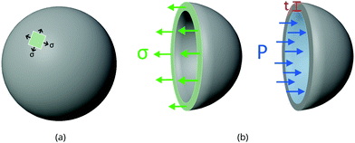
Take the pressure vessel storing the xenon, in either the bulk or adsorbed phase, as a spherical shell composed of a homogeneous, elastic material. Let r [m] be the inner radius of the shell and t [m] be the (uniform) thickness of the vessel walls. Here, we relate the pressure P [bar] of (bulk or adsorbed) xenon inside the vessel to the resulting circumferential stress σ [bar] internal to the material composing the vessel walls. We use this relation to set the thickness of the walls of the vessel to safely contain the xenon without rupturing.By invoking the thin wall approximation,21 assuming r ≫ t, (i) the circumferential stress σ is spatially uniform in the material and (ii) we do not distinguish between the inner and outer radius r. A free body diagram on a hemisphere of the vessel (see Fig. 1) balances two opposing forces in the direction normal to the plane on which the hemisphere sits, arising from: (a) the circumferential stress in the material and (b) the pressure of the gas on the inner walls, giving:
| Pπr2 = σ2πrt. | (1) |
 | (2) |
2.2 Density of bulk xenon fluid: interpolation of NIST data
We interpolate data from the NIST Chemistry WebBook26 to characterize the density of bulk xenon gas, ρXe [mol m−3], as a function of pressure, P, at constant temperature, T = 298 K. Fig. 2 displays ρXe = ρXe(P;T). Note that 298 K is above the critical temperature of xenon (Tc = 289.74 K). Near the critical pressure of xenon (Pc = 58.42 bar), small changes in pressure result in large changes in density.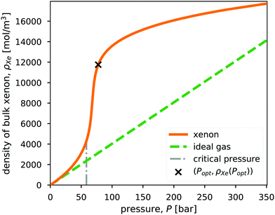 | ||
| Fig. 2 The density of xenon, ρXe = ρXe(P), as a function of pressure, P, at a fixed temperature of 298 K, taken from NIST.26 For comparison, the density of the ideal gas is also shown. The vertical, dashed line marks the critical pressure of xenon (Pc = 58.42 bar. Note Tc = 289.74 K.). The x marks the optimal storage conditions in a bulk xenon propellant storage system, which we will derive later. | ||
For comparison, we also show the density of the ideal gas in Fig. 2. The ideal gas law is not sufficiently accurate for describing the density of xenon at high pressures relevant to propellant storage. As a result of attractions between the xenon particles, the xenon fluid exhibits a higher density than the ideal gas in the pressure range shown in Fig. 2.
2.3 Density of adsorbed xenon: the Langmuir adsorption model
To describe the density of adsorbed xenon in a porous material, ρadsXe [mol m−3], as a function of pressure and at fixed temperature, we use Langmuir's single-site equilibrium adsorption model:27 | (3) |
For the purposes of modeling adsorbed xenon storage, under the single-site Langmuir model, a porous material is fully characterized by M, K and ρads. Volumetric (ρadsXe) and gravimetric (ρadsXe/ρads) xenon adsorption in the material, both of which are important for xenon propellant storage, are related by ρads.
For each adsorbent material under consideration:
• We identify its Langmuir model parameters K and M from its experimentally measured, gravimetric xenon adsorption isotherm [mol Xe kg−1 adsorbent] in a least-squares fitting routine. As opposed to constructing ρadsXe(P) by interpolating the data, the Langmuir model allows us to extrapolate the adsorbed density to larger pressures than observed in the experiments (ca. 0–1 bar).
• We approximate the bulk density ρads of each nanoporous material as equal to its crystal density. We revisit this assumption later for materials with reported bulk densities.28 The bulk density depends on the form of the material (powder, pellet, etc.)29–31 but is typically less than the crystal density owing to interstitial voids.28
| Symbol | Description | Units |
|---|---|---|
| n Xe | Moles of xenon required for mission | mol |
| P | Pressure of xenon gas in the bulk- or adsorbed-storage vessel | bar |
| ρ Xe | Density of xenon gas in the bulk phase | mol m−3 |
| ρ adsXe | Density of xenon gas in the adsorbent (absolute adsorption) | mol m−3 |
| K | Langmuir parameter: describes xenon-adsorbent affinity | bar−1 |
| M | Langmuir parameter: saturation loading of xenon in the adsorbent | mol kg−1 |
| ρ ads | Bulk density of the (empty) adsorbent | kg m−3 |
| ρ v | Density of the material composing the vessel walls | kg m−3 |
| σ y | Yield strength of material composing the vessel walls | bar |
| m v | Mass of material composing the vessel walls | kg |
| m ads | Mass of adsorbent filling the vessel | kg |
| w Xe | Molar mass of xenon | kg mol−1 |
3 Xenon storage
We now couple the models for the xenon fluid, pressure vessel, and adsorbent to formulate a model for both bulk- and adsorbed-xenon storage systems. For both storage strategies, our first goal is to determine the mass of storage materials– the mass of material composing the walls of the pressure vessel and, if adsorbed-xenon storage, the mass of the adsorbent material– needed to carry the nXe [mol] of xenon required for the mission. The mass of storage materials required is a function of our choice of storage pressure. Our second goal is to then find the storage pressure, for both bulk- and adsorbed-xenon propellant storage systems, that minimizes the mass of storage materials. The primary performance metric of a given xenon propellant storage system is the tankage fraction: the mass of storage materials required per mass of xenon propellant stored.253.1 Bulk xenon propellant storage
In bulk xenon storage, we compress the pure xenon fluid and contain it in a free-space, spherical pressure vessel.The volume of the vessel required‡ to store the nXe [mol] of xenon is nXe/ρXe. Thus, the radius of the spherical vessel as a function of storage pressure is:
 | (4) |
 | (5) |
 | (6) |
 | (7) |
3.2 Adsorbed xenon propellant storage
In adsorbed xenon storage, we fully pack the spherical pressure vessel with porous material to store xenon gas in the adsorbed phase.The mass of adsorbent mads needed for the mission, as a function of storage pressure, P, is
 | (8) |
 | (9) |
The required thickness of the vessel walls, t = t(P), follows from substituting r(P) into the stress model for the vessel in eqn (2). Finally, the mass of material composing the walls of the pressure vessel is:
 | (10) |
 | (11) |
Finally, the minimal mass of storage materials required for the mission is mads(Popt) + mv(Popt). The optimal tankage fraction is then:
 | (12) |
• the material composing the vessel walls to be light (small ρv) and strong (large σy).
• the adsorbent material to be light (small ρads), strongly adsorb xenon (large K), and have a large number of xenon adsorption sites packed per volume (large Mρads).
While these effects of material parameters on the tankage fraction are qualitatively unsurprising, eqn (12) allows us to quantitatively evaluate several adsorbents for adsorbed xenon propellant storage and compare to the bulk storage strategy.
3.3 Remarks
Conveniently, the optimal storage pressure and tankage fraction do not depend on the amount of xenon required for the mission, nXe, for both bulk and adsorbed storage systems (see eqn (5) and (7) and eqn (11) and (12), respectively). However, the choice of the safety factor β could affect (i) the ranking of adsorbents according to their optimal tankage fractions (see eqn (12)) and (ii) the ratio of the bulk to adsorbed optimal tankage fractions (divide eqn (7) by eqn (12)).While eqn (12) shows the effects of material parameters on the optimal tankage fraction, these material parameters are intimately coupled and correlated, and therefore generally cannot be independently tuned. E.g., denser materials tend to more strongly attract xenon, giving rise to a positive correlation between ρads and K.
4 Results
We now evaluate several porous materials for adsorbed xenon propellant storage, with bulk xenon storage as a baseline. The data and Julia code to fully reproduce our calculations and plots are available at http://github.com/SimonEnsemble/PropellantStorage.Without loss of generalization, we take the required mass of propellant needed for the mission as nXewXe = 100 kg.
4.1 Compressed, bulk xenon storage
As a baseline, we first analyze a bulk xenon storage system, where xenon gas is compressed and stored in a spherical, thin-walled pressure vessel, without an adsorbent.
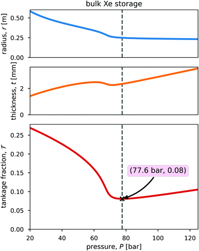
Fig. 3 shows the radius, wall thickness, and tankage fraction for bulk xenon storage over a pressure range of 20 bar to 125 bar. The optimal storage pressure is Popt = 77.6 bar, which provides a minimal tankage fraction of  = 0.08. Notably, Popt > Pc to exploit the large slope of ρXe(P) in Fig. 2, where a small change in pressure results in a large change in xenon density. See the x in Fig. 2 that marks (Popt,ρXe(Popt)).
4.2 Adsorbed xenon storage
Next, we evaluate and compare the performance of several porous materials for adsorbed xenon propellant storage, with the bulk storage system as a baseline.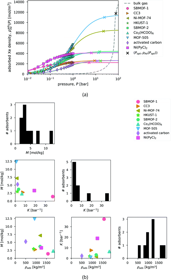 | ||
| Fig. 5 Xenon adsorption in the candidate adsorbents. (a) Curves show the fitted Langmuir adsorption model, ρadsXe(P) in eqn (3), to describe the adsorbed xenon density in each adsorbent at 298 K. Points show the experimentally measured xenon adsorption isotherms (at 298 K, except for MOF-505, 292 K, and Ni-MOF-74, 297 K), converted from the raw gravimetric adsorption data using ρads. The dashed curve shows the density of the bulk gas, ρXe(P). The x's mark the optimal storage conditions (Popt,ρadsXe(Popt)) that we will derive later. (b) The distributions (diagonal) and correlations between (off-diagonal) the Langmuir M, Langmuir K, and density ρads of the adsorbents. | ||
Although xenon adsorption data was also available for IRMOF-146 and PCN-12,42 we omit these MOFs from our analysis because their xenon adsorption isotherms do not exhibit a plateau, preventing reliable estimation of M to extrapolate the adsorbed xenon density beyond the maximum pressure observed in the data, ca. 1 bar.
To summarize the properties of the adsorbents that dictate their performance for adsorbed xenon propellant storage, Fig. 5b displays the distributions and correlations between the adsorbent parameters K, M, and ρads.
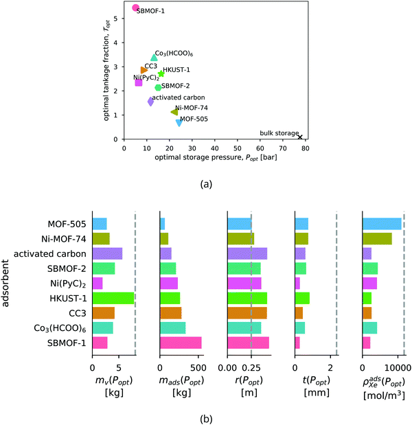
Ranking the adsorbents. The adsorbents in Fig. 6b are ranked by the optimal tankage fraction. Ni-MOF-74 and MOF-505 provide lower tankage fractions than an adsorbed xenon storage system based on the traditional adsorbent, activated carbon.
Bulk vs. adsorbed xenon storage. The optimal storage pressures for the adsorbed xenon storage systems are lower than for the bulk storage system; however, the optimal tankage fractions of the adsorbed storage systems are larger. Fig. 6b shows, with the bulk storage system as a baseline, the adsorbents reduce the mass of the vessel walls required to store the xenon, but at the expense of (i) achieving a lower density of xenon, resulting in a larger pressure vessel and (ii) carrying a large mass of adsorbent material. In conclusion, according to our mathematical model, the adsorbents provide a reduction (compared to bulk storage) in the mass of the vessel walls, owing to reduced storage pressures, but this does not compensate for the (additional) mass of the adsorbent material itself; for each adsorbent, the mass of the storage materials (vessel walls + adsorbent) required to carry the xenon into space is greater than the mass of the storage materials (vessel walls) for the bulk storage system.
The saturation loading, M, of the adsorbent is a strong predictor of the optimal tankage fraction of the adsorbed xenon storage system. See Fig. 7. Eqn (12) provides an explanation, by noting the tendency for (i) the mass of the adsorbent to dominate the optimal tankage fraction (see Fig. 6b) and (ii) KPopt ≫ 1, giving the approximation to the optimal tankage fraction:
 | (13) |
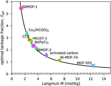 | ||
| Fig. 7 The relationship between the tankage fraction of each optimized adsorbed xenon storage system and the saturation loading of xenon in the adsorbent, M. The solid curve shows the approximation to the optimal tankage fraction in eqn (13). | ||
We use the approximation in eqn (13) to estimate that, for an adsorbed storage system to give a lower optimal tankage fraction than the bulk storage system, the saturation loading of xenon in the adsorbent must exceed 94 mol kg−1, much larger than seen for the adsorbents in Table 2. Based on the relationship between M and ρads in Fig. 5b, such an adsorbent must not be dense. Indeed, lighter adsorbents (lower ρads) also tend to give adsorbed Xe storage systems with lower optimal tankage fractions; see Fig. S2 (ESI†).
We also find that nanoporous materials that exhibit high gravimetric surface areas (defined by the zero potential energy contour of a xenon adsorbate in the pores, computed in iRASPA47,48) tend to provide lower tankage fractions. See Fig. S3 (ESI†). Similarly, virtual screenings of MOFs for hydrogen storage show that MOFs with high gravimetric surface areas tend to have the highest deliverable capacities of hydrogen;49 however, for methane storage, intermediate gravimetric surface areas are desirable.50
5 Limitations
Our mathematical model and the conclusions we extract from it are subject to several limitations emanating from simplifying model assumptions. We discuss some of these below.The safety factor
The choice of the safety factor influences the comparison between adsorbents and between adsorbed and bulk storage systems (see eqn (5) and (12)) because it scales the contribution to the tankage fraction by the metal composing the vessel walls. We crudely investigated the sensitivity of our results to β: only when β < ≈0.05 does the tankage fraction of MOF-505 compete with the bulk storage system. For this very low β, only CC3 and HKUST-1 switch rankings, indicating the ranking of adsorbents here is insensitive to the choice of β.Extrapolation of data on adsorbed xenon density in the nanoporous materials
We used fitted Langmuir adsorption models to extrapolate experimental adsorption data, which is available only up to ca. 1 bar (see Fig. 5a). Though we excluded adsorbents from our study whose adsorption isotherm data did not exhibit a plateau for reliable estimation of the saturation loading M, this extrapolation could still introduce significant error.Bulk vs. crystal density of the nanoporous materials
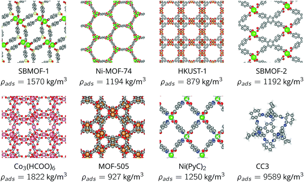
The bulk density of the nanoporous material, ρads, influences the optimum storage pressure and tankage fraction of the adsorbed xenon storage system. See eqn (11) and (12). For each nanoporous material, we approximated ρads as its crystal density (easily computed from its crystal structure, listed in Fig. 4) because bulk densities were not reported for each nanoporous material in our study. However, in practice, the adsorbent when packed into a pressure vessel will take the form of a compacted powder forming granules or pellets; the bulk density of such MOF powders is usually lower than the crystal density owing to interstitial voids.28–31,51We now investigate how our approximation, bulk density of the nanoporous material ρads ≈ crystal density, influences our results. We properly used measured bulk/tap densities reported for CC3, HKUST-1, and Ni-MOF-7428 (see Fig. S4a, ESI†) for ρads in our model to investigate how the tankage fraction changes for these materials, compared to when we used the crystal density. Fig. S4b (ESI†) shows that, for these three materials for which the bulk density was available: when inputting into our model the more realistic bulk density for ρads instead of the crystal density, the optimal storage pressures are reduced, but, the tankage fraction increases only marginally. The latter is consistent with the approximation of the tankage fraction in eqn (13), which does not involve ρads. I.e., the approximation bulk density ≈ crystal density is unlikely to influence our conclusion that the adsorbed storage systems we considered do not provide lower tankage fractions than a bulk storage system.
The paucity of material space sampled
We only considered the eight nanoporous materials in Fig. 4 owing to a paucity of experimentally measured xenon adsorption isotherms for input to our model. Fig. 5b displays the diversity of the material parameters {M,K,ρads} among this set of materials. There are thousands of additional existing MOFs52,53 that could, possibly, provide a lower tankage fraction than the bulk storage system.Thin-wall approximation for the pressure vessel
We invoked the thin-wall approximation to determine the thickness of the walls of the pressure vessel viaeqn (2). Fig. 3 and 6b show that, indeed, r ≫ t, making this approximation reasonable.Geometry of the pressure vessel
We took the pressure vessel to be a sphere. Different pressure vessel geometries will require a different mechanical model to determine the mass of vessel material needed to safely contain the xenon.A pressure vessel composed of a titanium alloy
For a simple estimate, we took the pressure vessel as composed of a titanium alloy. In practice, composite overwrapped pressure vessels (COPVs) are typically used for xenon propellant storage. In a COPV, a gas-impermeable, metallic inner-liner is overwrapped with a strong, permeable carbon fiber overwrap such as Kevlar. The partnership between these materials could allow for a lighter pressure vessel.54,55Residual gas in the adsorbent
A consideration for adsorbed gas storage is the residual gas trapped in the adsorbent at the desorption conditions. Studies on vehicular methane or hydrogen gas storage and delivery via adsorbents use the deliverable capacity of the gas in the material- the density of gas in the material at the storage condition minus the residual gas at the discharge condition56,57- as a performance metric for the material. We assumed the deliverable capacity of xenon in the adsorbent is equal to the adsorbed xenon density at the storage pressure because, in space, the discharge pressure corresponds to vacuum. I.e., we assume that the xenon gas adsorbed in the material at the storage pressure P can be fully delivered.Temperature of 298 K
We assumed a constant storage temperature of 298 K, as in ref. 8 and 25. The performance of adsorbents compared to bulk storage could be improved by lowering the storage temperature, since generally adsorbents will achieve a higher adsorbed xenon density at lower temperatures. However, the insulation and/or refrigeration system required to maintain a lower storage temperature25 would contribute more mass to the storage system and complicate its design.6 Conclusions and future work
We formulated a simple mathematical model of an adsorbed xenon propellant storage system by coupling (i) a stress model for the thin-walled, spherical pressure vessel and (ii) a Langmuir adsorption model to describe the adsorbed xenon density in the porous material. We used the model to find the optimum storage pressure that minimizes the mass of the storage materials (composed of (i) the metal comprising the walls of the pressure vessel and (ii) the adsorbent material) required to carry the xenon onboard the spacecraft. We derived eqn (11) and (12), interpretable expressions for the optimum storage pressure and associated minimum tankage fraction, revealing how properties of the materials (both the metal and the adsorbent) affect the performance of the adsorbed xenon storage system. Fig. 6 compares the performance of several adsorbent materials for Xe propellant storage, with bulk Xe storage as a baseline.We conclude that, for the adsorbent materials considered in Fig. 4, the reduction in the mass of the pressure vessel walls, enabled by reduced storage pressures provided by the adsorbents, does not compensate for the added mass of adsorbent material. That is, an adsorbed Xe storage system does not provide weight savings compared to the bulk Xe storage system. Because the mass of the adsorbent dominates the tankage fraction, the tankage fraction is, to first order approximation, inversely related to the gravimetric saturation loading of xenon in the adsorbent [units: amount of Xe per mass of adsobent]. Our model suggests to, in pursuit of an adsorbent that can outperform the bulk storage system, search for adsorbents that (i) are not dense and (ii) have a very high gravimetric xenon saturation loading, >94 mmol Xe g−1 adsorbent.
Ni-MOF-74 and MOF-505 do, however, offer an improved tankage fraction over the traditional adsorbent, activated carbon, which was previously considered for xenon propellant storage.10
N.B., the optimal storage pressure and tankage fraction of an adsorbed Xe propellant storage system depend on the xenon adsorption isotherm in the adsorbent, the density of the adsorbent, and the properties (density, yield strength) of the material composing the walls of the pressure vessel.
Our model is only a first-order approximation/Fermi estimate to approach the question of whether nanoporous materials are a worthy pursuit for xenon propellant storage, with the objective of minimizing the mass of the storage materials. We listed and discussed several limitations of our model above.
Future work includes (a) developing a COPV stress model and coupling it with the adsorbent model, (b) considering different tank geometries, and (c) expanding the scope of adsorbent materials considered by e.g., a high-throughout computational screening of materials for xenon propellant storage.58–60
Conflicts of interest
There are no conflicts of interest to declare.Acknowledgements
N. G., P. K. T., and C. M. S. acknowledge the U.S. Department of Defense (DoD) Defense Threat Reduction Agency (HDTRA-19-31270) for the necessary funding and support. PNNL is operated by Battelle for the U.S. DOE under contract DE-AC05-76RL01830. We thank our DTRA program manager Dr Calvin L. Shipbaugh for support. M. T. H. and S. H. thank the Pete and Rosalie Johnson Internship Program at Oregon State University.References
- J. S. Sovey, V. K. Rawlin and M. J. Patterson, Ion propulsion development projects in US: Space Electric Rocket Test I to Deep Space 1, J. Propul. Power, 2001, 17(3), 517–526 CrossRef CAS.
- J. R. Brophy, NASA's Deep Space 1 ion engine (plenary), Rev. Sci. Instrum., 2002, 73(2), 1071–1078 CrossRef CAS.
- V. Rawlin, M. Patterson and R. Gruber, Xenon ion propulsion for orbit transfer, in 21st International Electric Propulsion Conference, page 2527, 1990.
- J. R. Beattie, J. N. Matossian and R. Robson, Status of xenon ion propulsion technology, J. Propul. Power, 1990, 6(2), 145–150 CrossRef CAS.
- W. Tam, A. Jackson, E. Nishida, Y. Kasai, A. Tsujihata and K. Kajiwara, Design and manufacture of the ets viii xenon tank, in 36th American Institute of Aeronautics and Astronautics/American Society of Mechanical Engineers/Society of Automotive Engineers/American Society for Engineering Education Joint Propulsion Conference & Exhibit, page 3677, 2000.
- J. R. Beattie, J. N. Matossian, R. L. Poeschel, W. P. Rogers and R. M. Martinelli, Xenon ion propulsion subsystem, J. Propul. Power, 1989, 5(4), 438–444 CrossRef CAS.
- J. Brophy, M. Marcucci, J. Gates, C. Garner, B. Nakazono and G. Ganapathi, Status of the DAWN ion propulsion system, in 40th AIAA/ASME/SAE/ASEE Joint Propulsion Conference and Exhibit, page 3433, 2004.
- J. R. Brophy, R. Y. Kakuda, J. E. Polk, J. R. Anderson, M. G. Marcucci, D. Brinza, M. D. Henry, K. K. Fujii, K. R. Mantha, J. F. Stocky, J. Sovey, M. Patterson, V. Rawlin, J. Hamley, T. Bond, J. Christensen, H. Cardwell, G. Benson, J. Gallagher, M. Matranga and D. Bushway, Ion propulsion system (NSTAR) DS1 technology validation report, Deep Space 1 Technology Validation Report-Ion Propulsion System (NSTAR), 2000.
- B. Dunbar, Advanced space transportation program fact sheet, National Aeronautics and Space Administration - Marshall Space Flight Center Archives, 12, 2008.
- D. D. Back, C. Ramos and J. A. Meyer. Low-pressure long-term xenon storage for electric propulsion, NASA, 2001.
- H. Furukawa, K. E. Cordova, M. O’Keeffe and O. M. Yaghi, The chemistry and applications of metal-organic frameworks, Science, 2013, 341(6149), 1230444 CrossRef PubMed.
- A. I. Cooper, Porous molecular solids and liquids, ACS Cent. Sci., 2017, 3(6), 544–553 CrossRef CAS PubMed.
- C. S. Diercks and O. M. Yaghi, The atom, the molecule, and the covalent organic framework, Science, 2017, 355(6328), eaal1585 CrossRef PubMed.
- O. K. Farha, I. Eryazici, N. Cheon Jeong, B. G. Hauser, C. E. Wilmer, A. A. Sarjeant, R. Q. Snurr, S. B. T. Nguyen, A. “Ozg”ur Yazaydn and J. T. Hupp, Metal-organic framework materials with ultrahigh surface areas: is the sky the limit?, J. Am. Chem. Soc., 2012, 134(36), 15016–15021 CrossRef CAS PubMed.
- Y. Song, Q. Sun, B. Aguila and S. Ma, Opportunities of covalent organic frameworks for advanced applications, Adv. Sci., 2019, 6(2), 1801410 CrossRef PubMed.
- A. Schoedel, Z. Ji and O. M. Yaghi, The role of metal-organic frameworks in a carbon-neutral energy cycle, Nat. Energy, 2016, 1(4), 1–13 Search PubMed.
- D. Banerjee, C. M. Simon, A. M. Plonka, R. K. Motkuri, J. Liu, X. Chen, B. Smit, J. B. Parise, M. Haranczyk and P. K. Thallapally, Metal-organic framework with optimally selective xenon adsorption and separation, Nat. Commun., 2016, 7(1), 1–7 Search PubMed.
- D. Banerjee, C. M. Simon, S. K. Elsaidi, M. Haranczyk and P. K. Thallapally, Xenon gas separation and storage using metal-organic frameworks, Chem, 2018, 4(3), 466–494 CAS.
- D. Banerjee, A. J. Cairns, J. Liu, R. K. Motkuri, S. K. Nune, C. A. Fernandez, R. Krishna, D. M. Strachan and P. K. Thallapally, Potential of metal-organic frameworks for separation of xenon and krypton, Acc. Chem. Res., 2015, 48(2), 211–219 CrossRef CAS PubMed.
- S. K. Elsaidi, D. Ongari, M. H. Mohamed, W. Xu, R. Kishan Motkuri, M. Haranczyk and P. K. Thallapally, Metal organic frameworks for xenon storage applications, ACS Mater. Lett., 2020, 2(3), 233–238 CrossRef CAS.
- C. T. Herakovich. Thin-walled pressure vessels, A Concise Introduction to Elastic Solids, Springer, 2017, pp. 77–81 Search PubMed.
- G. Welsch, R. Boyer and E. W. Collings, Materials properties handbook: titanium alloys, American Society for Metals International, 1993 Search PubMed.
- M. Niinomi, Mechanical properties of biomedical titanium alloys, Mater. Sci. Eng., A, 1998, 243(1–2), 231–236 CrossRef.
- C. W. Bert, E. J. Mills and W. S. Hyler. Mechanical properties of aerospace structural alloys under biaxial-stress conditions. Technical Report TR-66-229, Battelle Memorial Institute - Columbus Laboratories, Air Force Materials Laboratory, Wright-Patterson AFB, Ohio, 1966.
- R. P. Welle, Propellant storage considerations for electric propulsion, in 22nd International Electric Propulsion Conference, pages 91–107, 1991.
- M. O. McLinden, E. W. Lemmon and D. G. Friend, Thermophysical Properties of Fluid Systems” in NIST Chemistry WebBook, NIST Standard Reference Database Number 69, ed. P. J. Linstrom and W.G. Mallard, National Institute of Standards and Technology, Gaithersburg MD, 20899, retrieved February 5, 2020 DOI:10.18434/T4D303.
- H. Swenson and N. P. Stadie, Langmuir's theory of adsorption: A centennial review, Langmuir, 2019, 35(16), 5409–5426 CrossRef CAS PubMed.
- K. J. Korman, G. E. Decker, M. R. Dworzak, M. M. Deegan, A. M. Antonio, G. A. Taggart and E. D. Bloch., Using low-pressure methane adsorption isotherms for higher-throughput screening of methane storage materials, ACS Appl. Mater. Interfaces, 2020, 12(36), 40318–40327 CrossRef CAS PubMed.
- B. Valizadeh, T. N. Nguyen and K. C. Stylianou., Shape engineering of metal-organic frameworks, Polyhedron, 2018, 145, 1–15 CrossRef CAS.
- M. Kunowsky, F. Suárez-Garca and Á. Linares-Solano, Adsorbent density impact on gas storage capacities, Microporous Mesoporous Mater., 2013, 173, 47–52 CrossRef CAS.
- J. Dhainaut, C. Avci-Camur, J. Troyano, A. Legrand, J. Canivet, I. Imaz, D. Maspoch, H. Reinsch and D. Farrusseng, Systematic study of the impact of MOF densification into tablets on textural and mechanical properties, CrystEngComm, 2017, 19(29), 4211–4218 RSC.
- D. Banerjee, Z. Zhang, A. M. Plonka, J. Li and J. B. Parise., A calcium coordination framework having permanent porosity and high CO2/N2 selectivity, Cryst. Growth Des., 2012, 12(5), 2162–2165 CrossRef CAS.
- N. L. Rosi, J. Kim, M. Eddaoudi, B. Chen, M. O'Keeffe and O. M. Yaghi, Rod packings and metal-organic frameworks constructed from rod-shaped secondary building units, J. Am. Chem. Soc., 2005, 127(5), 1504–1518 CrossRef CAS PubMed.
- S. S.-Y. Chui, S. M.-F. Lo, J. P. H. Charmant, A. G. Orpen and I. D. Williams., A chemically functionalizable nanoporous material [Cu3(TMA)2(H2O)3]n, Science, 1999, 283(5405), 1148–1150 CrossRef CAS PubMed.
- X. Chen, A. M. Plonka, D. Banerjee, R. Krishna, H. T. Schaef, S. Ghose, P. K. Thallapally and J. B. Parise, Direct observation of Xe and Kr adsorption in a Xe-selective microporous metal-organic framework, J. Am. Chem. Soc., 2015, 137(22), 7007–7010 CrossRef CAS.
- K. Li, D. H. Olson, J. Y. Lee, W. Bi, K. Wu, T. Yuen, Q. Xu and J. Li, Multifunctional Microporous MOFs Exhibiting Gas/Hydrocarbon Adsorption Selectivity, Separation Capability and Three-Dimensional Magnetic Ordering, Adv. Funct. Mater., 2008, 18(15), 2205–2214 CrossRef CAS.
- B. Chen, N. W. Ockwig, A. R. Millward, D. S. Contreras and O. M. Yaghi, High H2 adsorption in a microporous metal-organic framework with open metal sites, Angew. Chem., Int. Ed., 2005, 44(30), 4745–4749 CrossRef CAS PubMed.
- X. Lin, I. Telepeni, A. J. Blake, A. Dailly, C. M. Brown, J. M. Simmons, M. Zoppi, G. S. Walker, K. M. Thomas, T. J. Mays, P. Hubberstey, N. R. Champness and M. Schroder, High capacity hydrogen adsorption in Cu (II) tetracarboxylate framework materials: the role of pore size, ligand functionalization, and exposed metal sites, J. Am. Chem. Soc., 2009, 131(6), 2159–2171 CrossRef CAS PubMed.
- D. Chakraborty, S. Nandi, R. Maity, R. K. Motkuri, K. S. Han, S. Collins, P. Humble, J. C. Hayes, T. K. Woo, R. Vaidhyanathan and P. K. Thallapally, An ultra-microporous metal–organic framework with exceptional xe capacity, Chem. – Eur. J., 2020, 26(55), 12544–12548 CrossRef CAS PubMed.
- T. Tozawa, J. T. A. Jones, S. I. Swamy, S. Jiang, D. J. Adams, S. Shakespeare, R. Clowes, D. Bradshaw, T. Hasell, S. Y. Chong, C. Tang, S. Thompson, J. Parker, A. Trewin, J. Bacsa, A. M. Z. Slawin, A. Steiner and A. I. Cooper, Porous organic cages, Nat. Mater., 2009, 8(12), 973–978 CrossRef CAS PubMed.
- H. Wang, K. Yao, Z. Zhang, J. Jagiello, Q. Gong, Y. Han and J. Li, The first example of commensurate adsorption of atomic gas in a mof and effective separation of xenon from other noble gases, Chem. Sci., 2014, 5(2), 620–624 RSC.
- J. J. Perry IV, S. L. Teich-McGoldrick, S. T. Meek, J. A. Greathouse, M. Haranczyk and M. D. Allendorf, Noble gas adsorption in metal-organic frameworks containing open metal sites, J. Phys. Chem. C, 2014, 118(22), 11685–11698 CrossRef.
- L. Chen, P. S. Reiss, S. Y. Chong, D. Holden, K. E. Jelfs, T. Hasell, M. A. Little, A. Kewley, M. E. Briggs, A. Stephenson, K. M. Thomas, J. A. Armstrong, J. Bell, J. Busto, R. Noel, J. Liu, D. M. Strachan, P. K. Thallapally and A. I. Cooper, Separation of rare gases and chiral molecules by selective binding in porous organic cages, Nature Materials, 2014, 13(10), 954–960 CrossRef CAS PubMed.
- P. K. Thallapally, J. W. Grate and R. K. Motkuri, Facile xenon capture and release at room temperature using a metal-organic framework: a comparison with activated charcoal, Chem. Commun., 2012, 48(3), 347–349 RSC.
- AquaCarb and Westates. Westates® coconut shell based granular activated carbon - aquacarb® 830c, 1230c and 1240c carbons. https://www.evoqua.com/siteassets/documents/products/carbon-resin/wsaq12ds.pdf, 2017.
- S. T. Meek, S. L. Teich-McGoldrick, J. J. Perry, J. A. Greathouse and M. D. Allendorf, Effects of polarizability on the adsorption of noble gases at low pressures in monohalogenated isoreticular metal-organic frameworks, J. Phys. Chem. C, 2012, 116(37), 19765–19772 CrossRef CAS.
- D. Dubbeldam, S. Calero, D. E. Ellis and R. Q. Snurr, RASPA: molecular simulation software for adsorption and diffusion in flexible nanoporous materials, Mol. Simul., 2015, 42(2), 81–101 CrossRef.
- D. Dubbeldam, S. Calero and T. J. H. Vlugt, iRASPA: GPU-accelerated visualization software for materials scientists, Mol. Simul., 2018, 44(8), 653–676 CrossRef CAS.
- A. Ahmed, S. Seth, J. Purewal, A. G. Wong-Foy, M. Veenstra, A. J. Matzger and D. J. Siegel, Exceptional hydrogen storage achieved by screening nearly half a million metal-organic frameworks, Nat. Commun., 2019, 10(1), 1568 CrossRef PubMed.
- C. E. Wilmer, M. Leaf, C. Yeon Lee, O. K. Farha, B. G. Hauser, J. T. Hupp and R. Q. Snurr, Large-scale screening of hypothetical metal–organic frameworks, Nat. Chem., 2011, 4(2), 83–89 CrossRef PubMed.
- C. D. Wood, B. Tan, A. Trewin, F. Su, M. J. Rosseinsky, D. Bradshaw, Y. Sun, L. Zhou and A. I. Cooper, Microporous organic polymers for methane storage, Adv. Mater., 2008, 20(10), 1916–1921 CrossRef CAS.
- P. Z. Moghadam, A. Li, S. B. Wiggin, A. Tao, A. G. P. Maloney, P. A. Wood, S. C. Ward and D. Fairen-Jimenez, Development of a cambridge structural database subset: a collection of metal–organic frameworks for past, present, and future, Chem. Mater., 2017, 29(7), 2618–2625 CrossRef CAS.
- Y. G. Chung, E. Haldoupis, B. J. Bucior, M. Haranczyk, S. Lee, H. Zhang, K. D. Vogiatzis, M. Milisavljevic, S. Ling, J. S. Camp, B. Slater, J. I. Siepmann, D. S. Sholl and R. Q. Snurr., Advances, updates, and analytics for the computation-ready, experimental metal–organic framework database: CoRE MOF 2019, J. Chem. Eng. Data, 2019, 64(12), 5985–5998 CrossRef CAS.
- M. Kezirian, K. Johnson and S. Phoenix, Composite overwrapped pressure vessels (COPV): Flight rationale for the Space Shuttle Program, In American Institute of Aeronautics and Astronautics Space 2011 Conference & Exposition, page 7363, 2011.
- W. Radtke, Manufacturing of advanced titanium (lined) propellant tanks and high pressure vessels. Proceedings of the 4th International Spacecraft Propulsion Conference (ESA SP-555), 2004.
- P. García-Holley, B. Schweitzer, T. Islamoglu, Y. Liu, L. Lin, S. Rodriguez, M. H. Weston, J. T. Hupp, D. A. Gómez-Gualdrón, T. Yildirim and O. K. Farha, Benchmark study of hydrogen storage in metal–organic frameworks under temperature and pressure swing conditions, ACS Energy Lett., 2018, 3(3), 748–754 CrossRef.
- J. A. Mason, M. Veenstra and J. R. Long, Evaluating metal-organic frameworks for natural gas storage, Chem. Sci., 2014, 5(1), 32–51 RSC.
- A. Sturluson, M. T. Huynh, A. R. Kaija, C. Laird, S. Yoon, F. Hou, Z. Feng, C. E. Wilmer, Y. J. Colón, Y. G. Chung, D. Siderius and C. Simon, The role of molecular modelling and simulation in the discovery and deployment of metal-organic frameworks for gas storage and separation, Mol. Simul., 2019, 45(14–15), 1082–1121 CrossRef CAS PubMed.
- H. Daglar and S. Keskin, Recent advances, opportunities, and challenges in high-throughput computational screening of MOFs for gas separations, Coord. Chem. Rev., 2020, 422, 213470 CrossRef CAS.
- P. G. Boyd, Y. Lee and B. Smit, Computational development of the nanoporous materials genome, Nat. Rev. Mater., 2017, 2(8), 17037 CrossRef CAS.
Footnotes |
| † Electronic supplementary information (ESI) available. See DOI: 10.1039/d1ma00167a |
| ‡ Recall, under the thin-walled vessel approximation, we do not distinguish between an outer- and inner-volume. |
| This journal is © The Royal Society of Chemistry 2021 |

