 Open Access Article
MnO2/MXene–Ti3C2Tx flexible foam for use in lithium ion storage†
Jingze
Yan
a,
Lu
Yu
a,
Donghua
Wang
a,
Wenyuan
Zhang
a,
Zhihao
Xiong
a,
Tianshuo
Nie
a,
Zhen
Ji
*a and
Xiaoqin
Yan
 *ab
*ab
aState Key Laboratory for Advanced Metals and Materials, School of Materials Science and Engineering, University of Science and Technology Beijing, Beijing, 100083, P. R. China. E-mail: xqyan@mater.ustb.edu.cn; jizhen@mater.ustb.edu.cn
bThe Beijing Municipal Key Laboratory of New Energy Materials and Technologies, University of Science and Technology Beijing, Beijing, 100083, P. R. China
First published on 5th June 2021
Abstract
As a new two-dimensional material, MXene has attracted extensive attention because of its unique structure and electrochemical properties. MXene-based self-supporting films have been widely studied due to their flexibility, light weight and lack of need for adhesives and conductive agents. In the present work, we used facile ultrasonic and annealing methods to fabricate MnO2/MXene–Ti3C2Tx foam hybrids for lithium storage. In the hybrid material, MnO2 nanoparticles expand the MXene lamellar spacing, provide tunnels for lithium ion shuttling and accelerate the transport speed of lithium ions, thus improving the rate performance of the electrode materials. The existence of the MXene nanosheets can release the internal stress due to the volume expansion of MnO2 during charging/discharging, reduce the electrode resistivity and improve the cycling stability of materials. The initial discharge capacity can reach 1203 mA h g−1 and the capacity can be maintained at about 600 mA h g−1 after 200 cycles. Moreover, the capacity of the electrode attenuates less at a large current and the capacity is about 350 mA h g−1 at 5 A g−1.
1. Introduction
The world’s energy crisis has promoted the rapid development of new energies such as wind and solar energy, but their fatal problem is that they are intermittent.1–3 This results in higher requirements for energy storage. The Li–ion batteries used at present have high energy density but lower power density.4,5 Although supercapacitors (SCs) have outstanding specific power, their energy density is insufficient. Therefore, the development of power storage components with excellent specific power and energy density is required.6,7 As a result, researchers have begun to exploit new electrodes with excellent specific capacities and the high-speed transmission of lithium ions.8Transition metal oxides (TMO) are widely used in Li–ion storage because of their high theoretical lithium storage capacity.9–11 MnO2 has received extensive attention due to its low cost and excellent lithium storage capacity (1230 mA h g−1).12 Nevertheless, the low conductivity and poor Li–ion diffusion kinetics greatly restrict its charge/discharge rate. In addition, the large volume changes of MnO2 during continuous Li+ intercalation/deintercalation will lead to poor cycling performance and a short electrode life. In response to these problems, developing TMO-based composite electrode materials has become a main research direction.13–16
Two-dimensional materials have received widespread attention because of their large specific surface areas and short ion transmission paths, and they also have great potential for development in the domain of energy.17 The thickness of 2D materials is at the level of only one atom, so they have many surface active sites and excellent mechanical properties. 2D materials are in line with the requirements of energy storage devices for electrode materials.18,19 As a new 2D material, MXene has been widely used in energy storage devices, for instance Li-ion batteries, Li–S batteries and SCs.20–22 Because of the unique structure of MXene, such as the conductive layer of carbon and abundant surface functional groups, it has an unexpected electrochemical performance.
MXene-based self-supporting films have been widely studied due to their flexibility, light weight and lack of need for adhesives and conductive agents.23 However, similarly to graphene, single-layer or few-layer MXene will form strong van der Waals bonds between the layers during the film formation process by suction, which leads to the aggregation of MXene sheets.24 The tight self-agglomerating structure decreases the active sites on the surface of electrode, attenuates the lithium ion transport dynamics and makes it difficult for lithium ions to reach the inside of the electrode.25,26 There are two main methods to improve the kinetics of Li-ion diffusion in MXene self-supporting films. One is to introduce various nanomaterial spacers such as transition metal oxides to prepare composite electrodes; the other is to modify MXene films such as by preparing MXene foams.
Effective electrode structure design strategies can increase the active sites on the surface of electrode, widen the lithium ion transmission channels, shorten the Li–ion transmission paths and decrease the electronic resistivity of the electrode. TMO/MXene hybrid structure electrodes have a higher specific capacity due to the presence of TMO and the presence of MXene can release the internal stress generated by the deformation in the charging/discharging process of TMO, so that the electrode has good cycling performance.27 The preparation of MXene foam can expand the interlayer spacing and provide a lot of space inside the electrode. On the one hand, these spaces can be used as a buffer layer for lithium storage, and on the other hand, they can provide a fast path for lithium ion diffusion and shorten the lithium ion transmission path.28,29
In this work, we combined these two methods to design a MnO2/MXene foam composite structure electrode. The structural advantages of the MnO2/MXene foam electrode are: (i) the introduction of MnO2 greatly improves the specific capacity of the electrode, (ii) MnO2 inserts into MXene layers and effectively inhibits the stacking and agglomeration of MXene, (iii) MXene foam can provide space for MnO2 and release the stress caused by its volume change, (iv) MXene foam shortens the lithium ion transmission path and widens the lithium ion transmission channel and (v) MXene has outstanding electronic conductivity (over 8000 S cm−1) and can reduce the electrode resistance. As a result, the MnO2/MXene foam composite structure possesses a variety of valuable attributes. It shows outstanding deformability (it bends, twists and even folds) and it also has excellent mechanical properties. We assembled a half-cell using the MnO2/MXene foam as the positive electrode and a Li sheet as the negative electrode. Then, we tested its electrochemical performance using a variety of test methods and it showed excellent electrochemical performance and cycle stability.30
2. Materials and characterization
Synthesis of the MnO2 nano-particles
We used a simple neutralization reaction to prepare the manganese dioxide nanoparticles. 63 mg MnCl2 was dispersed in 30 ml H2O under vigorous magnetic stirring. A potassium permanganate solution was prepared with a concentration of 7.9 g L−1. 10 ml of the solution was taken and poured into the heated MnCl2 solution. The resulting solution was heated to 100 °C and kept for 6 hours. After six hours of magnetic stirring, it was washed by centrifugation. The cleaned MnO2 was put into a blast drying box for drying and was ground after drying.31Synthesis of few-layered Ti3C2Tx
Few-layered Ti3C2Tx was prepared by etching Ti3AlC2. 1 g LiF (99%) was added to 20 ml HCl solution (9 M), then 1 g Ti3AlC2 was added to the mixture solution slowly. The solution was stirred for 24 hours at 35 °C. Then, it was washed with deionized water by centrifugation until the pH value of the supernatant was higher than 5. Multi-layered Ti3C2Tx was obtained by collecting the precipitate. Multi-layered Ti3C2Tx was dispersed in 150 ml of deionized water and sonicated in an Ar atmosphere for an hour. Finally, the dispersion liquid was centrifuged at 4000 rpm for 30 minutes, and the supernatant, which was the few-layered Ti3C2Tx MXene suspension, was collected.32,33Synthesis of the MXene film
The content of delaminated MXene in the suspension was measured by vacuum filtering and drying the MXene–Ti3C2Tx suspension. The MXene–Ti3C2Tx suspension (20 ml) was taken, 20 ml of deionized water was added to it and then it was sonicated for 30 minutes in an Ar atmosphere. The MXene film was obtained by vacuum filtering the MXene suspension on a PES (polyethersulfone resin) filter membrane. Finally, it was annealed for two hours in an argon atmosphere at 120 °C.34Synthesis of the MnO2/MXene foam
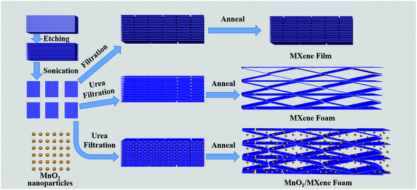
MXene–Ti3C2Tx suspension (20 ml) was taken, 20 ml of deionized water was added to it, and then it was sonicated for 30 minutes in an Ar atmosphere. MnO2 nanoparticles (10 mg) and urea (100 mg) were added to the MXene suspension, then sonicated for 10 minutes in an Ar atmosphere. The MnO2/MXene film was obtained by the vacuum filtration of the MnO2@MXene suspension on a PES filter membrane. The MnO2/MXene film was put into a tube furnace and heated to 400 °C (5 °C min−1) under Ar flow for 3 hours. In the end, the MnO2/MXene foam with a structure with plentiful pores was achieved.Characterization
Scanning electron microscopy (SEM) (SU8220, Hitachi Ltd), transmission electron microscopy (TEM) (G2F20U-TWIN, FEI) and atomic force microscopy (AFM) (NT-MDT Prima, Bruker Dimension Edge) were used for observing the surface morphology of the electrode. Scanning electron microscopy (SEM) was used for element mapping analysis and energy spectrum analysis (EDS). The X-ray diffraction (XRD) instrument (D/MAX-TTRIII(CBO)) was used to measure the crystallinity of the materials. The X-ray photoelectron spectroscopy (XPS) of the material was performed with a photoelectron spectrometer (ESCALAB250Xi).Electrochemical measurements
Electrochemical measurements were carried out by assembling a half-cell with the MnO2/MXene foam as the positive electrode and a Li sheet as the negative electrode. The positive electrode was prepared by cutting the MXene self-supporting film or MnO2/MXene foam into sections with a diameter of 12 mm. The negative electrode was pure Li foil. The process of assembling the half-cell was carried out in a glove box with an Ar atmosphere.35 Cyclic voltammogram (CV) experiments from 0.01–3 V and electrochemical impedance spectra (EIS) in the frequency range of 100 kHz–0.01 Hz were performed on a CHI660 electrochemical workstation. Galvanostatic charge/discharge tests, cycling performance and rate of dischargeability were performed on a CT-4000 batteries tester (NEWARE Instruments Inc.) at different current densities.3. Results and discussion
The preparation method of the MnO2/MXene foam is shown in Fig. 1; the MnO2 nanoparticles and the MXene suspension were mixed uniformly and vacuum filtered to obtain the MnO2/MXene film, and then annealed to obtain the MnO2/MXene foam. The MXene–Ti3C2Tx nanosheet suspension was obtained by selectively etching the aluminum atoms of Ti3AlC2, centrifugal cleaning and ultrasonic dispersion. In such hybrids, the few-layered Ti3C2Tx nanosheets are reckoned to relieve the stress generated by the volume expansion of MnO2 nanoparticles during the charge/discharge process, so they can maintain great structural integrity. The presence of MnO2 nanoparticles can prevent MXene stacking. During the annealing process, urea decomposes at a high temperature to generate gas, which will create a lot of space in the MXene film to form a foam structure.36Fig. 2 shows macro photographs of the MXene film prepared by suction filtration and the three electrodes. Fig. 2(a and b) show that the MXene film has a defined shape and good flexibility. The MXene foam has poor flexibility. It can be seen that there are obvious bubbles on the surface of the MXene foam compared with the MXene film electrode. However, the bubbles are large and unevenly distributed, which may be caused by uneven foaming caused by the accumulation of urea during the suction filtration process. The surface of the MnO2/MXene foam electrode also has bubbles and the distribution of the bubbles is relatively uniform. The MXene film electrode, MXene foam electrode and MnO2/MXene foam electrode weights are 1.8–1.9 mg, 1.8–1.9 mg and 1.9–2.0 mg respectively. The MnO2/MXene foam also has good flexibility, but compared with that of the MXene film this is relatively poor (Fig. S1, ESI†).
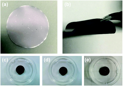 | ||
| Fig. 2 Picture of (a) and (b) the MXene film, (c) the MXene film electrode, (d) the MXene foam electrode and (e) the MnO2/MXene foam electrode. | ||
Compared with ordinary film, the foam structure has many advantages. It can provide more expansion space for active materials and can effectively shorten the lithium ion transmission distance, thereby achieving high-speed lithium ion storage. At the same time, the MnO2/MXene foam is a self-supporting structure without the need to add conductive agents and binders. It has good structural stability and is conducive to high-speed lithium ion storage.
Fig. 3(a–d) show the SEM images of the MXene film, MXene foam and MnO2/MXene foam. In Fig. 3(a), the MXene film has a book-like structure and the MXene nanosheets are closely packed together with small interlayer spacing. This structure makes it difficult for the inside of the electrode to contact the electrolyte and inhibits the rapid transmission of lithium ions. Moreover, this structure cannot release the internal stress generated by the insertion of Li ions between the layers. Fig. 3(b) shows the SEM image of the MXene foam formed after annealing with urea. The gaps between the electrode layers become larger, with the electrode showing a foam-like structure with abundant voids. This is because the urea between the MXene sheets is thermally decomposed to generate gas during the annealing process and the gas expansion causes the gaps between the electrode sheets to expand. Compared with the book-like structure of the MXene film, the electrode structure has large interlayer spacing, which is beneficial for the fast transmission of lithium ions.
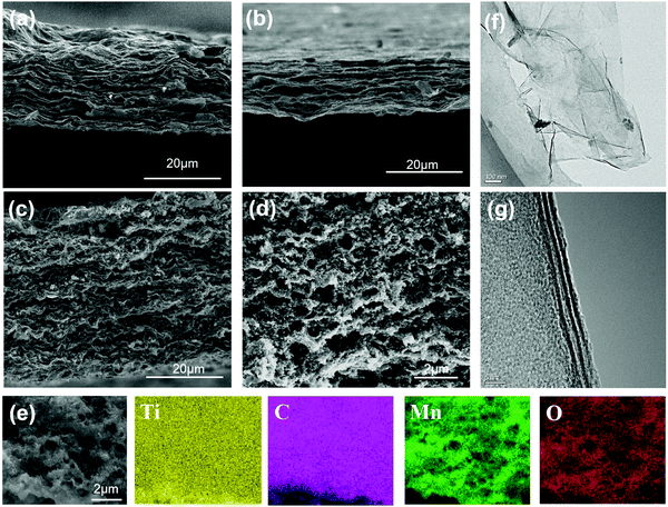 | ||
| Fig. 3 SEM images of (a) the MXene film, (b) the MXene foam, (c and d) the MnO2/MXene foam; (e) EDS mapping images of the MnO2/MXene foam (Ti, C, Mn and O) by SEM and (f and g) TEM of MXene–Ti3C2Tx. | ||
The SEM image of the MnO2 nanoparticles is shown in Fig. S4 (ESI†). The sizes of the MnO2 nanoparticles are uniform, with a diameter of about 100 nm. The SEM images of the MnO2/MXene electrode are shown in Fig. 3(c and d). Fig. 3(c) shows the MnO2/MXene electrode before annealing. The thickness of the electrode is about 40 microns and the MXene sheets are stacked closely together. The MnO2 nanoparticles are evenly distributed in the MXene layers. Fig. 3(d) shows the structural characteristics of the MnO2/MXene foam. The MnO2 nanoparticles modify the 3D porous MXene self-supporting foam. Through the combined action of the manganese dioxide nanoparticles and the urea foaming treatment, the interlaminar spacing is significantly increased and they are evenly distributed on the foam skeleton. Then, EDS component analysis was performed on the electrode. Fig. 3(e) shows the element distribution maps. The main elements in the electrode are Ti, C, O and Mn. Ti and C are evenly distributed over the entire electrode, and Mn and O are uniformly distributed on the electrode framework. This hybrid is conducive to the rapid diffusion of lithium ions and the abundant internal spaces can effectively release the internal stress generated by the volume change of the MnO2 nanoparticles during Li ion intercalation and de-intercalation. In order to analyze the pore structure of the electrode, BET testing was performed (Fig. S4, ESI†). The specific surface areas of the MXene foam and MnO2/MXene foam are 35.1399 m2 g−1 and 48.4524 m2 g−1 respectively. The smaller specific surface area is due to the larger pore size in the MXene foam, most of which are over 300 nm.
Fig. 3(f and g) show the TEM images of the few-layered MXene–Ti3C2Tx, revealing the wrinkled two-dimensional material characteristics of the few-layer Ti3C2 nanosheets. The size is in the range of 1.0–2.0 μm. Since the two-dimensional material is unstable, surface energy can be released through surface wrinkles and the stability of the material can be improved. As shown in Fig. 3(f), the HR-TEM image shows three dark stripes in the section of MXene, which indicates that the MXene is composed of three layers of Ti3C2. The thickness of MXene is about 4 nanometers. In order to accurately measure its thickness, we use AFM to test MXene. In Fig. S2 (ESI†), the size of the MXene nanosheets is shown to be about 2 μm. The thickness of the MXene nanosheets is about 3.6 nm, which is same as the thickness from the transmission electron microscope, indicating that the number of layers in the MXene suspension is uniform. The MXene nanosheets are thicker at the edges, which is because there are more defects at the edges and Ti atoms are easily oxidized into TiO2.
In order to view the etching of the titanium aluminum carbide, XRD was used to characterize Ti3AlC2 and the MXene–Ti3C2Tx material generated after etching. Fig. 4(a) shows the measured XRD pattern, where the scanning range is 5–90° and the scanning speed is 10° min−1. The Ti3AlC2 crystal belongs to the hexagonal system with the P63/mmc space group, and the lattice parameters are a = 0.30753 nm and c = 1.8575 nm. Six Ti atoms and one C atom form a closely packed common edge Ti6C octahedron. The C atom is located in the center of the octahedral gap and is connected by a plane layer of Al atoms. Each unit cell contains two Ti3AlC2 molecules. The bond between the Ti atoms and C atoms is a strong covalent bond, which gives the material a high melting point and high elastic modulus, while the Ti atoms and Al atoms form a layered structure between the planes, which is formed by weak bonds, similar to the van der Waals forces between graphite layers The weak bond combination makes the Al layer easy to selectively etch. We can see that the characteristic peaks of the crystal planes except that of (002) basically disappear after etching, which demonstrates that the aluminum atoms are selectively etched away, which results in the disappearance of the diffraction peaks of the crystal plane perpendicular to the (002) crystal plane. After the etching is completed, the relative intensity of the characteristic peak of the (002) crystal plane increases, indicating that the prepared MXene material is of good quality; after the etching is completed, the peak of the (002) crystal plane shifts to the left, indicating that the layer spacing is enlarged. Fig. S5 (ESI†) shows the XRD pattern of the MnO2 nanoparticles and MnO2/MXene foam. It can be seen that the MnO2 nanoparticles are β-MnO2 and remain β-MnO2 after annealing.
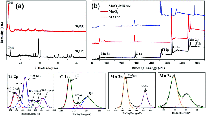 | ||
| Fig. 4 (a) XRD patterns of MXene–Ti3C2Tx and Ti3C2Al; (b) survey scan XPS of MXene, the MnO2 nanoparticles and the MnO2/MXene foam; HR XPS of Ti 2p, C 1s, Mn 2p and Mn 3s of MnO2/MXene. | ||
XPS was used to analyze the composition and chemical valences of the hybrid electrode. MnO2/MXene was mainly made up of Ti, C, Mn, O and F. The HR XPS spectra of the hybrid electrode is shown in Fig. 4(b). The Ti 2p peak of the hybrid electrode can be divided into six individual peaks: Ti–C (2p3/2) at 455.6 eV, Ti–OH at 456.9 eV, Ti–O (2p3/2) at 458.9 eV, Ti–C (2p1/2) at 460.5 eV, Ti–F at 462.1 eV and Ti–O (2p1/2) at 464.7 eV. The C 1s peak can be divided into three individual peaks: C–Ti at 281.2 eV, C–Ti–O at 282.6 eV and C–C at 284.1 eV. These prove that the aluminum in the MAX phase is etched away and forms –F and –O functional groups, which are adsorbed on the surface titanium atoms. Fig. 3(d and e) are Mn 2p and Mn 3s in the MnO2/MXene high-resolution XPS, respectively. The Mn 2p peak can be fitted to two constituent peaks: Mn 2p3/2 at 641.6 eV and Mn 2p1/2 at 653.1 eV. Mn 3s forms double peaks due to its unique photoelectric properties and the difference between the binding energy of the two peaks is 4.7 eV. This shows that the Mn element of the composite electrode is tetravalent.
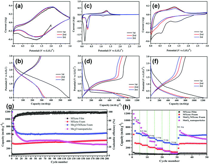
A variety of electrochemical testing methods were used to analyse the electrochemical performance of electrode. Fig. 5(a) displays the CV curve of the MXene foam electrode in the scanning range of 0.01–3 V at a speed of 0.1 mV s−1; the discharge current density in the first cycle is comparatively high, which is because of the formation of the SEI by consuming lithium ions on the electrode surface. The second cycle and the third cycle basically overlap, indicating that the SEI formed in the previous cycle is stable without being broken, and the electrode cycling performance is good. The curve has only two broad characteristic peaks of 1.5 V and 2.0 V, indicating the pseudocapacitive mechanism and non-diffusion limitation of the lithium storage behavior. The cyclic CV curves of the MnO2 nanoparticles are shown in Fig. 5(c). A two-step reaction occurred during the first discharge. First, MnO2 was converted to Mn3O4 at 1.1 V, and then Mn3O4 was converted to Mn at 0.1 V. The following reaction occurred at 1.25 V during charging:
| 2Mn + 4Li2O → 2LiMnO2 + 6Li |
Following this initial lithiation, a two-step conversion reaction could take place. First, Mn2O3 is formed, which acts as an intermediate phase, and then Mn2O3 is further reduced to produce Mn.
It can be seen from Fig. 5(b and d) that the discharge capacity of the MXene foam electrode in the first cycle reached 596 mA h g−1, which is nearly tenfold higher than that of the MXene film electrode, indicating that the foaming effectively increases the active sites of the electrode. However, the charging capacity of the first cycle is significantly attenuated, which is due to the prelithiation of the electrode to form the SEI. The larger specific surface area of the MXene foam electrode to form a uniform SEI film requires more lithium ions, resulting in a higher first discharge capacity. The capacity of the first cycle of the MnO2 electrode is up to 1200 mA h g−1. But the capacity attenuation is faster and the capacity of the third cycle can maintain merely 900 mA h g−1.
The CV curve and GCD curve of the composite electrode are displayed in Fig. 5(e and f). In the first discharge, there is a pre-lithification process. In the subsequent charge–discharge process, there is a 1.25 V oxidation peak and a 0–0.5 V wide reduction peak. The discharge capacity of the first cycle can reach 1235 mA h g−1 and the third cycle capacity can maintain 751 mA h g−1. The high attenuation of the first cycle is due to the large specific surface of MXene, which consumes a good deal of lithium ions when forming the SEI.
Fig. 5(g) shows the cycling performance and Coulombic efficiency (CE) of the MXene, MXene foam, MnO2/MXene foam and MnO2 nanoparticle electrodes at a current density of 100 mA g−1 for 200 cycles. Compared with that of the MXene film, the specific capacity of the MXene foam has been greatly improved and maintains good cycling stability. After 200 cycles, the capacity of the electrode has no attenuation. The MnO2 nanoparticles had a great initial specific capacity, which reached 1179 mA h g−1, but the cycling performance was poor due to the volume expansion and poor electrical conductivity. The capacity of the MnO2 nanoparticle electrode remained above 260 mA h g−1 after 200 cycles. The MnO2/MXene foam hybrid structure combines the high specific capacity of MnO2 with the great cycling performance of the MXene foam, which has a high specific capacity and maintains good cycling stability. The capacity of the initial cycle can reach 1203 mA h g−1 and it can remain above 600 mA h g−1 after 200 cycles.
Fig. 5(g) illustrates the discharge/charge measurements at different current densities varying from 100 mA g−1 to 5 A g−1. Compared with the MnO2 nanoparticles, the MnO2/MXene foam has minor decline in capacity at high rates. When the current density returns to 100 mA g−1 from 5 A g−1, the capacity can be restored to about 605 mA h g−1. This indicates its excellent rate performance and good structural stability, which is related to the abundant pores in the foam structure. The foam structure provides short ion and electron diffusion paths, which enables ions to quickly diffuse inside the electrode to realize rapid charge and discharge. Compared with powder batteries, this advantage is very important in lithium–ion batteries.
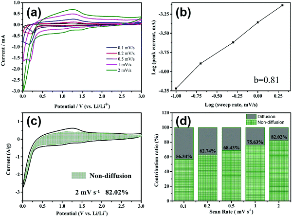
In order to calculate the contributions of the non-diffusion-controlled process and diffusion-controlled process to the total storage capacity of lithium ions under different current densities, the CV of the MnO2/MXene foam at different scanning rates was studied and the results are shown in Fig. 6(a). The current (I) and scanning rate (V s−1) follow the following formula
| i = avb |
When b is equal to 1, this indicates that a complete non-diffusion control capacitance behavior is formed by the surface Faraday redox reaction, and when b is equal to 0.5 this indicates the diffusion control capacitance behavior caused by Li ion insertion and transport. After curve fitting in Fig. 6(b), the b value is 0.81, showing that the electrode capacity is controlled by a mixture of diffusion-type and non-diffusion-type. In order to further analyze the contribution of the non-diffusion process control part to the gross capacity at a certain scan rate, the following equation is used to calculate it
4. Conclusion
The MnO2/MXene foam with an abundantly porous structure is prepared by annealing after vacuum filtration, and it has good flexibility and can be cut directly to be an electrode. Compared with the MnO2 and MXene foam, the MnO2/MXene foam has a better electrochemical performance. The discharge capacity of the initial cycle can reach 1203 mA h g−1 and the capacity can be maintained at about 600 mA h g−1 after 200 cycles. Moreover, the capacity of the electrode attenuates less at a large current and the capacity is about 350 mA h g−1 at 5 A g−1. The presence of the MnO2 nanoparticles expands the MXene lamellar spacing, provides tunnels for Li ion shuttling and accelerates the transport speed of Li ions, thus improving the rate capability of electrode. The existence of the MXene nanosheets can release the internal stress caused by the volume change of MnO2 during charging and discharging, preventing the breaking and failure of the electrode and promoting the cycling stability of the electrode. MXene–Ti3C2Tx has excellent electrical conductivity due to the existence of its C atomic layer, which also acts as a conductive skeleton in the composite structure electrode and decreases the electrical resistance of the hybrid structure electrode.Conflicts of interest
The authors state that there are no conflicts to declare.Acknowledgements
This work was supported by the Natural Science Foundation of China (NSFC) (No. 51772024) and the State Key Laboratory for Advanced Metals and Materials (No. 2019-Z13).References
- Y. Huang, H. Yang, Y. Zhang, Y. Zhang, Y. Wu, M. Tian, P. Chen, R. Trout, Y. Ma, T. Wu, Y. Wu and N. Liu, A safe and fast-charging lithium-ion battery anode using MXene supported Li3VO4, J. Mater. Chem. A, 2019, 7, 11250–11256 RSC.
- R. Cai, S. Guo, Q. Meng, S. Yang, H. L. Xin, X. Hu, M. Li, Y. Sun, P. Gao, S. Zhang, H. Dong, S. Lei, K. Kim, H. Zeng, L. Sun, F. Xu and Y. Zhu, Atomic-level tunnel engineering of todorokite MnO2 for precise evaluation of lithium storage mechanisms by in situ transmission electron microscopy, Nano Energy, 2019, 63, 103840 CrossRef CAS.
- P. Yu, G. Cao, S. Yi, X. Zhang, C. Li, X. Sun, K. Wang and Y. Ma, Binder-free 2D titanium carbide (MXene)/carbon nanotube composites for high-performance lithium-ion capacitors, Nanoscale, 2018, 1, 596–5913 Search PubMed.
- Y. Zhang, Z. Mu, J. Lai, Y. Chao, Y. Yang, P. Zhou, Y. Li, W. Yang, Z. Xia and S. Guo, MXene/Si@SiOx@C Layer-by-Layer Superstructure with Autoadjustable Function for Superior Stable Lithium Storage, ACS Nano, 2019, 13, 2167–2175 CAS.
- C. Chen, X. Xie, B. Anasori, A. Sarycheva, T. Makaryan, M. Zhao, P. Urbankowski, L. Miao, J. Jiang and Y. Gogotsi, MoS2-on-MXene Heterostructures as Highly Reversible Anode Materials for Lithium-Ion Batteries, Angew. Chem., 2018, 130, 1864–1868 CrossRef.
- D. Xu, K. Ma, L. Chen, Y. Hu, H. Jiang and C. Li, MXene interlayer anchored Fe3O4 nanocrystals for ultrafast Li-ion batteries. Chemical Engineering Science, Chem. Eng. Sci., 2020, 212, 115342 CrossRef.
- S. Niu, Z. Wang, M. Yu, M. Yu, L. Xiu, S. Wang, X. Wu and J. Qiu, MXene-Based Electrode with Enhanced Pseudocapacitance and Volumetric Capacity for Power-Type and Ultra-Long Life Lithium Storage, ACS Nano, 2018, 12, 3928–3937 CrossRef CAS PubMed.
- C. Wei, H. Fei, Y. Tian, Y. An, G. Zeng, J. Feng and Y. Qian, Room-Temperature Liquid Metal Confined in MXene Paper as a Flexible, Freestanding, and Binder-Free Anode for Next-Generation Lithium-Ion Batteries, Small, 2019, 15, 1903214 CrossRef CAS PubMed.
- Y. Yang, J. Lu, H. Yu, Y. Zhang, Y. Huang, Y. Huang, Y. Long, J. Su, X. Lv and Y. Wen, Hydrodynamic force-induced rapid assembly of mesoporous MnO/C hollow microtube as an anode material for lithium-ion batteries, Ceram. Int., 2019, 45, 22281–22291 CrossRef CAS.
- X. Hui, R. Zhao, P. Zhang, C. Li, C. Wang and L. Yin, Low-Temperature Reduction Strategy Synthesized Si/Ti3C2MXene Composite Anodes for High-Performance Li-Ion Batteries, Adv. Energy Mater., 2019, 9, 1901065 CrossRef.
- J. Liu, H. B. Zhang, R. Sun, Y. Liu, Z. Liu, A. Zhou and Z. Z. Yu, Hydrophobic, Flexible, and Lightweight MXene Foams for High-Performance Electromagnetic-Interference Shielding, Adv. Mater., 2017, 29, 1702367 CrossRef PubMed.
- B. Jia, W. Chen, J. Luo, Z. Yang, L. Li and L. Guo, Construction of MnO2 Artificial Leaf with Atomic Thickness as Highly Stable Battery Anodes, Adv. Mater., 2020, 32, 1906582 CrossRef CAS PubMed.
- J. H. Park, W. Y. Choi, S. Lee, T. Kim and J. W. Lee, Graphene intercalated free-standing carbon paper coated with MnO2 for anode materials of lithium ion batteries, Electrochim. Acta, 2020, 348, 136310 CrossRef CAS.
- L. Zhu, J. Lv, X. Yu, H. Zhao, C. Sun, Z. Zhou, Y. Ying and L. Tan, Further construction of MnO2 composite through in-situ growth on MXene surface modified by carbon coating with outstanding catalytic properties on thermal decomposition of ammonium perchlorate, Appl. Surf. Sci., 2020, 502, 144171 CrossRef CAS.
- D. Li, X. Chen, P. Xiang, H. Du and B. Xiao, Chalcogenated-Ti3C2X2 MXene (X = O, S, Se and Te) as a high-performance anode material for Li-ion batteries, Appl. Surf. Sci., 2020, 501, 144221 CrossRef CAS.
- Y. Su, J. Zhang, K. Liu, Z. Huang, X. Ren and C. Wang, Simple synthesis of a double-shell hollow structured MnO2@TiO2 composite as an anode material for lithium ion batteries, RSC Adv., 2017, 7, 46263–46270 RSC.
- J. Ai, Y. Lei, S. Yang, C. Lai and Q. Xu, SnS nanoparticles anchored on Ti3C2 nanosheets matrix via electrostatic attraction method as novel anode for lithium ion batteries, Chem. Eng. J., 2019, 357, 150–158 CrossRef CAS.
- J. Zhou, S. Lin, Y. Huang, P. Tong, B. Zhao, X. Zhu and Y. Sun, Synthesis and lithium ion storage performance of two-dimensional V4C3 MXene, Chem. Eng. J., 2019, 373, 203–212 CrossRef CAS.
- A. L. M. Reddy, M. M. Shaijumon, S. R. Gowda and P. M. Ajayan, Coaxial MnO2/Carbon Nanotube Array Electrodes for High-Performance Lithium Batteries, Nano Lett., 2009, 9, 1002–1006 CrossRef CAS.
- S. Liu, X. Liu, J. Zhao, Z. Tong, J. Wang, X. Ma, C. Chi, D. Su, X. Liu and Y. Li, Three dimensional hierarchically porous crystalline MnO2 structure design for a high rate performance lithium-ion battery anode, RSC Adv., 2016, 6, 85222–85229 RSC.
- Y. Xue, Y. Li, G. Luo, K. Shi, E. Liu and J. Zhou, Using a Dynamic Inhibition Concept to Achieve Content-Controllable Synthesis of N-Coordinated Cu Atoms as Reversible Active Site toward Super Li-Ion Capacitors, Adv. Energy Mater., 2020, 10, 2002644 CrossRef CAS.
- Z. Ma, X. Zhou, W. Deng, D. Lei and Z. Liu, 3D Porous MXene (Ti3C2)/Reduced Graphene Oxide Hybrid Films for Advanced Lithium Storage, ACS Appl. Mater. Interfaces, 2018, 10, 3634–3643 CrossRef CAS PubMed.
- H. Liu and Y. Cui, A green and facile hydrothermal synthesis of γ-MnOOH nanowires as a prospective anode material for high power Li-ion batteries, J. Alloys Compd., 2019, 797, 334–340 CrossRef CAS.
- S. Chen, Y. Xiang, W. Xu and C. Peng, A novel MnO2/MXene composite prepared by electrostatic self-assembly and its use as an electrode for enhanced supercapacitive performance, Inorg. Chem. Front., 2019, 6, 199–208 RSC.
- H. Jiang, Z. Wang, Q. Yang, M. Hanif, Z. Wang, L. Dong and M. Dong, A novel MnO2/Ti3C2Tx MXene nanocomposite as high performance electrode materials for flexible supercapacitors, Electrochim. Acta, 2018, 290, 695–703 CrossRef CAS.
- Z. Li, X. Lian, M. Wu, F. Zheng, Y. Gao and H. Niu, A novel self-assembled-derived 1D MnO2@Co3O4 composite as a high-performance Li-ion storage anode material, Dalton Trans., 2020, 49, 6644–6650 RSC.
- Y. Liu, P. Zhang, N. Sun, B. Anasori, Q. Zhu, H. Liu, Y. Gogotsi and B. Xu, Self-Assembly of Transition Metal Oxide Nanostructures on MXene Nanosheets for Fast and Stable Lithium Storage, Adv. Mater., 2018, 30, 1707334 CrossRef PubMed.
- D. Zuo, S. Song, C. An, L. Tang, Z. He and J. Zheng, Synthesis of sandwich-like structured Sn/SnOx@MXene composite through in-situ growth for highly reversible lithium storage, Nano Energy, 2019, 62, 401–409 CrossRef CAS.
- H. Shi, C. J. Zhang, P. Lu, Y. Dong, P. Wen and Z. Wu, Conducting and Lithiophilic MXene/Graphene Framework for High-Capacity, Dendrite-Free Lithium-Metal Anodes, ACS Nano, 2019, 13, 14308–14318 CrossRef CAS PubMed.
- H. Liu, K. Cao, W. Li, Q. Han, R. Zheng, J. Shu, Z. Zhang, K. Huang, Q. Jing and L. Jiao, Constructing hierarchical MnO2/Co3O4 heterostructure hollow spheres for high-performance Li-Ion batteries, J. Power Sources, 2019, 437, 226904 CrossRef CAS.
- Y. Zhu, K. Rajouâ, S. Le Vot, O. Fontaine, P. Simon and F. Favier, Modifications of MXene layers for supercapacitors, Nano Energy, 2020, 73, 104734 CrossRef CAS.
- S. Zhang, Z. Zhang, J. Kang, Q. Huang, Z. Yu, Z. Qiao, Y. Deng, J. Li and W. Wang, Double-shelled nanoporous NiO nanocrystal doped MnO/Ni network for high performance lithium-ion battery, Electrochim. Acta, 2019, 320, 134542 CrossRef CAS.
- D. Narsimulu, S. Ghosh, M. Bhar and S. K. Martha, Electrochemical Studies on Kinetics and Diffusion of Li-Ions in MnO2 Electrodes, J. Electrochem. Soc., 2019, 166, A2629–A2635 CrossRef CAS.
- X. Zhao, H. Xu, Z. Hui, Y. Sun, C. Yu, J. Xue, R. Zhou, L. Wang, H. Dai, Y. Zhao, J. Yang, J. Zhou, Q. Chen, G. Sun and W. Huang, Electrostatically Assembling 2D Nanosheets of MXene and MOF-Derivatives into 3D Hollow Frameworks for Enhanced Lithium Storage, Small, 2019, 15, 1904255 CrossRef CAS PubMed.
- Y. Wang, X. Wang, X. Li, Y. Bai, H. Xiao, Y. Liu, R. Liu and G. Yuan, Engineering 3D Ion Transport Channels for Flexible MXene Films with Superior Capacitive Performance, Adv. Funct. Mater., 2019, 29, 1900326 CrossRef.
- Q. Zhao, Q. Zhu, J. Miao, P. Zhang, P. Wan, L. He and B. Xu, Flexible 3D Porous MXene Foam for High-Performance Lithium-Ion Batteries, Small, 2019, 15, 1904293 CrossRef CAS PubMed.
Footnote |
| † Electronic supplementary information (ESI) available. See DOI: 10.1039/d1ma00488c |
| This journal is © The Royal Society of Chemistry 2021 |

