 Open Access Article
Carbon-MEMS based rectangular channel microarrays embedded pencil trace for high rate and high-performance lithium-ion battery application†
Ananya
Gangadharan
,
Suresh
Kali
,
Suresh
Mamidi
 *,
Anil D.
Pathak
and
Chandra S.
Sharma

Creative & Advanced Research Based On Nanomaterials (CARBON) Laboratory, Department of Chemical Engineering, Indian Institute of Technology Hyderabad, Kandi-502285, Sangareddy, Telangana, India. E-mail: ch14m16p000003@iith.ac.in
First published on 27th September 2021
Abstract
The miniaturization of a lithium-ion battery has been an aspiration in portable electronic devices and a possible method of implementation is by changing the electrode configuration from a 2D system to a 3D one. A carbon microelectromechanical system is a plausible execution of lithium-ion storage from 2D carbon films to 3D structures. However, the use of semiconducting silicon as a substrate for 3D structures and dendrite formation are hurdles. The present work describes the fabrication of 3D carbon rectangular channels on a pencil-traced stainless steel current collector and its utilization as the anode in a lithium-ion battery. Detailed physical and electrochemical studies demonstrate the advantage of this electrode in terms of reversible storage capacity and the establishment of a low resistance path for an electrochemical reaction. The cell exhibits an extraordinary capacity of 2000 mA h g−1 at 150 mA g−1 and it retained a capacity of ∼400 mA h g−1 even at 10![[thin space (1/6-em)]](https://www.rsc.org/images/entities/char_2009.gif) 000 mA g−1 after 1750 cycles. Also, the full-cell prototype further proves the potency of this electrode. Additionally, the time-dependent Li-ion concentration gradient across the 3D carbon rectangular channels is estimated using a diffusion-limited model. These simulation studies clearly suggest that Li-ion diffusion is more favorable in 3D carbon rectangular channels than in 2D films.
000 mA g−1 after 1750 cycles. Also, the full-cell prototype further proves the potency of this electrode. Additionally, the time-dependent Li-ion concentration gradient across the 3D carbon rectangular channels is estimated using a diffusion-limited model. These simulation studies clearly suggest that Li-ion diffusion is more favorable in 3D carbon rectangular channels than in 2D films.
1. Introduction
The miniaturization of portable electronic devices is demanded for high storage capacity compact batteries.1 In this regard, the replacement of the conventional planar geometry of the electrode with three-dimensional (3D) microarrays can be a remedial approach.2–4 The carbon microelectromechanical system (CMEMS) opens up a new avenue for various three-dimensional carbon geometries on a substrate. Marc Madou et al. introduced the concept of CMEMS and reported different 3D geometries on a silicon substrate.5,6 These carbon structures were explored in various electrochemical applications, such as batteries, supercapacitors, fuel cells, sensors, and solar cells.2,7–14 Wang et al. derived high aspect ratio carbon posts by the pyrolysis of a negative photoresist and verified the aptness of these carbon structures for a reversible lithium-ion intercalation/deintercalation process.2Further, F. Galobardes et al. investigated the formation of a solid electrolyte interface (SEI) on the CMEMS anode and the attribution to it of large irreversible capacity and charge transfer resistance.15 Hong Soek Min et al. extended CMEMS fabrication by creating positive electrode arrays of dodecylbenzene sulfonate doped polypyrrole (PPYDBS) on carbon posts using an electrochemical deposition technique. Their group successfully fabricated a prototype of a 3D C/PPYDBS full cell on a silicon substrate with a capacity of 10.6 μA h cm−2. However, its operation was limited due to an electrical short.4 Another turning point was the fabrication of cross-shaped CMEMS arrays, and the realization of their advantages over conventional carbon posts and the group proposed that cross-shaped CMEMS with thinner features are favorable for the better utilization of carbon.14
The concept of 3D carbon structures has been explored in many ways rather than building only pyrolyzed SU-8 carbon posts on a silicon substrate. Different types of carbon structures are integrated with the SU-8 carbon posts and RF gel derived carbon posts. Sharma et al. reported RF gel derived 3D cross-shaped and cylindrical shaped geometries and suspended SU-8 carbon nanofiber over carbon posts by a simple and efficient electrospinning method.16 Other reports show carbon nanowire integrated CMEMS;17 binder-free advanced matrix nanostructured electrodes;18 and the integration of SWNT/MWNT on carbon posts.19 A few reports show thin film deposition on the carbon posts by a sputtering method.20,21 However, the growth of the 3D carbon structures on a semiconducting silicon substrate is an issue for faster electron conduction in electrochemical storage devices. Therefore, our group optimized the parameters for the growth of high aspect ratio 3D carbon posts on a stainless steel (SS) substrate instead of a silicon substrate.11 From our previous study, we observed a dramatic increment in the capacity with cycle number without stabilization, resulting in a fall in the Coulombic efficiency of the battery.11 We scrutinized the electrochemical behavior of these batteries and summed up the possible reasons, which are: (i) lithium-ion reversibility in the high aspect ratio 3D carbon posts in vertical alignment is not efficient; (ii) there can be a direct contact of lithium ions with the substrate material, that can lead to malfunctioning of the battery; and (iii) inefficient utilization of the 3D carbon posts for reversible lithium-ion storage. To address these issues, in the present work, we fabricated an electrode with horizontally aligned high aspect ratio rectangular carbon channels on pencil-traced (graphite-coated) stainless-steel current collector (of a 2032 coin cell) for feasible lithium-ion storage. These rectangular channels can be more advantageous than a cylindrical carbon post geometry due to the direct interaction of lithium ions with the larger surface area of the electrode with the shortest diffusion path. Moreover, we found that the pencil-traced graphite layer avoids the direct contact of lithium ions with the stainless steel (SS) substrate through the embedded space between each channel. In this way, this thin layer of pencil-traced graphite simultaneously acts as a barricade against dendrite formation and a reversible storage material for lithium ions. Therefore, the as-fabricated lithium-ion battery using this 3D rectangular channel geometry as an anode material exhibited excellent electrochemical performance in the half-cell as well as in full-cell prototype. In the half-cell configuration, the cell delivered an extraordinary capacity of around 2000 mA h g−1 and 600 mA h g−1 at current densities of 150 and 10![[thin space (1/6-em)]](https://www.rsc.org/images/entities/char_2009.gif) 000 mA g−1, respectively. After the rate capability (at various current densities of 150, 200, 500, 1000, 2000, 5000, 10
000 mA g−1, respectively. After the rate capability (at various current densities of 150, 200, 500, 1000, 2000, 5000, 10![[thin space (1/6-em)]](https://www.rsc.org/images/entities/char_2009.gif) 000 mA g−1) and stability test for 1750 cycles (at a current density of 10
000 mA g−1) and stability test for 1750 cycles (at a current density of 10![[thin space (1/6-em)]](https://www.rsc.org/images/entities/char_2009.gif) 000 mA g−1) the cell retained 80% of its initial capacity. To the best of our knowledge, this is the only 3D based anode that exhibited a high capacity of 114 μA h cm−2 and that too at high current density in the full-cell prototype. Finite element-based COMSOL Multiphysics simulations were performed to analyse and establish the ease of Li-ion diffusion in 3D carbon rectangular channels.
000 mA g−1) the cell retained 80% of its initial capacity. To the best of our knowledge, this is the only 3D based anode that exhibited a high capacity of 114 μA h cm−2 and that too at high current density in the full-cell prototype. Finite element-based COMSOL Multiphysics simulations were performed to analyse and establish the ease of Li-ion diffusion in 3D carbon rectangular channels.
2. Experimental section
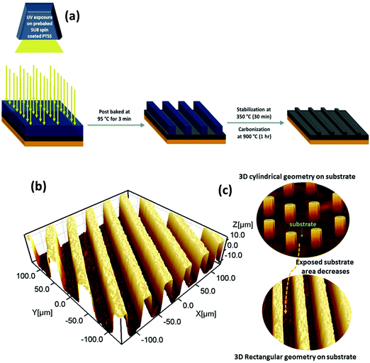
An array of horizontally aligned high aspect ratio 3D rectangular channels of carbon has been designed for fabrication on a pencil-traced (graphite-coated) stainless steel substrate. For a 2032-coin cell, a stainless steel current collector of 12 mm diameter was chosen as a substrate. Further, the surface of the steel substrate was deliberately coarsened with emery paper (paper no:120) and washed thoroughly with DI water and alcohol to remove the impurities. The coarsened surface of the steel substrate was rubbed with a graphite pencil to obtain a uniform graphite layer over it; later it was named a pencil-traced modified stainless steel substrate (PTSS). An epoxy-based negative photoresist, SU-8 2015 (purchased from Microchem Corp., USA) was spin-coated on PTSS at 3000 rpm speed for 30 s followed by pre-baking at 95 °C for 2 min and 30 s to remove excess solvent. We used a mask-less photolithography approach to fabricate 3D rectangular patterns from the photo-resist. To attain these 3D patterned structures, a photolithography tool equipped with a UV light source (with a wavelength of 365 nm) and an in-built optical grating set-up (Intelligent Micro Patterning, LLC Model no: SF-100 Xpress) were used. A pre-baked photoresist-coated PTSS substrate was subjected to UV exposure (selective exposure) for 25 s to allow the epoxy to endure polymerization through the cross-linking process. This exposed sample was baked at 95 °C for 3 min and washed carefully with a commercially available developer solution for 1 min and 30 s. During this washing process, UV-unexposed areas will be solubilized into the solution and only 3D rectangular microchannels will be left. The patterned sample was further hard-baked at 150 °C for 5 min and loaded into a horizontal tubular furnace for pyrolysis. This fabrication procedure is schematically depicted in Fig. 1(a). Before the heating process, the furnace chamber was purged with nitrogen gas at 75 lph for 30 min and further maintained at a flow rate of 20 lph throughout the pyrolysis process. We followed a two-step pyrolysis approach. Initially, the sample was stabilized at 350 °C (heating rate of 2 °C min−1) for a dwell time of 30 min. For the carbonization, the temperature of the furnace was later increased to 900 °C at a 5 °C min−1 ramp rate and the sample was maintained at this temperature for 1 h. The sample was collected once the furnace had cooled down to room temperature and it was labeled as 3D rectangular carbon channels on PTSS (3DRC-PTSS). Without any further treatment, the as-prepared 3DRC-PTSS was used as an anode during cell fabrication. The active material mass loading of the 3D carbon anode was measured to be 0.26 mg cm−2. To ensure the feasibility of electrode fabrication, we further fabricated the electrode with a UV flood exposure photolithography technique using a chrome mask instead of mask-less photolithography.2.1 Structural characterization
The morphological features of the pre-pyrolyzed and post-pyrolyzed patterned samples were studied using an optical microscope (Zeiss AxioCam) and a scanning electron microscope (Phenom ProX, operated at 5 kV). A 3D optical profiler (NanoMap-D) was used to measure the height distribution of the as-fabricated microchannel arrays. Raman spectra of 3DRC-PTSS were obtained by WiTec Raman spectroscopy with green laser excitation (532 nm, excitation energy of 2.33 eV).2.2 Electrochemical studies
2032-Coin cells were assembled inside a glove box (O2 < 0.1 ppm, H2O < 0.1 ppm) using 3DRC-PTSS as the working electrode and lithium foil as the counter/reference electrode while for the full-cell fabrication, LiFePO4 was used as the cathode. Whatman glass fiber filter paper was used as a separator and 1 M LiPF6 dissolved in ethylene carbonate (EC) and dimethyl carbonate (DMC) in a ratio of 1![[thin space (1/6-em)]](https://www.rsc.org/images/entities/char_2009.gif) :
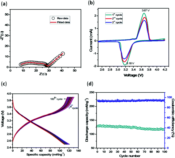
:![[thin space (1/6-em)]](https://www.rsc.org/images/entities/char_2009.gif) 1 (v/v%) was used as an electrolyte in the half-cell/full-cell assembly. Further electrochemical tests, cyclic voltammetry (CV), galvanostatic charge–discharge (GCD), and electrochemical impedance analysis (EIS) were conducted on these assembled cells using a Biologic VSP 300 electrochemical work station. GCD was performed in a potential window of 0.01 V to 3V for the half-cell and 2.5 to 3.9 V for the full cell. The EIS measurement was carried out in the frequency range 0.1 Hz to 1 MHz by applying a perturbation of 10 mV.
1 (v/v%) was used as an electrolyte in the half-cell/full-cell assembly. Further electrochemical tests, cyclic voltammetry (CV), galvanostatic charge–discharge (GCD), and electrochemical impedance analysis (EIS) were conducted on these assembled cells using a Biologic VSP 300 electrochemical work station. GCD was performed in a potential window of 0.01 V to 3V for the half-cell and 2.5 to 3.9 V for the full cell. The EIS measurement was carried out in the frequency range 0.1 Hz to 1 MHz by applying a perturbation of 10 mV.
3. Results and discussion
3.1 Fabrication of 3D rectangular channels on pencil-traced SS
For the growth of the 3D rectangular channels, a conventional silicon wafer substrate was replaced by a pencil-traced (graphite-coated) stainless steel current collector (PTSS). The surface of the steel substrate was deliberately coarsened with emery paper to provide good adhesion to the thin layer of coated graphite. This graphite coating can reduce the contact resistance between the active material and the SS substrate while cycling the cell and can also contribute as a storage material (a detailed description has been given in electrochemical studies). The spacing of the rectangular channels is important in determining the total active surface area on the substrate. This directly influences electrochemical performance. If the spacing is larger, then the number of 3D channels is less, which further reduces the areal capacity of the electrode. On the other hand, the minimum spacing between the rectangular channels is determined by the experimental limitations. Considering all the above, the spacing was determined as 20 μm for a 3D rectangular channel array. To understand the influence of these 3D rectangular channels on a pencil-traced SS substrate compared to conventional 3D carbon posts on a silicon wafer, the physical and electrochemical properties of this material were scrutinized.3.2 Profilometry: inspection of the empty spaces between the 3D rectangular structures when compared to cylindrical posts
The exposure of the substrate (current collector) to the electrolyte has to be controlled to achieve a maximum material surface (3D surface) for the electrochemical reaction. Therefore, the 3D structures must be tightly packed with minimum substrate exposure; thereby the direct contact of lithium ions with the substrate can be avoided. Fig. 1(b) depicts the three-dimensional profilometry of the equally spaced rectangular geometry of the fabricated 3D channels. The structure exhibited uniformity with straight walls and an excellent edge profile. The average height of the channel in 3D RC-PTSS is 15 ± 2 μm and the width and spacing between the rectangular channels are 20 ± 5 μm. The importance of this geometry is that the 3D rectangular channel reduces the exposure of the substrate (current collector) to the electrolyte compared to carbon posts. The maximum area of the circular substrate is covered by this 3D geometry and the remaining exposed area is graphite coated. Therefore, the direct exposure of the SS substrate area to the electrolyte is eliminated compared to the cylindrical carbon post geometry on an SS/silicon substrate. Fig. 1(c) schematically represents the reduction in substrate exposure.3.3 SEM and optical imaging
Optical microscope and SEM images, as shown in Fig. 2(a and b), provide a panoramic view of the 3D RC-PTSS. It shows an array of uniform 3D channel structures with consistency in channel width and spacing between channels. The width and spacing between the 3D channels are labeled in Fig. 2(a). The color contrast in the optical image (Fig. 2(a)) and SEM image (inset of Fig. 2(b)) verifies the 3D projection of the rectangular channels on the substrate. The obtained 3D pattern without any distortion shows that the penciled graphite layer could provide a good adhesive surface for the growth of the 3D structures. SEM and optical images provide a clear visualization of the grown 3DRC-PTSS. After cycling, the cell was dissassembled and the electrode was examined under SEM to verify the structural integrity of the 3D rectangular channels. Fig. S1 (ESI†) reveals that the 3D rectangular channel structure is stable and only a minor distortion was noticed.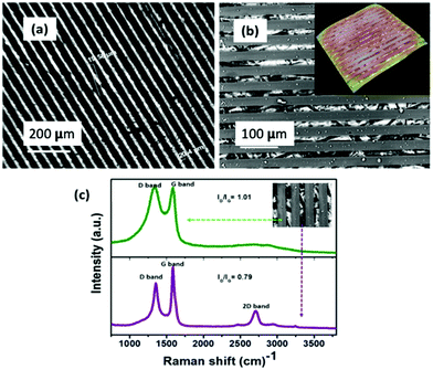 | ||
| Fig. 2 (a) Optical image of 3D-RCPTSS. (b) SEM image of 3D-RCPTSS; inset is the 3D constructed SEM image. (c) Raman spectra of 3D-RCPTSS. | ||
3.4 Raman spectroscopic analysis: scrutiny on substrate carbon and SU-8 derived carbon
To identify the nature of SU-8 derived carbon and pencil-traced carbon on the SS substrate, Raman spectra were collected from PTSS (graphite-coated area) and the top surface of the 3D RC-PTSS, respectively (Fig. 2(c)). The top surface of 3D RC-PTSS (SU-8 derived carbon) exhibits two characteristic peaks at ∼1330 cm−1 and ∼1590 cm−1 representing the A1g symmetry of disordered graphite and the E2g symmetry mode associated with the in-plane stretching of the sp2 bonded carbon atoms, respectively.22,23 These partially superimposed D and G bands with an ID/IG ratio ∼1 indicate the degree of disorder with a glassy carbon nature.11 While the Raman spectrum of penciled carbon (graphite-coated surface) shows well-defined D and G as well as 2D bands at ∼1350 cm−1, ∼1590 cm−1, and ∼2590 cm−1, respectively, which are the characteristic peaks of graphitic carbon. The ID/IG ratio of ∼0.79 also indicates the more graphitic nature of pencil-traced carbon. Therefore, we can say that the fabricated anode (3D-RCPTSS) is a combination of glassy carbon and graphitic carbon.3.5 Electrochemical properties
We identified the possible issues of a conventional 3D cylindrical carbon post electrode on an SS/silicon substrate (current collector) related to the electrochemical performance of the cell. The main issues are (1) irreversible capacity,24 (2) limited lithium-ion storage, (3) inefficient utilization of carbon pillars, and (4) lithium-ion–substrate interaction (schematically represented in Fig. 3(a) and (b)). Due to these severe setbacks, the cell miserably ended up in short circuiting or malfunctioning (a falling of the Coulombic efficiency of the cell). Therefore, fabricating 3D rectangular channels over PTSS instead of 3D cylindrical carbon posts aids in utilizing these 3D structures to their full potential as anode materials. The detailed electrochemical studies of 3D RC-PTSS, as described below, address all the issues related to conventional 3D pillars on silicon/SS substrates.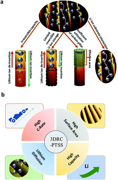 | ||
| Fig. 3 (a) Schematic representation of the issues related to a conventional cylindrical carbon post electrode. (b) Advantages of 3D microelectrodes channels over planar electrodes. | ||
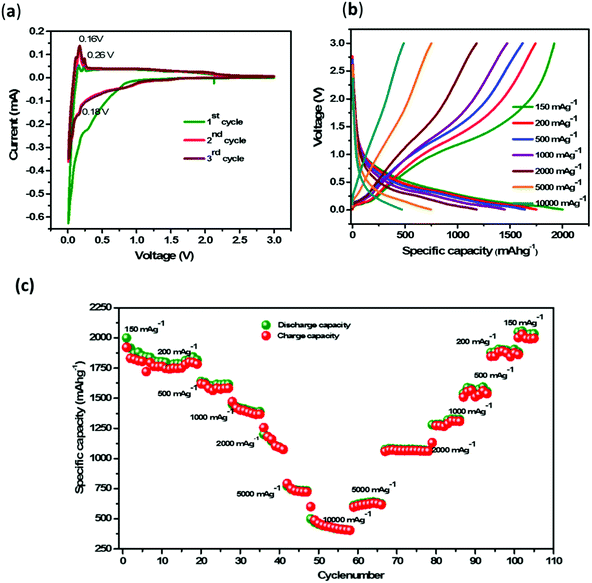
Moreover, the distinct peak positions and their repeatability in the anodic scan represent the lithium-ion storage in the pencil lead graphite by the intercalation/de-intercalation method. These peaks are due to the staged transformation of lithium–graphite intercalation compounds of LiC24, LiC12, and LiC6 at the PTSS base of 3DRC-PTSS, respectively.28–30 This is further clarified by the CV of the cell with only PTSS (graphite-coated SS) as the anode presented in Fig. S2 (ESI†). The CV analysis shows that 3D RC-PTSS has a larger electrochemical surface area than that of PTSS alone, which emphasizes lithium-ion storage in the glassy carbon. It is also proof of reversible lithium-ion storage in penciled graphite as well as 3D glassy carbon rectangular channels in 3DRC-PTSS. This result is evidence for the direct interaction of lithium ions with the substrate material through the embedded space between the 3D structures. In other words, if the SS substrate (current collector) is not pencil traced with graphite, there will be a direct interaction of lithium ions with the SS substrate (current collector) that can cause dendrite formation and ultimately shorting of the battery.
![[thin space (1/6-em)]](https://www.rsc.org/images/entities/char_2009.gif) 000 mA g−1 (Fig. 4(b)). The charging and discharging of the battery at a low current rate provide information regarding the maximum utilization of the anode material as well as the efficiency of the battery to deliver current to the load. The cell cycled at different current densities 150, 200, 500, 1000, 2000, 5000 and 10
000 mA g−1 (Fig. 4(b)). The charging and discharging of the battery at a low current rate provide information regarding the maximum utilization of the anode material as well as the efficiency of the battery to deliver current to the load. The cell cycled at different current densities 150, 200, 500, 1000, 2000, 5000 and 10![[thin space (1/6-em)]](https://www.rsc.org/images/entities/char_2009.gif) 000 mA g−1 exhibited capacities of 2000, 1750, 1645, 1451, 1183, 746 and 484 mA h g−1, respectively. The capacity retention of 2034 mA h g−1 at 150 mA g−1 after cycling at 10
000 mA g−1 exhibited capacities of 2000, 1750, 1645, 1451, 1183, 746 and 484 mA h g−1, respectively. The capacity retention of 2034 mA h g−1 at 150 mA g−1 after cycling at 10![[thin space (1/6-em)]](https://www.rsc.org/images/entities/char_2009.gif) 000 mA g−1 shows the applicability of the cell at a low current rate as well as a high current rate (Fig. 4(c)). This electrochemical response shows that there is no malfunctioning of the battery either at high or at low current densities due to the substrate protection from lithium plating by the pencil lead graphite coating.
000 mA g−1 shows the applicability of the cell at a low current rate as well as a high current rate (Fig. 4(c)). This electrochemical response shows that there is no malfunctioning of the battery either at high or at low current densities due to the substrate protection from lithium plating by the pencil lead graphite coating.
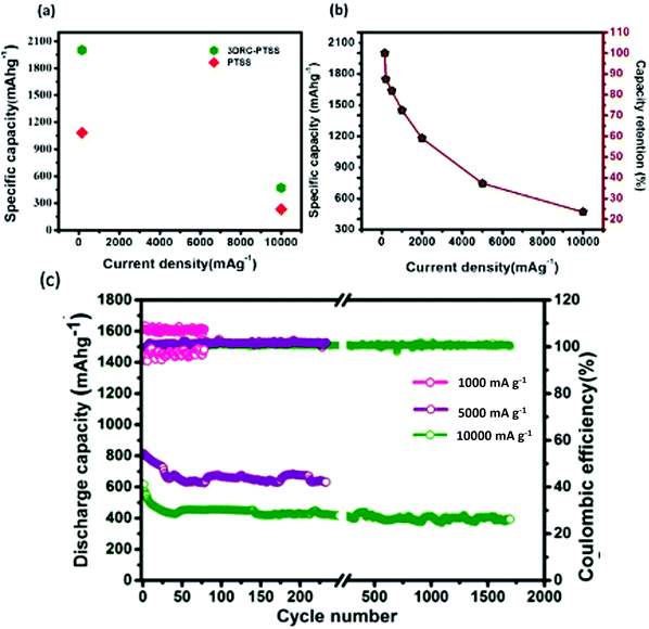
![[thin space (1/6-em)]](https://www.rsc.org/images/entities/char_2009.gif) 000 mA g−1, respectively, whereas PTSS showed capacities of 1080 and 228 mA h g−1, respectively. In addition, Fig. 5(b) shows that when the current increases from 150 to 10
000 mA g−1, respectively, whereas PTSS showed capacities of 1080 and 228 mA h g−1, respectively. In addition, Fig. 5(b) shows that when the current increases from 150 to 10![[thin space (1/6-em)]](https://www.rsc.org/images/entities/char_2009.gif) 000 mA g−1 (almost a 67 times increment in current density), the cell could retain 25% of its capacity. This observation undeniably proves the role of 3D RC structures in the fast-reversible lithium-ion storage mechanism. Further, compared to the reported capacity values and cycle life (550 mA h g−1) at 0.1 C (100 cycles),32 220 mA h g−1 at 0.5828 mA (9 cycles),33 ∼200 mA h g−1 at 76.4 μA cm−2 (6 cycles),14 596 mA h g−1 at 37.2 mA g−1 (160 cycles),11 the cylindrical 3D structures on penciled SS reported a capacity of 538 mA h g−1 at 500 mA g−1 (100 cycles34). For further confirmation, cylindrical carbon structures were fabricated on SS and penciled SS and the electrochemical data are given in Fig. S5a and b (ESI†), respectively. The cell exhibited capacities of 100 and 900 mA h g−1, respectively. When compared to a previous report11 as well as carbon posts on SS and pencil-traced SS, we observed that 3DRC-PTSS showed its supremacy both in capacity and in capacity retention. This could be due to the large surface area that is accessible for lithium-ion storage with the shortest diffusion path while cycling the cell.
000 mA g−1 (almost a 67 times increment in current density), the cell could retain 25% of its capacity. This observation undeniably proves the role of 3D RC structures in the fast-reversible lithium-ion storage mechanism. Further, compared to the reported capacity values and cycle life (550 mA h g−1) at 0.1 C (100 cycles),32 220 mA h g−1 at 0.5828 mA (9 cycles),33 ∼200 mA h g−1 at 76.4 μA cm−2 (6 cycles),14 596 mA h g−1 at 37.2 mA g−1 (160 cycles),11 the cylindrical 3D structures on penciled SS reported a capacity of 538 mA h g−1 at 500 mA g−1 (100 cycles34). For further confirmation, cylindrical carbon structures were fabricated on SS and penciled SS and the electrochemical data are given in Fig. S5a and b (ESI†), respectively. The cell exhibited capacities of 100 and 900 mA h g−1, respectively. When compared to a previous report11 as well as carbon posts on SS and pencil-traced SS, we observed that 3DRC-PTSS showed its supremacy both in capacity and in capacity retention. This could be due to the large surface area that is accessible for lithium-ion storage with the shortest diffusion path while cycling the cell.
The rate capability test signifies the ability of 3DRC-PTSS to work equally well in a higher current density range. Therefore the stability test of the cell was performed at 1000, 5000, and 10![[thin space (1/6-em)]](https://www.rsc.org/images/entities/char_2009.gif) 000 mA g−1 for 150, 250, and 1750 cycles, respectively (Fig. 5(c)). The cell could deliver a capacity of ∼400 mA h g−1 at 10000 mA g−1 (after 1750 cycles), 700 mA h g−1 at 5000 mA g−1 (after 250 cycles), and 1400 mA h g−1 at 1000 mA g−1 (after 150 cycles), respectively. The long cyclic life of the battery at different current densities without shorting or malfunctioning substantiates the potential of 3DRC-PTSS as anode material.
000 mA g−1 for 150, 250, and 1750 cycles, respectively (Fig. 5(c)). The cell could deliver a capacity of ∼400 mA h g−1 at 10000 mA g−1 (after 1750 cycles), 700 mA h g−1 at 5000 mA g−1 (after 250 cycles), and 1400 mA h g−1 at 1000 mA g−1 (after 150 cycles), respectively. The long cyclic life of the battery at different current densities without shorting or malfunctioning substantiates the potential of 3DRC-PTSS as anode material.
Similarly, RSEI and CPESEI indicate the impedance due to SEI layer formation, and RCT and CPECT measure the impedance involved in the charge transfer reaction.35–37 The calculated RSEI and RCT values are 19 Ω and 4.5 Ω, respectively, which implies that the cell provides minimum resistance for charge transfer. The SEI layer resistance is higher than the charge transfer resistance. This may be due to the resistance involved due to layer formation on the glassy carbon channels and penciled graphite. These impedance values are negligibly small when compared to the reported impedance values in the range of hundreds and thousands of ohms and clearly show the advantage of the 3DRC-PTSS electrode over conventional silicon substrate grown 3D structures.14,15 The faster reaction kinetics of the cell with capacity retention reveals that SEI acts as a good passivation layer for lithium ions. The appearance of a small diffusion line represented by a constant phase element (semi-infinite diffusion) further proves that the lithium-ion diffusion process is reasonably good.
3.6 Li-ion diffusion model
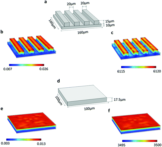
The finite element method (FEM) based diffusion model on the COMSOL simulation platform was carried out to examine the variation in Li-ion concentration across the 3D carbon rectangular channels with respect to time. To perform the Li-ion diffusion studies, we considered two cases: (i) 3D morphology of rectangular channels and (ii) the equivalent volume of flat (2D) electrodes. Further, a comprehensive comparative study for both cases was done to investigate the concentration gradients, as depicted in Fig. 7. In this study, we modeled the lithium-ion diffusion across the electrode by using Fick's Second Law of diffusion, as described in eqn (1).38 Here, the preliminary assumption is that the change in Li-ion concentration is mainly due to the concentration gradient and the other term (migration and source reaction) is negligible. | (1) |
In order to make the conditions of the simulation study closer to the experimental, the following measures were taken. (i) A more accurate replica of model geometry was constructed (Fig. 7(a)) based on the optical profiler data (Fig. 1(b)) of the real system. (ii) The experimental current density was used to calculate the flux boundary condition, as given in eqn (2).39,40
 | (2) |
The effective diffusion coefficient of 3D carbon rectangular channels was calculated using EIS data, as discussed in the literature.41,42 The calculated diffusion coefficient for the 3D carbon rectangular channels electrode is 1.44 × 10⁻⁸ m2 s−1. Fig. 7(b) shows the Li-ion concentration (0.026 mol m−3) in a 3D carbon rectangular channel after 0.1 s and its increase to 6120 mol m−3 after 60 min (Fig. 7(c)). The change in Li-ion concentration of the 2D flat electrode with an equivalent volume of 3D carbon rectangular channels was also modeled, as shown in (Fig. 7(d)). After 60 min, Li-ion concentration in a 2D flat electrode increased from 0.013 mol m−3 (Fig. 7(e)) to 3500 mol m−3 (Fig. 7(f)). The maximum Li-ion concentration after 60 min in both cases was found to be 6120 mol m−3 and 3500 mol m−3 for 3D rectangular channels and 2D flat electrode morphology, respectively. This clearly indicates that the 3D carbon rectangular channels enabled effective Li-ion diffusion compared to the 2D flat electrode.
4. Conclusions
We introduced a unique three-dimensional rectangular channel geometry on a pencil-traced stainless steel current collector to avoid the malfunctioning of the battery due to direct contact of lithium ions with the SS substrate as well as to maximize the capacity with a minimum lithium-ion diffusion path length and minimum substrate exposure. We observed the successful growth of 3D structures on pencil-traced SS due to the excellent adhesion of SU-8 polymer with the graphite layer, which after pyrolysis yielded 3D carbon rectangular channels without any structural damage. These rectangular geometries provided a larger surface area for the electrochemical reaction by decreasing the direct substrate exposure to the electrolyte and, therefore, showed its advantages over cylindrical carbon posts on the substrate, which are typically shown as 3D electrodes in the literature. From a battery perspective, 3DRC-PTSS exhibited outstanding electrochemical performance in half-cell as well as in full-cell configurations. The cell showed excellent lithium-ion storage characteristics and, more importantly, in lower as well as higher current densities. At 150 mA g−1, the cell exhibited a reversible capacity of 2000 mA h g−1 and ∼400 mA h g−1 at as high as 10 A g−1 current density. This could be due to the synergetic effect of pencil-traced graphite along with the 3D carbon structures. Also, the full-cell study proves its potential to work at a high current by retaining a capacity of 110 mA h g−1 (107.6 μAh cm−2) at 100 μA. The outcome of this work shows the plausible use of this anode material for the development of next-generation lithium-ion batteries.Conflicts of interest
There are no conflicts to declare.Acknowledgements
We acknowledge the financial support received from Ministry of Human Resources Development and Department of Heavy Industries, Govt. of India under IMPRINT scheme (Project 7035) to carry out this work.References
- C. Han, H. Li, Y. Li, J. Zhu and C. Zhi, Nat. Commun., 2021, 12, 2400 CrossRef CAS PubMed.
- C. Wang, L. Taherabadi, G. Jia, S. Kassegne, J. V. Zoval and M. J. Madou, MEMS, MOEMS, and Micromachining, 2004, vol. 5455, p. 295 Search PubMed.
- C. Wang, L. Taherabadi, G. Jia, M. Madou, Y. Yeh and B. Dunn, Electrochem. Solid-State Lett., 2004, 7, A435–A438 CrossRef CAS.
- H. S. Min, B. Y. Park, L. Taherabadi, C. Wang, Y. Yeh, R. Zaouk, M. J. Madou and B. Dunn, J. Power Sources, 2008, 178, 795–800 CrossRef CAS.
- B. Pramanick, M. Vazquez-Pinon, A. Torres-Castro, S. O. Martinez-Chapaa and M. Madou, Mater. Today Proc., 2018, 5, 9669–9682 CrossRef CAS.
- P. S. Ginestra, M. Madou and E. Ceretti, Precis. Eng., 2019, 55, 137–143 Search PubMed.
- C. Wang, R. Zaouk, B. Y. Park and M. J. Madou, Int. J. Manuf. Technol. Manage., 2008, 13, 360 Search PubMed.
- H. A. Rouabah, B. Y. Park, R. B. Zaouk, H. Morgan, M. J. Madou and N. G. Green, J. Micromech. Microeng., 2011, 21(3), 035018 Search PubMed.
- J. I. Heo, D. S. Shim, G. T. Teixidor, S. Oh, M. J. Madou and H. Shin, J. Electrochem. Soc., 2011, 158, J76 Search PubMed.
- R. R. Kamath and M. J. Madou, Anal. Chem., 2014, 86, 2963–2971 Search PubMed.
- S. Mamidi, M. Kakunuri and C. S. Sharma, ECS Trans., 2018, 85, 21–27 Search PubMed.
- S. Jiang, F. Wang, X. Tan, J. Lin, G. Liao, Z. Tang, T. Shi and L. Qian, Electrochim. Acta, 2019, 303, 323–328 Search PubMed.
- Y. Wang, L. Pham, G. P. S. de Vasconcellos and M. Madou, J. Power Sources, 2010, 195, 4796–4803 Search PubMed.
- G. T. Teixidor, R. B. Zaouk, B. Y. Park and M. J. Madou, J. Power Sources, 2008, 183, 730–740 Search PubMed.
- F. Galobardes, C. Wang and M. Madou, Diamond Relat. Mater., 2006, 15, 1930–1934 Search PubMed.
- C. S. Sharma, H. Katepalli, A. Sharma and M. Madou, Carbon, 2010, 49, 1727–1732 Search PubMed.
- S. Sharma, A. Sharma, Y. K. Cho and M. Madou, ACS Appl. Mater. Interfaces, 2012, 4, 34–39 Search PubMed.
- L. Zhang, X. Qin, S. Zhao, A. Wang, J. Luo, Z. L. Wang, F. Kang, Z. Lin and B. Li, Adv. Mater., 2020, 32, 1908445 Search PubMed.
- L. Zhang, T. Shi, S. Xi, D. Liu, Z. Tang, X. Li and W. Lai, Thin Solid Films, 2011, 520, 1041–1047 Search PubMed.
- Y. Gao, T. Shi, H. Zheng, Z. Tang and Q. Xia, Thin Solid Films, 2014, 550, 156–163 Search PubMed.
- Y. Gao, T. Shi, Z. Tang, S. Jiang and Q. Xia, Appl. Surf. Sci., 2014, 313, 687–691 Search PubMed.
- R. J. Nemanich and S. A. Solin, Phys. Rev. B: Condens. Matter Mater. Phys., 1979, 20, 392–401 Search PubMed.
- S. Reich and C. Thomsen, Philos. Trans. R. Soc. A Math. Phys. Eng. Sci., 2004, 362, 2271–2288 Search PubMed.
- W. Xing and J. R. Dahn, J. Electrochem. Soc., 1997, 144, 1195–1201 Search PubMed.
- P. Verma, P. Maire and P. Novak, Electrochim. Acta, 2010, 55, 6332–6341 Search PubMed.
- M. Winter, J. O. Besenhard, M. E. Spahr and P. Novák, Adv. Mater., 1998, 10, 725–763 Search PubMed.
- J. O. Besenhard, M. Winter, J. Yang and W. Biberacher, J. Power Sources, 1995, 54, 228–231 Search PubMed.
- M. D. Levi and D. Aurbach, J. Electroanal. Chem., 1997, 421, 79–88 Search PubMed.
- F. Ding, W. Xu, D. Choi, W. Wang, X. Li, M. H. Engelhard, X. Chen, Z. Yang and J.-G. G. Zhang, J. Mater. Chem., 2012, 22, 12745–12751 Search PubMed.
- M. Yoshio, H. Wang, K. Fukuda, Y. Hara and Y. Adachi, J. Electrochem. Soc., 2000, 147, 1245 Search PubMed.
- S. Mamidi, A. Gangadharan and C. S. Sharma, Electrochim. Acta, 2019, 310, 222–229 Search PubMed.
- S. Choi, J. I. Lee and S. Park, J. Mater. Chem., 2012, 22, 22366–22369 Search PubMed.
- C. Wang, G. Jia, L. H. Taherabadi and M. J. Madou, J. Microelectromech. Syst., 2005, 14, 348–358 Search PubMed.
- S. Mamidi, A. Gangadharan, A. D. Pathak, T. N. Rao and C. S. Sharma, ACS Appl. Energy Mater., 2020, 4(1), 545–553 Search PubMed.
- Z. Favors, H. H. Bay, Z. Mutlu, K. Ahmed, R. Ionescu, R. Ye, M. Ozkan and C. S. Ozkan, Sci. Rep., 2015, 5, 1–7 Search PubMed.
- G. Ananya, N. Pranati and S. Ramaprabhu, Int. J. Hydrogen Energy, 2016, 41, 3974–3980 Search PubMed.
- S. Ramaprabhu, A. Gangadharan and R. Sripada, J. Mater. Chem. A, 2017, 5, 2784–2791 Search PubMed.
- P. Andrei, J. P. Zheng, M. Hendrickson and E. J. Plichta, J. Electrochem. Soc., 2010, 157, A1287 Search PubMed.
- S. Mamidi, A. D. Pathak, A. Gangadharan and C. S. Sharma, J. Power Sources, 2020, 473, 228600 Search PubMed.
- E. Martínez-Rosas, R. Vasquez-Medrano and A. Flores-Tlacuahuac, Comput. Chem. Eng., 2011, 35, 1937–1948 Search PubMed.
- H. Xia, L. Lu and G. Ceder, J. Power Sources, 2006, 159, 1422–1427 Search PubMed.
- N. Ding, J. Xu, Y. X. Yao, G. Wegner, X. Fang, C. H. Chen and I. Lieberwirth, Solid State Ionics, 2009, 180, 222–225 Search PubMed.
Footnote |
| † Electronic supplementary information (ESI) available. See DOI: 10.1039/d1ma00745a |
| This journal is © The Royal Society of Chemistry 2021 |

