 Open Access Article
Self-assembly of TiO2/ZIF-8 nanocomposites for varied photocatalytic CO2 reduction with H2O vapor induced by different synthetic methods†
Yan-Hong
Zou‡
,
Hai-Ning
Wang‡
 ,
Xing
Meng
 *,
Hong-Xu
Sun
and
Zi-Yan
Zhou
 *
*
School of Chemistry and Chemical Engineering, Shandong University of Technology, Zibo 255049, People's Republic of China. E-mail: mengxing837@foxmail.com
First published on 28th January 2021
Abstract
Photoreduction of carbon dioxide (CO2) provides an effective perspective for solving the energy crisis and environmental problems. Herein, two types of composite photocatalysts (TiO2/ZIF-8) based on ZIF-8 and TiO2 have been designed and synthesized with the help of the grinding method and the solid-synthesis method. Both composite photocatalysts are employed for the photocatalytic reduction of CO2. In composite photocatalysts prepared by the grinding method, ZIF-8 particles are distributed on the surface of TiO2, and provide extra available spaces for storing CO2, which is beneficial for improving their photoreduction performances. As a result, an enhanced CO formation rate of 21.74 μmol g−1 h−1 with a high selectivity of 99% is obtained for this family of composite photocatalysts via the solid–gas mode without photosensitizers and sacrificial agents. For comparison, the other family of composite photocatalysts synthesized via the solid-synthesis method possesses structures similar to ZIF-8, where TiO2 is encapsulated inside the framework of ZIF-8. This structural feature obstructs the contact between the active sites of TiO2 and CO2, and leads to lower activities. The best CO formation rate of this family is only 10.67 μmol g−1 h−1 with 90% selectivity. Both the structural features of the two families of photocatalysts are described to explain their differences in photoreduction performances. The experimental finding reveals that different synthetic approaches indeed result in diversified structures and varied photocatalytic performances. This work affords a new scalable and efficient approach for the rational design of efficient photocatalysts in the area of artificial photosynthesis.
1. Introduction
Carbon dioxide (CO2) is mainly produced by the continuous combustion of fossil fuels, and has become a kind of greenhouse gas, which plays an important role in global warming. The growing concerns about global warming induced by the increase of CO2 concentrations have drawn increasing attention in the CO2 capture and conversion. Naturally, various approaches have been developed to overcome this problem.1–10 Among the reported technologies, the conversion of CO2 into valuable chemical materials by means of efficient photocatalysts may be an effective strategy with the help of solar energy, which is likely to resolve global warming. So, the development of outstanding photocatalysts for the photocatalytic reduction of CO2 has become an active field of research.In the past few decades, various kinds of photocatalysts have been designed and synthesized, and contain molecular compounds, semiconductors, and others.11–30 Common problems of these photocatalysts are listed below: a high recombination of electron–hole pairs, poor CO2 adsorption ability, and others.
It is urgent to prepare new photocatalysts with improved separation of electron–hole pairs, and enhanced CO2 adsorption ability. Metal–organic frameworks (MOFs), as a new class of porous crystalline materials, are constructed from numerous metal ions and various organic linkers.31–35 This kind of porous materials possesses following advantages: structural tunability, ordered porous structures and large surface area. These excellent characteristics make MOFs widely explored in various fields, such as sensors, energy storage and catalysis36–42 However, it is in early stages that MOFs are employed as photocatalysts for reducing CO2. A limited number of MOFs, such as UiOs43–45 and MILs has made an attempt in this field. For example, a light-harvesting MOF, MIL-125–NH2 (Ti), serves as a photocatalyst and can convert CO2 into HCOOH.44 These covered examples reveal that the photocatalytic activity of the individual MOF is usually not very good. Recently, pioneering examples have demonstrated that the combination of semiconductors with MOFs may be a good choice to enhance the CO2 photoreduction efficiency. The resulting composite photocatalysts possess the advantages of each component (e.g., strong CO2 adsorption capacity of MOFs and good photocatalytic ability of semiconductors).46 For instance, Wang et al.47 covered a composite photocatalyst Co–ZIF-9/CdS with an enhanced CO2 photoreduction performance. Naturally, it is necessary to develop more composite photocatalysts based on MOFs and semiconductors with great performance. As far as we know, most of the photocatalysts based on MOFs and semiconductors have been prepared with the help of conventional solvothermal or hydrothermal or bulk solution or wet-chemistry methods,48 which require a multi-step process, long reaction time and large amount of solvents. In order to overcome the above problem, it could be very interesting to explore a simple and scalable synthetic approach to prepare MOF/semiconductor composite photocatalysts with improved photocatalytic performances. Directed by this idea, a facile synthetic method (the grinding method) is selected to fabricate TiO2/ZIF-8 composite photocatalysts within a few minutes. ZIF-8 is chosen because of its high surface area and good stability towards water, which can guarantee the simultaneous absorption of water and CO2, critical for the process of photoreducing CO2. Finally, a variety of composite photocatalysts based on ZIF-8 and TiO2 have been synthesized through this simple and efficient manner.
Up to now, most of the photocatalysts have been employed for the photoreduction of CO2via a solid–liquid mode in the presence of sacrificial agents (e.g., triethanolamine) as electron donors, which are toxic and high-cost. Recently, another reaction mode (solid–gas mode) was developed to overcome this problem because this reaction mode does not need photosensitizers and sacrificial agents. In this reaction mode, CO2 and H2O molecules directly surround the photocatalyst. Meanwhile, H2O offers protons and acts as a sacrificial agent. For example, Xiong et al.49 employed this mode to evaluate the activity of Cu3(BTC)2@TiO2 in the photoreduction of CO2, which can selectively convert CO2 into CH4. Based on the above considerations, herein, a series of composite photocatalysts based on ZIF-8 and TiO2 have been synthesized with the help of the grinding method. In this method, ZIF-8 particles are located at the surface of the TiO2 spheres, which avoids the accumulation of TiO2 spheres, and are responsible for storing CO2. The obtained composite photocatalysts are evaluated for their CO2 photoreduction performance via solid–gas mode without photosensitizers and sacrificial agents. The results show that the well-integrated structures prefer to enhance the CO2 photoreduction performance. As a result, an enhanced CO formation rate of 21.74 μmol g−1 h−1 with a great selectivity of 99% was obtained. In order to verify the influence of the synthesis method on the photocatalytic reduction of CO2, another series of composite photocatalysts have been synthesized via the solid-synthesis method. This series of photocatalysts possess a similar structure compared to ZIF-8, where TiO2 is encapsulated into the framework of ZIF-8. These structures are different from those of the photocatalysts obtained via the grinding method, and this structural feature hinders their CO2 photoreduction performances, leading to lower activities. In summary, the experimental results reveal that different synthetic approaches generate varied structures and photocatalytic performances, possibly due to their different structural characteristics. Furthermore, the possible mechanism of the CO2 photocatalytic reduction is also proposed.
2. Experimental section
2.1 Materials and instruments
All used reagents and solvents are commercially available and directly used. The used reagents are listed below: 2-methyl imidazole (2-IM), titanium tetraisopropanolate (Ti(OiPr)4), ethanol, 5% Nafion solution, zinc acetate dehydrate (Zn(oAc)2), sodium sulphate and terephthalic acid (TA). All reagents were purchased from Shanghai Macklin Biochemical Co., Ltd.Fourier transform infrared spectroscopy (FT-IR) spectra were recorded with a Thermo Nicolet 5700 using KBr pellets for the sample. X-ray powder diffraction patterns of the samples were recorded on a Bruker D8 Advance diffractometer with Cu Kα (λ = 1.5418 Å) radiation in the range of 5–70°. The morphology analysis of the synthesized samples was collected on a scanning electron microscope (SEM, Sirion 200) at an acceleration voltage of 10 kV. X-ray photoelectron spectroscopy (XPS) measurements were carried out on a scanning X-ray microprobe (K-Alpha, Thermo Scientific) with Al α radiation and the C 1s peak at 284.8 eV as the internal standard. The UV-Vis absorption spectrum was obtained on a UV-2550 spectrophotometer (Shimadzu, Japan). The CO2 adsorption/desorption measurements were conducted under the ambient condition of 298 K (ASAP 2020). Nitrogen adsorption–desorption isotherms were measured at 298 K on an ASAP 2460 instrument. Transmission electron microscopy (TEM) on a JEM-200CX apparatus was performed at an accelerating voltage of 200 kV.
2.2 Synthesis and preparations
2.3 General catalytic reduction
![[thin space (1/6-em)]](https://www.rsc.org/images/entities/char_2009.gif) :
:![[thin space (1/6-em)]](https://www.rsc.org/images/entities/char_2009.gif) 1). The photogenerated OH˙ would react with TA to generate 2-hydroxyterephthalic acid (TAOH), which could be used to detect the generated OH˙. After irradiation, the obtained sample is used for fluorescence measurements.
1). The photogenerated OH˙ would react with TA to generate 2-hydroxyterephthalic acid (TAOH), which could be used to detect the generated OH˙. After irradiation, the obtained sample is used for fluorescence measurements.
3. Results and discussion
3.1 Structure and morphology
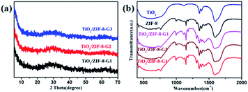
One family of TiO2/ZIF-8 composite photocatalysts has been prepared by the grinding method using an in situ synthetic process (experiment details in Experimental section), and is defined as TiO2/ZIF-8-GX (X = 1, 2 and 3, corresponding to the different volumes of used Ti(OiPr)4). For comparison, another family of TiO2/ZIF-8 composite photocatalysts was also prepared using the same reaction substrates with the help of the solid-synthesis method, namely ZIF-8/TiO2-SX (X = 1, 2 and 3, corresponding to the different volumes of used Ti(OiPr)4). In order to confirm the successful formation of ZIF-8 and TiO2, all as-synthesized powders have been identified via the powder X-ray diffraction (PXRD) patterns. The crystallinities of TiO2/ZIF-8-GX are not well-defined. Only several weak peaks (around 10.4°, 12.5° and 18.5°) are observed, which are consistent with the simulated PXRD pattern of ZIF-8 (Fig. 1a and S3†). In addition, there is a broad peak between 20° and 40° relative to TiO2, which can be attributed to the anatase TiO2 (JCPDS no. 21-1272).51 Additionally, the PXRD patterns of TiO2/ZIF-8-SX were performed. Their patterns exhibit good diffraction peaks, and match well with that of ZIF-8, implying that the good crystallinity of ZIF-8 is well maintained (Fig. S2†). It should be mentioned that a weak diffraction peak at 25.7° is responsible for the (101) plane of TiO2.In addition, the Fourier transform infrared (FT-IR) spectra were used to analyze the surface chemistry of the prepared TiO2/ZIF-8 composite photocatalysts. As shown in Fig. 1b and S1,† the spectra of TiO2/ZIF-8-GX and TiO2/ZIF-8-SX composite photocatalysts constructed by different approaches are similar. In Fig. 1b, their characteristic peaks are clearly found in the FTIR spectra. The peaks around 996, 1423 and 1578 cm−1 are attributed to the C–N and C![[double bond, length as m-dash]](https://www.rsc.org/images/entities/char_e001.gif) N stretching vibrations from 2-IM, and the signals of the C–N bending vibration are demonstrated by the peaks located at around 1148 and 1308 cm−1. Besides, the peak at 420 cm−1 in the spectra belongs to the stretching vibrations of the Zn–N bonds.52,53 Additionally, the broad peaks from 500 to 800 cm−1 are ascribed to the stretching vibrations of the Ti–O bonds.54,55 As shown in Fig. S1,† similar peaks are found in the spectra of TiO2/ZIF-8-SX. The signals of the C–N and C
N stretching vibrations from 2-IM, and the signals of the C–N bending vibration are demonstrated by the peaks located at around 1148 and 1308 cm−1. Besides, the peak at 420 cm−1 in the spectra belongs to the stretching vibrations of the Zn–N bonds.52,53 Additionally, the broad peaks from 500 to 800 cm−1 are ascribed to the stretching vibrations of the Ti–O bonds.54,55 As shown in Fig. S1,† similar peaks are found in the spectra of TiO2/ZIF-8-SX. The signals of the C–N and C![[double bond, length as m-dash]](https://www.rsc.org/images/entities/char_e001.gif) N stretching vibrations and the C–N bending vibrations are demonstrated by the peaks at around 998, 1421, 1582, 1145 and 1304 cm−1. The peak located at 424 cm−1 corresponds to the Zn–N bonds. The broad peaks at around 500–790 cm−1 belong to the Ti–O bond stretching vibration.
N stretching vibrations and the C–N bending vibrations are demonstrated by the peaks at around 998, 1421, 1582, 1145 and 1304 cm−1. The peak located at 424 cm−1 corresponds to the Zn–N bonds. The broad peaks at around 500–790 cm−1 belong to the Ti–O bond stretching vibration.
X-ray photoelectron spectroscopy (XPS) has been used to study the chemical states and the composition of the prepared photocatalysts. The survey spectrum of TiO2/ZIF-8-G2 proves the presence of the Zn 2p, Ti 2p, N 1s, C 1s and O 1s peaks (Fig. 2a). The XPS spectrum of Ti exhibits two peaks at 458.6 eV and 464.3 eV, which are relative to the binding energies of Ti 2p3/2 and Ti 2p1/2, respectively (Fig. 2b). This implies the existence of the oxidation state Ti4+ in TiO2/ZIF-8-G2. As seen in Fig. 2c, the binding energies at 1022.1 eV and 1045.1 eV belong to the Zn 2p3/2 and Zn 2p1/2, respectively. Fig. 2d shows that two peaks at around 284.7 eV and 288.5 eV are assigned to the C–C and C–N bonds from the imidazole groups in the C 1s spectrum, respectively. Additionally, in the spectrum of N, two peaks (399.3 and 400.9 eV) can be attributed to –NH– and C–N, respectively (Fig. 2e). In the O 1s spectrum, one main peak at 530.3 eV belongs to the Ti–O bonds, and the other peak with weak intensity at 531.6 eV is attributed to the lattice oxygen atoms in TiO2 (Fig. 2f).56,57 In summary, all characterization results indicate that the successful combination of TiO2 and ZIF-8 has been realized.
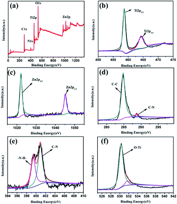 | ||
| Fig. 2 (a) XPS survey of TiO2/ZIF-8-G2, (b) Ti 2p, (c) Zn 2p, (d) C 1s, (e) N 1s and (f) O 1s spectra. | ||
The obtained photocatalysts have been used to evaluate their surface morphology with the help of scanning electron microscopy (SEM) images. The morphologies of ZIF-8, TiO2 and TiO2/ZIF-8-GX are found to be different by SEM images. The SEM images show that the particles of ZIF-8 possess the smooth surface and exhibit angular shapes (Fig. 3a and b). Fig. 3b shows that the as-synthesized TiO2 particles are spherical with rough surfaces. In addition, the pure TiO2 spheres can agglomerate together. As shown in Fig. 3c–e, most of the particles also maintain the sphere shape, but possess rougher surfaces, compared with that of the pure TiO2 spheres, indicating that the ZIF-8 particles have successfully coated the surfaces of the TiO2 spheres. The coating of ZIF-8 make TiO2/ZIF-8-GX greatly avoid the agglomeration of TiO2, which may enhance their catalytic activity. The elemental distribution of TiO2/ZIF-8-GX has been carried out with the help of element mapping. Fig. 3f clearly displays the element distribution of TiO2/ZIF-8-G2, where the cyan, red, grey, green and yellow colours represent the distributions of each element C, N, O, Ti and Zn, respectively. With the help of the element mapping, we can confirm that ZIF-8 was successfully located on the surface of the TiO2 spheres. Summarily, in TiO2/ZIF-8-GX, ZIF-8 is located at the surface of the TiO2 spheres. In order to justify our hypothesis, taking TiO2/ZIF-8-G2 as an example, transmission electron microscope (TEM) images have been used to prove this result. As shown in Fig. 4a and b, the generated TiO2 nanoparticles are surrounded by ZIF-8, and the peripheral surface is terminated by ZIF-8. The generated TiO2 presents a plane spacing with the value of approximately 0.343 nm (Fig. 4b), which is relative to the (101) lattice plane of the generated TiO2. Meanwhile, the SEM images (Fig. S4†) show that the particles of TiO2/ZIF-8-SX are held together and TiO2/ZIF-8-SX exhibits similar morphology, compared to that of ZIF-8. Moreover, the TEM images (Fig. 4c and d) of TiO2/ZIF-8-S2 are provided, demonstrating the existence of TiO2, and indicate that TiO2 may be embedded into the framework of ZIF-8 together with its SEM image.48 The photocatalysts prepared by different methods possess different structures. The above results show that the synthetic method employed for preparing the composite photocatalyst has an important influence on the structure and morphology of the samples.
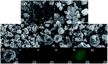 | ||
| Fig. 3 SEM images of (a) ZIF-8, (b) TiO2, (c) TiO2/ZIF-8-G1, (d) TiO2/ZIF-8-G2, (e) TiO2/ZIF-8-G3, and (f) EDS elemental mapping images of TiO2/ZIF-8-G2. | ||
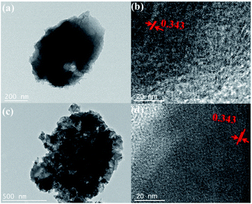 | ||
| Fig. 4 TEM images of (a) TiO2/ZIF-8-G2, (c) TiO2/ZIF-8-S2, and high-resolution transmission electron microscope (HRTEM) images of (b) TiO2/ZIF-8-G2, (d) TiO2/ZIF-8-G2. | ||
3.2 Photocatalytic activity
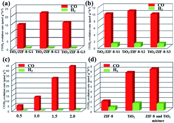
The photoreduction of CO2 has been carried out through a solid–gas reaction mode by placing TiO2, ZIF-8 and TiO2/ZIF-8 photocatalysts in a homemade reactor full of CO2 and several drops of water. This reaction mode is chosen due to its relative high product selectivity, and inhibited comparative H2 generation reaction. The detailed experimental results of various photocatalysts on the CO2 photoreduction are present and given in Fig. 6. It is obvious that CO and trace H2 have been observed for all samples. It should be mentioned that TiO2/ZIF-8-GX creates a high selectivity for CO2 photoreduction. The formation rate of CO increases from 14.63 to 21.74 μmol g−1 h−1, and then decreases to 15.9 μmol g−1 h−1 after irradiation for 2 h. Conversely, the as-synthesized TiO2 and ZIF-8 exhibited CO formation rates of 7.53 and 1.87 μmol g−1 h−1, respectively, under the same experimental conditions, revealing their much lower CO2 photoreduction efficiencies.In order to investigate the influence of the synthetic method on the photocatalytic performances, the solid synthesis method was used to prepare this type of photocatalyst. Then, the composite photocatalysts prepared via the solid synthesis method were employed to evaluate their ability for reducing CO2. These photocatalysts possess similar photocatalytic behaviours. Three samples have similar formation rates of CO after irradiation for 2 h (9.82, 10.67 and 9.80 μmol g−1 h−1 for TiO2/ZIF-8-S1, TiO2/ZIF-8-S2 and TiO2/ZIF-8-S3, respectively). Naturally, TiO2/ZIF-8-S2 exhibits the best performance. Obviously, the CO formation rates of TiO2/ZIF-8-SX are lower than those of TiO2/ZIF-8-GX. Summarily, TiO2/ZIF-8-SX exhibited inferior activities compared to the performances of TiO2/ZIF-8-GX. The different photocatalytic performances of two kinds of photocatalysts may probably result from their different structures. In order to excavate the influence of the structure on the photocatalytic performance, TiO2 from the etching of TiO2/ZIF-8-G2 and TiO2/ZIF-8-S2 was collected and employed to evaluate their photocatalytic performances. It should be mentioned that the crystallinity of TiO2 resulting from TiO2/ZIF-8-G2 is lower than that of TiO2 obtained from TiO2/ZIF-8-S2, confirmed by their PXRD patterns (Fig. S5†). The formation rates of CO are 7.50 and 5.88 μmol g−1 h−1, respectively (Fig. S6†), and TiO2 derived from TiO2/ZIF-8-G2 exhibited better photocatalytic performances than that of TiO2 from TiO2/ZIF-8-S2. The experimental results reveal that TiO2 with low crystallinity is beneficial for CO2 reduction.58 Exposed defects induced by the low crystallinity of TiO2 in TiO2/ZIF-8-GX can facilitate the separation of photogenerated electrons and holes, which favours the improvement of photocatalytic activities. ICP measurements have also been performed. The calculated results display that two types of photocatalysts possess different molar ratios of Ti to Zn, and the molar ratios of Ti to Zn in TiO2/ZIF-8-GX are higher (Tables S1 and S2†), indicating that TiO2/ZIF-8-GX could provide more reaction actives. Besides, the distribution of ZIF-8 at the surface of TiO2 in TiO2/ZIF-8-GX not only enriches CO2, but also prevents the aggregation of TiO2. In a word, the structural features of TiO2/ZIF-8-GX prefer to reduce CO2 under the irradiation of light. Conversely, the structures of TiO2/ZIF-8-SX are unfavourable to reduce CO2 because TiO2 with good crystallinity cannot suppress the separation of photogenerated electrons and holes effectively, and the photocatalytic active sites of TiO2 are difficult to form contacts with CO2 because they are trapped in the skeleton of ZIF-8.
The experimental phenomena show that the introduction of ZIF-8 indeed improves the CO2 photoreduction performances of the composite photocatalysts. The optimized performance comes from TiO2/ZIF-8-G2, and its photocatalytic production yields at the given times are 5.04, 13.38, 31.85 and 43.49 μmol g−1 (Fig. 6c). Compared to the original TiO2 and ZIF-8, as well as TiO2 derived from TiO2/ZIF-8-G2 and TiO2/ZIF-8-S2, the photocatalytic efficiency of TiO2/ZIF-8-G2 increases by two, eleven and two times, respectively. For composite photocatalysts with varied amounts of TiO2, the experimental results reveal that the photocatalytic performances improve first, and then decrease along with the increased amount of TiO2. We speculate that the increased mass ratio of TiO2 could provide more reactive sites. However, too much TiO2 hinders the CO2 absorption ability of the composite photocatalysts, suppressing the benefits of the increased active sites. The enhanced photocatalytic performance of TiO2/ZIF-8-GX is mainly due to the well-integrated structure, and could result from the following issues: (i) ZIF-8 in the composites owns a large surface area, and is favourable for capturing CO2; (ii) the distribution of ZIF-8 in the TiO2 matrix can effectively avoid the aggregation of TiO2 and make TiO2 expose more reaction active sites; (iii) the low crystallinity of TiO2/ZIF-8-GX can create more defects at the surface, which can accelerate the separation of the photogenerated electrons and holes. Naturally, the above factors make TiO2/ZIF-8-GX possess high photocatalytic activity.
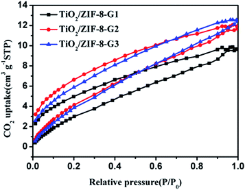
Previous achievements have demonstrated that the great CO2 adsorption capability can benefit from enhancing the photocatalytic performance.59–62 Naturally, the CO2 absorption capacities of all samples have been evaluated at room temperature. The experimental findings exhibit TiO2/ZIF-8-GX with CO2 uptakes of 9.9, 12.1 and 12.6 cm3 g−1 (Fig. 5) at 298 K, respectively. TiO2/ZIF-8-SX exhibited CO2 uptakes of 9.84, 9.87 and 11.59 cm3 g−1 (Fig. S7†) at 298 K, which are lower than those of the corresponding TiO2/ZIF-8-GX. ZIF-8 shows a CO2 uptake of 17.0 cm3 g−1,63 while TiO2 exhibits nearly no adsorption of CO2.
To demonstrate that the product actually comes from the photoreduction of CO2, the control experiments were performed. First, the homemade reactor in the absence of photocatalysts does not respond to light irradiation. Second, TiO2/ZIF-8-G2 shows no photocatalytic responses in N2 and H2O vapours. When CO2 is used to replace N2, a remarkable photocatalytic response is observed. Similar experimental findings can also be achieved for TiO2 and TiO2/ZIF-8-S2. In addition, the control experiment employing a physical mixture of TiO2 and ZIF-8 as photocatalysts exhibits lower activity than those of TiO2/ZIF-8-GX, and its formation rate of CO is 8.21 μmol g−1 h−1.
In order to highlight the excellence of our work, the previous covered photocatalysts based on MOF and semiconductors are summarized and listed in Table 1. Naturally, the reported experimental findings are used for comparison with precious experimental results.64–70 As shown in Table 1, most of the photocatalysts can only convert CO2 into CO, and the photocatalytic performance of TiO2/ZIF-8-G2 is located at a high level compared to other similar photocatalysts. This comparison implies that the structure of TiO2/ZIF-8-GX is favourable for the photocatalytic reduction of CO2.
| Photocatalyst | Product and its formation rate (μmol g−1 h−1) | Reaction agent | Light source | Ref. |
|---|---|---|---|---|
| TiO2–Co–ZIF-9 | CO 8.80, CH4 2.00, H2 2.60 | H2O vapor, 50 mg catalyst | 300 W Xe lamp | 61 |
| TiO2–Mg–CPO-27 | CO 4.09, CH4 2.35 | H2O vapor, 10 mg catalyst | 4 W LED lamp | 62 |
| CsPbBr3 QDs/UiO-66(NH2) | CO 8.21 | 10 mg | 300 W Xe lamp | 63 |
| G-CNQDs/PMOF | CO 16.10, CH4 6.86 | MeCN/TEOA (4![[thin space (1/6-em)]](https://www.rsc.org/images/entities/char_2009.gif) : :![[thin space (1/6-em)]](https://www.rsc.org/images/entities/char_2009.gif) 1) 1) |
300 W Xe lamp | 64 |
| CNNS–UiO66(Zr) | CO 9.90 | MeCN/TEOA (4![[thin space (1/6-em)]](https://www.rsc.org/images/entities/char_2009.gif) : :![[thin space (1/6-em)]](https://www.rsc.org/images/entities/char_2009.gif) 1) 1) |
300 W Xe lamp | 65 |
| CsPbBr3@ZIF-67 | CH4 29.63 | Films (mass of about 4.5 mg) | 100 W Xe lamp | 66 |
| Cu3(BTC)2@TiO2 | CH4 2.64 | CO2/H2O vapor | 300 W xenon arc lamp | 67 |
| TiO2/ZIF-8-G2 | CO 21.74 | H2O vapor, 1 mg catalyst | 40 W LED lamp | This work |
3.3 Optical and electrochemical properties
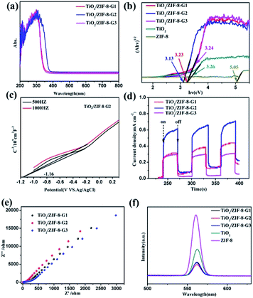
The UV-Vis diffuse reflectance spectra of ZIF-8, TiO2 and TiO2/ZIF-8-GX, as well as TiO2/ZIF-8-SX have been measured to evaluate their light absorption ability (Fig. 7a and S9†). The prepared TiO2 shows a steep absorption edge situated at about 350 nm. ZIF-8 can only adsorb UV light from 200 nm to 250 nm (Fig. S8†). TiO2/ZIF-8-G1 and TiO2/ZIF-8-G3 also show steep absorption edges around 350 nm, similar to that of TiO2. Additionally, for TiO2/ZIF-8-SX, their adsorption edges are located at about 350 nm, having similar light absorption ability. The spectra clearly reveal that TiO2/ZIF-8-G2 has a wider absorption band, compared to other photocatalysts, which indicates that it possesses a stronger light absorption capacity. TiO2/ZIF-8-G2 exhibits an expanded absorption edge at about 400 nm. The band gaps of TiO2, ZIF-8 and TiO2/ZIF-8-G1/2/3 are calculated to be 3.26 eV, 5.05 eV, 3.23 eV, 3.13 eV, 3.24 eV by the Kubelka–Munk (KM) method, respectively (Fig. 7b). With the help of the same calculation method, the band gaps of TiO2/ZIF-8-S1/2/3 are obtained to be 3.26 eV, 3.25 eV and 3.27 eV, respectively. To reveal their band structures, the Mott–Schottky (MS) measurements of TiO2, ZIF-8 and TiO2/ZIF-8-G1/2/3, as well as TiO2/ZIF-8-S1/2/3, were also carried out (Fig. 7c, S10 and S11†). With the help of the Mott–Schottky equations, the electronic band positions of TiO2/ZIF-8-GX and TiO2/ZIF-8-SX could be found. The conduction band (CB) positions of TiO2/ZIF-8-G1/2/3 and TiO2/ZIF-8-S1/2/3 were determined to be −1.08, −1.14, −1.10, −1.02, −1.07 and −1.06 eV (vs. Ag/AgCl), respectively. Their valence band (VB) positions were calculated to be 2.13, 1.97, 2.12, 2.24, 2.23 and 2.21 eV, respectively, according to the band gaps coming from the UV-Vis absorption data (Fig. 7b). Naturally, the energy band structures of TiO2 and ZIF-8 can be established based on this calculation, and is shown in Fig. S10.† Among all photocatalysts, it is clearly shown that the CB position of TiO2/ZIF-8-G2 is more negative than the reduction potential of CO2 converting into CO, which makes it easier to photoreduce CO2.The photocurrent density spectra are able to reflect the separation ability of the photo-induced charges. These data of all composite photocatalysts clearly reveal that the photocurrent density increases in the order of TiO2/ZIF-8-S3 < TiO2/ZIF-8-S1 < TiO2/ZIF-8-S2 < TiO2/ZIF-8-G3 < TiO2/ZIF-8-G1 < TiO2/ZIF-8-G2 (Fig. 7d and S9c†). Obviously, the photocurrent responses of TiO2/ZIF-8-GX are stronger than those of TiO2/ZIF-8-SX, which are consistent with their photocatalytic results. Among them, TiO2/ZIF-8-G2 possesses the maximum photocurrent density under the irradiation of light, and its high photocurrent response can be ascribed to the lower recombination rate of photogenerated electrons and holes pairs. Besides, the electrochemical impedance spectrum (EIS) is demonstrated to be a promising method for investigating the interfacial charge transfer. As shown in Fig. 7e and S9d,† the EIS plots of TiO2/ZIF-8-G2 show the smallest radius among all TiO2/ZIF-8-GX photocatalysts. Smaller resistances result in better conductivity and prefer to transfer the photogenerated electrons. It should be mentioned that the smallest radius of TiO2/ZIF-8-G2 corresponds to the result of the photocurrent measurements and CO2 photoreduction performance.
In addition, the photoluminescence (PL) emission spectra of TiO2/ZIF-8-GX, ZIF-8 and TiO2 were performed to study the ability of the photogenerated charge carrier transfer. As shown in Fig. 7f, the PL emissions of TiO2/ZIF-8-GX were quenched significantly compared to those of ZIF-8 and TiO2, revealing the inhibited photoinduced charge recombination existing in TiO2/ZIF-8-GX. This is because the defects induced by the low crystallinity of TiO2/ZIF-8-GX offer many charge transfer pathways for photogenerated electrons. Additionally, the ZIF-8 shell makes an important contribution to the transfer of photogenerated electrons due to its more positive conduction band. Both of them hinder the recombination of photoelectrons and holes, resulting in enhanced photocatalytic performances.
4. Possible photocatalytic mechanism
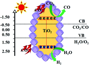
The possible CO2 photoreduction reaction pathways of TiO2/ZIF-8-GX and the corresponding possible mechanism are proposed to explain the synergistic effects between TiO2 and ZIF-8 on the photocatalytic reduction of CO2 (Fig. 8). This is because ZIF-8 possesses a large surface area, and is mainly responsible for CO2 and H2O uptake. CO2 and water molecules first enter the pores of ZIF-8, and can subsequently migrate to the surface of TiO2 through interconnected channels in the framework. Under the irradiation of light, several common intermediates (e.g., CO32−)49 are generated with the help of the chemisorption between CO2 and the surface of TiO2. TiO2 serves as the photocatalyst, and produces electrons and holes. Naturally, the photogenerated electrons gather together at the interfaces between TiO2 and ZIF-8, and then take part in the photoreduction of abundant CO2 and H2O inside ZIF-8, promoting the progress of the photocatalytic reaction (Fig. 8). Meanwhile, the adsorbed water forms contacts with the holes in TiO2, and then produces protons and OH˙.71 The appearance of this process is demonstrated by the successful detection of OH˙ (Fig. S12†). Finally, the intermediates produce the final product of CO with the help of the generated electrons and protons.5. Conclusions
In summary, various binary semiconductor/ZIF photocatalysts (TiO2/ZIF-8) have been fabricated with the help of the grinding method and the solid synthesis method. The photocatalysts prepared by the grinding method exhibit better photocatalytic performances than those of the photocatalysts fabricated by the solid synthesis method. The experimental finding demonstrates that different synthetic methods result in varied photocatalytic performances, caused by their different structural features. The resulting TiO2/ZIF-8-GX exhibits enhanced photocatalytic reduction efficiencies toward CO2 compared to pure TiO2 and ZIF-8, as well as TiO2/ZIF-8-SX, and TiO2/ZIF-8-G2 exhibits the highest CO formation rate of 21.74 μmol g−1 h−1. The good performance could be attributed to the enhanced CO2 absorption ability and the well-integrated structure, which can expose more active sites and absorb more CO2. This work may offer some guidance for designing composited photocatalysts with high efficiency.Conflicts of interest
There are no conflicts to declare.Acknowledgements
The authors are grateful for the financial aid from the National Natural Science Foundation of China (No. 21601109).References
- Z. Sun, N. Talreja, H. Tao, J. Texter, M. Muhler, J. Strunk and J. Chen, Angew. Chem., Int. Ed., 2018, 57, 760 CrossRef PubMed.
- J. L. White, M. F. Baruch, J. E. Pander, Y. Hu, I. C. Fortmeyer, J. E. Park, T. Zhang, K. Liao, J. Gu, Y. Yan, T. W. Shaw, E. Abelev and A. B. Bocarsly, Chem. Rev., 2015, 115, 12888 CrossRef CAS PubMed.
- L. J. Wang, R. l. Wang, X. Zhang, J. l. Mu, Z. Y. Zhou and Z. M. Su, ChemSusChem, 2020, 13, 2973 CrossRef CAS PubMed.
- H. Huang, J. Lin, G. Zhu, Y. Weng, X. Wang, X. Fu and J. Long, Angew. Chem., Int. Ed., 2016, 55, 8314 CrossRef CAS PubMed.
- W. Kim, E. Edri and H. Frei, Acc. Chem. Res., 2016, 49, 1634 CrossRef CAS PubMed.
- X. Liu, S. Inagaki and J. Gong, Angew. Chem., Int. Ed., 2016, 55, 14924 CrossRef CAS PubMed.
- X. Liu, J. Iocozzia, Y. Wang, X. Cui, Y. Chen, S. Zhao, Z. Li and Z. Lin, Energy Environ. Sci., 2017, 10, 402 RSC.
- M. Lu, J. Liu, Q. Li, M. Zhang, M. Liu, J. L. Wang, D. Q. Yuan and Y. Q. Lan, Angew. Chem., Int. Ed., 2019, 58, 12392 CrossRef CAS PubMed.
- M. Lu, Q. Li, J. Liu, F. M. Zhang, L. Zhang, J. L. Wang, Z. H. Kang and Y. Q. Lan, Appl. Catal., B, 2019, 254, 624 CrossRef CAS.
- H. Zhang, J. Wei, J. Dong, G. Liu, L. Shi, P. An, G. Zhao, J. Kong, X. Wang, X. Meng, J. Zhang and J. Ye, Angew. Chem., Int. Ed., 2016, 55, 14310 CrossRef CAS PubMed.
- M. Zhang, M. Lu, Z. L. Lang, J. Liu, M. Liu, J. N. Chang, L. Y. Li, L. J. Shang, M. Wang, S. L. Li and Y.-Q. Lan, Angew. Chem., Int. Ed., 2020, 59, 2 CrossRef.
- Y. H. Luo, L. Z. Dong, J. Liu, S. L. Li, Y. Q. Lan, W. G. Tu, Y. Zhou and Z. G. Zou, Coord. Chem. Rev., 2019, 390, 86 CrossRef CAS.
- K. Li, B. Peng and T. Peng, ACS Catal., 2016, 6, 7485 CrossRef CAS.
- C. l. Wang, Z. X. Sun, Y. Zheng and Y. H. Hu, J. Mater. Chem. A, 2019, 7, 865 RSC.
- L. F. Wei, C. L. Yu, Q. H. Zhang, H. Liu and Y. Wang, J. Mater. Chem. A, 2018, 6, 22411 RSC.
- M. Marszewski, S. W. Cao, J. G. Yu and M. Jaroniec, Mater. Horiz., 2015, 2, 261 RSC.
- G. Sneddon, A. Greenaway and H. H. P. Yiu, Adv. Energy Mater., 2014, 4, 1301873 CrossRef.
- M. Lu, Q. Li, J. Liu, F. M. Zhang, L. Zhang, J. L. Wang, Z. H. Kang and Y. Q. Lan, Appl. Catal., B, 2019, 254, 624 CrossRef CAS.
- Y. Ma, X. Wang, Y. Jia, X. Chen and H. L. Han, Chem. Rev., 2014, 114, 9987 CrossRef CAS PubMed.
- D. Chen, X. G. Zhang and A. F. J. Lee, J. Mater. Chem. A, 2015, 3, 14487 RSC.
- S. W. Cao, J. X. Low, J. G. Yu and M. Jaroniec, Adv. Mater., 2015, 27, 2150 CrossRef CAS PubMed.
- S. N. Habisreutinger, L. Schmidt-Mende and J. K. Stolarczyk, Angew. Chem., Int. Ed., 2013, 52, 7372 CrossRef CAS PubMed.
- Y. P. Yuan, L. W. Ruan, J. Barber, S. C. J. Loo and C. Xue, Energy Environ. Sci., 2014, 7, 3934 RSC.
- N. Linares, A. M. Silvestre-Albero, E. Serrano, J. Silvestre-Albero and J. García-Martínez, Chem. Soc. Rev., 2014, 43, 7681 RSC.
- H. Q. Sun and S. B. Wang, Energy Fuels, 2014, 28, 22 CrossRef CAS.
- Q. J. Xiang, B. Cheng and J. G. Yu, Angew. Chem., Int. Ed., 2015, 54, 11350 CrossRef CAS PubMed.
- T. Zhang and W. B. Lin, Chem. Soc. Rev., 2014, 43, 5982 RSC.
- S. Kumar, M. Y. Wani, C. T. Arranja, J. A. Silva, B. Avula and A. J. Sobral, J. Mater. Chem. A, 2015, 3, 19615 RSC.
- J. Y. Wang, B. S. Liu and K. Nakata, Chin. J. Catal., 2019, 40, 403 CrossRef CAS.
- C. Z. Wen, Q. H. Hu, Y. N. Guo, X. Q. Gong, S. Z. Qiao and H. G. Yang, Chem. Commun., 2011, 47, 6138 RSC.
- P. Zhou, J. G. Yu and M. Jaroniec, Adv. Mater., 2014, 26, 4920 CrossRef CAS PubMed.
- M. Yaghi, H. L. Li, C. Davis, D. Richardson and T. L. Groy, Acc. Chem. Res., 1998, 31, 474 CrossRef.
- B. Moulton and M. J. Zaworotko, Chem. Rev., 2001, 101, 1629 CrossRef CAS PubMed.
- X. Meng, H. N. Wang, S. Y. Song and H. J. Zhang, Chem. Soc. Rev., 2017, 46, 464 RSC.
- H. N. Wang, X. Meng, L. Z. Dong, Y. Chen, S. L. Li and Y. Q. Lan, J. Mater. Chem. A, 2019, 7, 24059 RSC.
- X. Meng, Y. H. Zou, Y. Y. Zhang and L. S. Wang, Journal of Liaocheng University, 2019, 32, 90 Search PubMed.
- S. M. J. Rogge, A. Bavykina, J. Hajek, H. Garcia, A. I. Olivos-Suarez, A. Sepúlveda-Escribano, A. Vimont, G. Clet, P. Bazin, F. Kapteijn, M. Daturi, E. V. Ramos-Fernandez, F. X. L. Xamena, V. V. Speybroeck and J. Gascon, Chem. Soc. Rev., 2017, 46, 3134 RSC.
- W. P. Lustig, W. S. Mukherjee, N. D. Rudd, A. V. Desai, J. Li and S. K. Ghosh, Chem. Soc. Rev., 2017, 46, 3242 RSC.
- K. Fujie and H. Kitagawa, Coord. Chem. Rev., 2016, 370, 382 CrossRef.
- X. Meng, H. N. Wang, X. K. Wang, L. Z. Dong and Y. H. Zou, New J. Chem., 2019, 43, 24 RSC.
- X. Meng, H. N. Wang, Y. H. Zou, L. S. Wang and Z. Y. Zhou, Dalton Trans., 2019, 48, 10422 RSC.
- H. N. Wang, M. Zhang, A. M. Zhang, F. C Shen, X. K. Wang, S. N. Sun, Y. J. Chen and Y. Q. Lan, ACS Appl. Mater. Interfaces, 2018, 10, 32265 CrossRef CAS PubMed.
- X. Meng, H. N. Wang, L. S. Wang, Y. H. Zou and Z. Y. Zhou, CrystEngComm, 2019, 21, 3146 RSC.
- C. Wang, Z. G. Xie, K. E. deKrafft and W. L. Lin, J. Am. Chem. Soc., 2011, 133, 13445 CrossRef CAS PubMed.
- Y. H. Fu, D. R. Sun, Y. J. Chen, R. K. Huang, Z. X. Ding, X. Z. Fu and Z. H. Li, Angew. Chem., Int. Ed., 2012, 51, 3364 CrossRef CAS PubMed.
- H. Q. Xu, J. H. Hu, D. K. Wang, Z. H. Li, Q. Zhang, Y. Luo, S. H. Yu and H. L. Jiang, J. Am. Chem. Soc., 2015, 137, 13440 CrossRef CAS PubMed.
- Q. Liu, Z. X. Low, L. X. Li, A. Razmjou, K. Wang, J. F. Yao and H. T. Wang, J. Mater. Chem. A, 2013, 1, 11563 RSC.
- S. B. Wang and X. C. Wang, Appl. Catal., B, 2015, 162, 494 CrossRef CAS.
- X. He, Z. R. Gan, S. Fisenko, D. W. Wang, H. M. El-Kaderi and W. N. Wang, ACS Appl. Mater. Interfaces, 2017, 9, 9688 CrossRef CAS PubMed.
- L. Z. Zhai, Y. H. Qian, Y. X. Wang, Y. D. Cheng, J. Q. Dong, S. B. Peh and D. Zhao, ACS Appl. Mater. Interfaces, 2018, 10, 36933 CrossRef CAS PubMed.
- R. Li, J. H. Hu, M. S. Deng, H. L. Wang, X. J. Wang, Y. L. Hu, H. L. Jiang, J. Jiang, Q. Zhang, Y. Xie and Y. J. Xiong, Adv. Mater., 2014, 26, 4783 CrossRef CAS PubMed.
- W. L. Zhong, C. Li, X. M. Liu, X. K. Bai, G. S. Zhang and C. X. Lei, Microporous Mesoporous Mater., 2020, 306, 110401 CrossRef CAS.
- X. Zeng, L. Q. Huang, C. N. Wang, J. S. Wang, J. T. Li and X. T. Luo, ACS Appl. Mater. Interfaces, 2016, 8, 20274 CrossRef CAS PubMed.
- Y. J. Ma, Q. Tang, W. Y. Sun, Z. Y. Yao, W. H. Zhu, T. Li and J. Y. Wang, Appl. Catal., B, 2020, 270, 118856 CrossRef CAS.
- M. Zhang, Q. G. Shang, Y. Q. Wan, Q. R. Cheng, G. Y. Liao and Z. Q. Pan, Appl. Catal., B, 2019, 241, 149 CrossRef CAS.
- Y. Zhang, W. Q. Cui, W. J. An, L. Liu, Y. H. Liang and Y. F. Zhu, Appl. Catal., B, 2018, 221, 36 CrossRef CAS.
- R. Li, W. Li, C. Jin, Q. Y. He and Y. Z. Wang, J. Alloys Compd., 2020, 825, 154008 CrossRef CAS.
- Q. Chen, S. J. Wu, S. X. Zhong, B. J. Gao, W. J. Wang, W. H. Mo, H. J. Lin, X. X. Wei, S. Bai and J. R. Chen, J. Mater. Chem. A, 2020, 8, 21208 RSC.
- S. Wang, M. Xu, T. Peng, C. Zhang, T. Li, I. Hussain, J. Wang and B. Tan, Nat. Commun., 2019, 10, 676 CrossRef CAS PubMed.
- D. Wang, R. Huang, W. Liu, D. Sun and Z. Li, ACS Catal., 2014, 4, 4254 CrossRef CAS.
- R. Li, W. Zhang and K. Zhou, Adv. Mater., 2018, 30, 1705512 CrossRef PubMed.
- M. Lu, Q. Li, J. Liu, F. M. Zhang, L. Zhang, J. L. Wang, Z. H. Kang and Y. Q. Lan, Appl. Catal., B, 2019, 254, 624 CrossRef CAS.
- Y. Liu, L. Deng, J. P. Sheng, F. Y. Tang, K. Zeng, L. Q. Wang, K. X. Liang, H. Hu and Y. N. Liu, Appl. Surf. Sci., 2019, 498, 143899 CrossRef CAS.
- J. Wang, C. Xue, W. Q. Yao, J. Liu, X. X. Gao, R. L. Zong, Z. Yang, W. J. Jin and D. P. Tao, Appl. Catal., B, 2019, 250, 369 CrossRef CAS.
- S. Yan, S. Q. Yang, H. Xu, M. Zhao, X. Zhang and J. Ye, J. Mater. Chem. A, 2016, 4, 15126 RSC.
- S. Wan, M. Ou, Q. Zhong and X. Wang, Chem. Eng. J., 2019, 358, 1287 CrossRef CAS.
- C. Zheng, X. Y. Qiu, J. Y. Han, Y. F. Wu and S. Q. Liu, ACS Appl. Mater. Interfaces, 2019, 11, 42243 CrossRef CAS PubMed.
- N. Sadeghi, S. Sharifnia and M. Sheikh Arabi, J. CO2 Util., 2016, 16, 450 CrossRef CAS.
- Z. C. Kong, J. F. Liao, Y. J. Dong, Y. F. Xu, H. Y. Chen, D. B. Kuang and C. Y. Su, ACS Energy Lett., 2018, 3, 2656 CrossRef CAS.
- R. Li, J. Hu, M. Deng, H. Wang, X. Wang, Y. Hu, H. L. Jiang, J. Jiang, Q. Zhang, Y. Xie and Y. Xiong, Adv. Mater., 2014, 26, 4783 CrossRef CAS PubMed.
- H. N. Wang, H. Chen, L. L. Chen, W. H. Zhang, Z. Y. Zhou and X. Meng, Res. Chem. Intermed., 2018, 44, 1261 CrossRef CAS.
Footnotes |
| † Electronic supplementary information (ESI) available: FTIR spectra of photocatalysts, PXRD patterns of photocatalysts, SEM images, time–yield plots of CO and H2 over TiO2/ZIF-8-G2, UV-Vis diffuse reflectance spectra, PL spectra, Mott–Schottky plots. See DOI: 10.1039/d0na00814a |
| ‡ Yan-Hong Zou and Hai-Ning Wang made equal contributions to this paper. |
| This journal is © The Royal Society of Chemistry 2021 |

