 Open Access Article
Creative Commons Attribution 3.0 Unported Licence
A new approach to near-surface positron annihilation analysis of ion irradiated ferritic alloys
Vladimír
Kršjak
 ac,
Petr
Hruška
b,
Jarmila
Degmová
 *ac,
Stanislav
Sojak
ac,
Pavol
Noga
c,
Tielong
Shen
d,
Veronika
Sabelová
a,
Werner
Egger
e and
Vladimír
Slugeň
a
aSlovak University of Technology in Bratislava, Faculty of Electrical Engineering and Information Technology, Institute of Nuclear and Physical Engineering, Ilkovicova 3, Bratislava 81219, Slovakia. E-mail: jarmila.degmova@stuba.sk
bCharles University, Faculty of Mathematics and Physics, V Holesovickach 2, Prague 18000, Czech Republic
cSlovak University of Technology in Bratislava, Faculty of Materials Science and Technology in Trnava, Advanced Technologies Research Institute, Jana Bottu 2781/25, Trnava 91724, Slovakia
dChinese Academy of Sciences, Institute of Modern Physics, Lanzhou, Gansu 730000, China
eUniversität der Bundeswehr München, Institut für Angewandte Physik und Messtechnik, Werner-Heisenberg-Weg 39, D-85577 Neubiberg, Germany
First published on 3rd September 2021
Abstract
The present work provides an innovative approach to the near-surface slow-positron-beam (SPB) study of structural materials exposed to ion-beam irradiation. This approach enables the use of variable-energy positron annihilation lifetime spectroscopy (PALS) to characterise a wide range of microstructural damage along the ion implantation profile. In a typical application of the SPB PALS technique, positron lifetime is used to provide qualitative information on the size of vacancy clusters as a function of the positron energy, i.e., the probing depth of the spectrometer. This approach is limited to a certain defect concentration above which the positron lifetime gets saturated. In our experiments, we investigated the back-diffusion of positrons and their annihilation at the surface. The probability of such an event is characterised by the positron diffusion length, and it depends on the density of lattice defects, even in the saturation range of the positron lifetime. Until now, the back-diffusion experiments were reported only in connection with Doppler broadening spectroscopy (DBS) of positron-annihilation radiation. To verify the validity of the used approach, we compared the obtained results on helium-implanted Fe9Cr alloy and its oxide dispersion strengthened variant with the transmission electron microscopy and “conventional” slow positron DBS analysis.
1. Introduction
Irradiation of bulk specimens in neutron radiation environments of various nuclear reactors inevitably leads to an induced activity of the tested samples. To minimise the handling of “hot” radioactive materials, research studies are either aimed at small-scale (miniaturised) samples1 or relatively low neutron fluencies.2,3 To experimentally simulate the neutron environment without the induced activity, neutrons can be effectively replaced in irradiation experiments by charged particles such as protons,4 alphas5 or self-ions,6 respectively. A standalone ion implantation experiment, or irradiations using a combination of two,7 or three8 different ions simultaneously, enables very efficient simulation of the environments of thermonuclear reactors, with high production rates of transmutation elements such as hydrogen or helium. However, high displacement damage rates of ion implantation in a narrow near-surface region limit the scientific value of ion implantation studies. The non-uniform damage profile requires investigation by depth-sensitive methods, enabling the probe of different regions within the Bragg curve. Typical experimental tools suitable for such studies are a quasi-non-destructive focused ion beam (FIB) lift-out technique followed by transmission electron microscopy (TEM) characterisation or a non-destructive slow positron beam (SPB) technique of positron annihilation spectroscopy (PAS).Numerous studies have been published in the last two decades on SPB studies of ion-implanted samples.9–12 The experiments were focusing either on positron annihilation lifetime spectroscopy (PALS)9 or on measurements of the momentum distribution of electrons in a material10–12 using Doppler broadening spectroscopy (DBS) of the annihilation line. Particular attention was paid to study the helium behaviour in Fe-based materials due to its importance in nuclear fusion related research. PAS has proven to be an excellent tool for the characterisation of lattice imperfections in acting as sinks for radiation-induced defects and transmutation helium.13,14 The role of oxide precipitates in the radiation resistance of ferritic/martensitic steels has been investigated by both commonly used PAS techniques, PALS and DBS. There are, however, certain limitations of the applicability of PAS, particularly the positron lifetime technique used in the studies of materials with a high concentration of nano-features such as oxide-dispersion strengthened steels (ODS). The positron trapping in these materials is often saturated, i.e., all positrons are trapped at defects and further introduction of defects (e.g., by irradiation) does not lead to a clear response in positron lifetime spectra. However, positron back-diffusion measurements using slow (monoenergetic) positron beams have a higher sensitivity limit.14 Positrons implanted in the near-surface region of the studied sample have a certain probability of diffusing back and annihilating at the surface. Such annihilation can be clearly distinguished from the annihilation in the material bulk, and the probability of such an event depends on the density of lattice defects, even in the saturation range of the positron lifetime technique. The probability of the back diffusion to the surface is characterised by the positron diffusion length.15
The investigation of positron diffusion in ion-irradiated Fe-based alloys has been previously published in a few research studies.9,16 The experimental values of the positron diffusion length are commonly obtained using one-dimensional Doppler broadening spectra, which were collected as a function of the positron energy. To obtain a sufficient number of counts in the spectra in reasonable acquisition time, typically either a strong radioisotope positron source with a giga-Becquerel activity is required, or, alternatively, one can use large-scale facilities utilising intense gamma sources (either bremsstrahlung emitted from decelerating electrons or gamma released from nuclear reactions), producing electron–positron pairs. While the DBS technique is suitable for SPB studies and provides chemical information from the vicinity of the annihilation site, it does not provide qualitative information on the size of vacancy clusters, for instance. From this point of view, the positron lifetime technique is superior to the DBS technique. Nevertheless, a slow positron lifetime spectrometer requires precise timing of the pulses and much higher positron flux. This limits the choice of suitable positron sources to large-scale facilities utilising pair production by intense gamma sources.
The pulsed low energy positron system (PLEPS)17 installed at the high-intensity positron source NEPOMUC18 is one of few and the first facility of its kind, enabling precise positron lifetime measurements with variable-energy positron beam. This paper demonstrates the feasibility of using the lifetime spectra obtained at PLEPS or any other pulsed low-energy positron beam to determine positron diffusion length. The obtained results are compared to previous DBS measurements on the same helium-implanted materials.16 The present study complements and concludes decade-long research aimed at applying PAS techniques to improve the fundamental understanding of radiation tolerance of nano-oxide dispersion-strengthened steels.
2. Materials and methods
The present study was conducted on two Fe9Cr steels, namely Eurofer 97 and the ODS variant of this steel. The nominal chemical composition of Eurofer 97, as well as basic material characteristics, can be found in ref. 19. The ODS variant was prepared by mechanical alloying of the base steel powder prepared by inert gas atomisation with 0.3 wt% yttrium oxide powder.202.1 Ion implantations
Samples were prepared by electrical discharge cutting and mechanical polishing, followed by electrochemical polishing in a solution of perchloric acid and acetic acid. To ensure the removal of the plastic deformation of the surface layer, introduced during the mechanical polishing process, >15 μm of the sample surface was electropolished out. Two samples of both investigated materials were implanted by 500 keV He+ ions with a fluence 1022 m−2 using the ion implanter at ATRI MTF STU.21 Irradiation temperature was kept near room temperature. The number of displacements per atom (dpa), calculated according to the NRT model22 and averaged over a 1.6 μm region, was 6.5, with a peak value of 29.5. According to SRIM23 simulation, the dpa peak was obtained in a depth of 950 nm, while the helium ion peak concentration was obtained in 1000 nm depth (Fig. 1).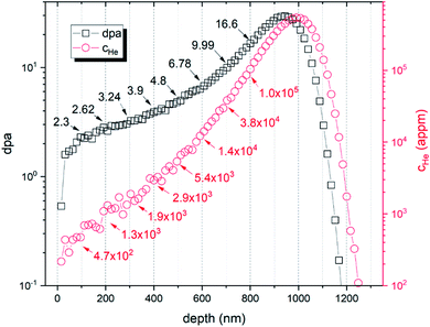 | ||
| Fig. 1 SRIM simulation of the ion implantation experiment showing displacement damage (dpa) and helium concentration (cHe). | ||
2.2 Slow positron beam experiments
Two implanted samples, together with the reference samples, were investigated at the PLEPS facility.17 The investigation was performed within one week after the He+ implantations. During this period of time, the samples were kept in a dry sealed plastic container in order to minimise surface oxidation. Positron annihilation lifetime spectroscopy (PALS) measurements were performed using positron beam energies in the range of 0.5–18 keV. Given the density of the studied Fe9Cr alloys [7.9 g cm−3], this energy range approximately corresponds to a mean positron implantation depth in the range of 2–520 nm. The choice of the implantation peak being placed beyond the positron stopping maximum was due to our desire to focus on engineering-relevant irradiation conditions in terms of helium production rates. For each positron energy, at least 4 × 10⁶ annihilation events were collected, and the lifetime spectra were analysed in the LT10 program24 using a standard trapping model19 and a three-component decomposition. Unlike conventional lifetime spectra obtained using encapsulated radioisotope sources, the so-called source component, describing the positron annihilation in the source and its encapsulation, was not considered during the fitting.The obtained positron lifetime results were compared to our earlier study of these materials using Doppler broadening spectroscopy (DBS). The DBS experiments, performed at the Aalto university's DBS facility, were reported in details in ref. 16 and 25. Although the DBS results were obtained for positron energies ranging between 0.5–36 keV, in this work, we use reference data for the same energy range that was used for PALS. It is important to note that the samples characterised by DBS were not electrochemically polished, and the surface was prepared only by mechanical polishing with silicon carbide paper followed by diamond paste with a final grade of 1 μm. This was considered in the analysis of the experimental data and the comparison with the PALS results.
The fundamental advantage of slow positron beam data lies in a depth-sensitive representation of the microstructure, which is enabled by the variable energy of the used positron probes. The mean implantation depth of positrons, z [nm] can be easily estimated for most metals using the incident positron energy E [keV] and the target materials density ρ [g cm−3] according to eqn (1).26
 | (1) |
In the case of the inhomogeneous depth distribution of microstructural defects, it is important to consider the whole stopping profile of monoenergetic positrons described by the Makhovian distribution.27 As illustrated in Fig. 2, this distribution broadens with increasing positron energy. While at low energies, the stopping profile is localised in a relatively narrow region (tens of nm to few hundreds of nm), higher energy positrons (≥12 keV) are distributed over a relatively wide region (several hundreds of nm). This needs to be considered in the interpretation of data obtained on ion-implanted specimens, also addressed in this study, whose depth distribution of radiation-induced defects follows the Bragg curve. More details on this issue can be found, for instance, in10.
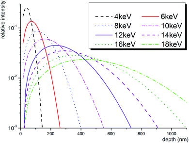 | ||
| Fig. 2 Theoretical positron stopping profiles in Fe-based alloy calculated using Makhovian distribution.27 | ||
The introduction of new vacancy-type defects in solids can be characterised by positron annihilation spectroscopy either in terms of an introduction of a new defect component(s) in positron lifetime spectrum (PALS measurements) or in terms of an increase of the line shape S parameter (DBS measurements).2 Positron lifetime is given by an overlap of the positron density and the local electron density at the annihilation site. S parameter characterises the Doppler broadening of the annihilation line due to the non-zero momentum of the annihilating electrons. Both quantities, therefore, carry information about the annihilation site, i.e., local electron density and local electron momentum distribution, respectively. The average increase of positron lifetime or the increase of S parameter usually indicates enhanced trapping at defects in the studied material. In irradiation experiments with high production rates of helium, there appears, however, a competitive process to the increase of positron trapping. The reason is a fast migration of interstitial helium into vacancies, resulting in a decrease of both positron trapping and positron localisation at vacancy-type defects.
In a perfect lattice, all positrons annihilate in the free delocalised state. The introduction of defects into the perfect lattice leads to a localisation of positrons at these defects (introduction of new positron lifetime component) and a reduction of the free positron lifetime, as described by the simple trapping model, eqn (2).19
 | (2) |
When more than one type of defect is present in the material, it is reasonable to consider the evaluation of the mean positron lifetime (τmean), rather than the lifetimes and intensities of the individual components of the spectra. τmean is defined as a weighted average of positron lifetime components. According to the simple trapping model, with increasing concentration of defects, the positron trapping at defects is enhanced, the effective lifetime τeff is reduced by the trapping rate, while the mean positron lifetime τmean increases.
It is important to note that the trapping rate is proportional to the density of traps only in so-called transition-limited positron trapping, which assumes a small size of positron traps with a spatial extent much less than the positron de Broglie (thermal) wavelength (∼few nm).19 In such case of homogeneously distributed small defects, the positron diffusion constant D+ is not a function of space coordinates, and the effective positron lifetime τeff is proportional to the effective positron diffusion length in the given material (eqn (3)).
 | (3) |
Using the above two equations, one can express the positron trapping rate at defects [s−1] via positron diffusion length as follows:
 | (4) |
As mentioned above, the mean positron lifetime (measured by PALS) and the S parameter (measured by DBS) carry information about the local electronic structure at the annihilation site. The total S parameter can be, similarly to the eqn (2), expressed as a superposition of (generally unknown) partial S parameters,† corresponding to the annihilation of free positrons and positrons trapped at defects, respectively. Despite this analogy, the positron lifetime depth profiles were, to our knowledge, never reported to be used in data treatment using VEPFIT code. To justify and support this procedure and compare the results of the slow positron beam measurements using PALS and DBS techniques, we need to describe the behaviour of positrons near the interface of two layers, which are characterised by different S parameters and mean positron lifetimes. For each positron energy, the distribution of depths, where positrons annihilate, is broadened by implantation profile, described by Makhovian distribution, and following diffusion of thermalised positrons, characterised by the effective positron diffusion length. As a result, the experimentally obtained mean lifetime and S parameter values are given by the superposition of mean lifetimes τmean,1 and τmean,2, and S parameters S1 and S2, respectively.
| τmean = n1τmean,1 + n2τmean,2 | (5) |
| S = n1S1 + n2S2 | (6) |
Fractions n1 and n2 of positron annihilation in layer 1 or layer 2, respectively, are the same for the mean positron lifetime as well as for the S parameter. Therefore, both parameters follow the same phenomenon, which is comprehended by the VEPFIT program very well. In this case, applying the VEPFIT analysis, usually used for the analysis of S(E) curves obtained by DBS, to the analysis of τmean(E) measured at PLEPS is justified. There is, nevertheless, a limit in the applicability of the presented approach. Unlike the S-parameter and defect positron lifetime components, which are inherent to a given layer in a multilayer system, the free-positron lifetime component and therefore the positron mean-lifetime are not inherent to a single layer and depend also on the properties (e.g., defect concentrations) of adjacent layers. This means that eqn (5). can be used as long as the contribution of free positrons to positron mean-lifetime is insignificant as in the case of saturated trapping. Although this seems to be a strong condition, one must keep in mind that all PALS experiments on realistic structural materials, such as steels, exposed to harsh radiation conditions essentially lead to a saturated or a near-saturated positron trapping.
2.3 TEM characterisation
The cross-sectional TEM samples of the irradiated steels were prepared using the focused ion beam (FIB) lift-out techniques in the FEI Helios Nanolab system, with a Ga acceleration voltage in the range from 1 kV to 30 kV. In the next step, a cleaning process to remove the FIB damaged layer was performed by low energy (Ga) ion milling. Microstructural characterisation was performed using FEI Tecnai F20 TEM, with an accelerating voltage of 200 kV. TEM thin foils, mounted on a double-tilt stage, were tilted away from the zone axis for emphasising the bubble contrast. The thickness of each lamella was obtained by TEM and varied between 65 and 75 nm. Under-focused bright-field images were performed for characterising He bubble distributions. In this work, bright-field TEM images were taken at an exposure time of 2 s by a CCD camera with 4008 × 2672 pixels.3. Results and discussion
To complement and verify the proposed methodology based on slow positron beam experiments, cross-sectional TEM observations have been performed. The obtained TEM data provided the initial guess values of the layer boundaries as well as the qualitative characterisation of helium bubbles in the range of irradiation conditions, where the helium production is in the same order of magnitude as the concentrations expected in the spallation neutron target.3.1 TEM characterisation
The cross-sectional TEM observation enabled to identify the region with fully grown helium bubbles and to provide a qualitative analysis in terms of their size distribution. For both materials, TEM-resolvable (>1 nm) He bubbles were observed in the region of >300 nm below the surface, which corresponds to displacement damage of >2.5 dpa and helium concentration (cHe) of >1000 appm. Due to limited spatial resolution, TEM analysis did not indicate any major enhancement of radiation resistance for ODS steel in these “low” irradiation conditions. A detailed TEM analysis was performed in the region with substantially higher helium concentration. Fig. 3 shows a cross-sectional TEM image of the two studied materials, with magnified insets corresponding to 450–580 nm, i.e., 3600–10![[thin space (1/6-em)]](https://www.rsc.org/images/entities/char_2009.gif) 800 appm He, or 4.0–5.9 dpa, respectively. The obtained size distribution of helium bubbles is shown in the histogram in Fig. 4.
800 appm He, or 4.0–5.9 dpa, respectively. The obtained size distribution of helium bubbles is shown in the histogram in Fig. 4.
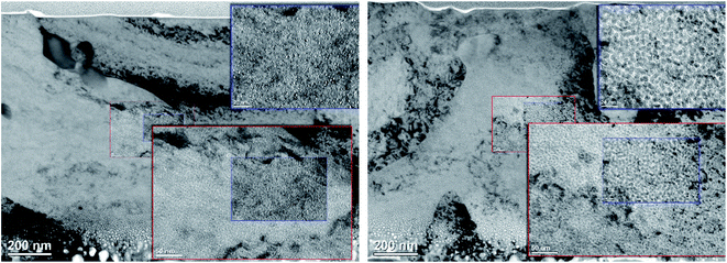 | ||
| Fig. 3 Cross-sectional TEM image of the investigated Fe9Cr alloy (left) and its ODS variant (right). The upper right insets correspond to a region 450–580 nm below the surface. | ||
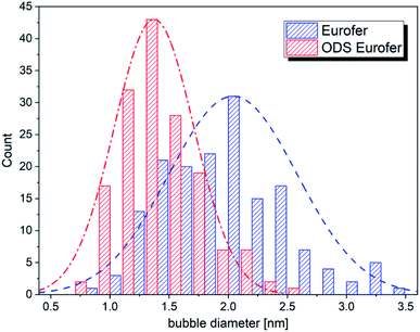 | ||
| Fig. 4 The size distribution of helium bubbles in the studied materials, corresponding to the magnified insets in Fig. 3. | ||
As can be seen in Fig. 4, the average size of helium bubbles is significantly lower (<1.5 nm) in the ODS alloy in comparison to non-ODS alloy (∼2 nm). With increasing depth and with approaching displacement damage and helium concentration peaks, the size of bubbles grows significantly (well above 5 nm), but without an obvious difference between the two studied materials. The possible reason for the similarity in the microstructural evolution is the increasing dominance of bubbles in the sinking of new vacancies and helium atoms,30 as well as in the coalescence of the bubbles.5
3.2 PAS characterisation
The present study, which proposes a new approach to obtain the effective positron diffusion length, builds on the well-known correlation between the mean positron lifetime obtained from PALS measurements and the line-shape S parameter obtained from DBS characterisation. The often nearly linear correlation between these two complementary PAS parameters has been reported in numerous papers in the past, including our study on helium embrittlement of f/m steels.32–34
The application of slow positron beam techniques, or depth-sensitive analytical techniques in general, on the characterisation experiments of ion-implanted samples is naturally facing the problem with the nonuniform damage profile. In the case of positron annihilation spectroscopy, the eventual need for a shift from transition-limited to diffusion-limited trapping may lead to some unexpected outcomes. In the first case, diffusion coefficient D+ is a constant and the effective positron lifetime is bound with diffusion length by eqn (3). As described above, increasing mean lifetime suggests enhanced trapping at defects, caused either by an increased concentration or increased size of defects. At the same time, the effective lifetime decreases due to enhanced trapping, and, according to eqn (3), the diffusion length decreases as well. In the second case (diffusion-limited trapping), the positron density becomes a function of spatial co-ordinates, since positron density is depleted in the vicinity of defects. In contrast, in the case of transition-limited trapping, positron density is independent on spatial co-ordinates (it depends on time only). For a constant D+, a positron diffuses on average for a time τf until it either annihilates as a free positron or is trapped in a defect. The trapping probability is given by the trapping rate κ, only.
Let us consider two hypothetical scenarios of structural materials, such as steel, exposed to a harsh radiation environment. In the first scenario, the irradiation experiment leads to a homogeneity in microstructure, which contains a high density of relatively shallow traps (“small” helium-filled vacancy clusters). In the second one, the irradiated microstructure is inhomogeneous and contains a lower density of deep positron traps such as “large” voids or bubbles. Comparing to the unirradiated material, the mean lifetime of positrons, as well as the positron trapping rate, will likely be higher in the irradiated materials in both scenarios. The effective positron diffusion length L+,eff, on the other hand, does not have to follow the same trend in the two scenarios. In the first scenario, L+,eff decreases with the increase of positron trapping, i.e., with the mean positron lifetime. A plausible outcome of the second scenario is that all three parameters, i.e., mean positron lifetime, positron trapping rate and the effective diffusion length, will increase.
| E [keV] | Depth [nm] | τ 1 [ps] | I 1 [%] | τ 2 [ps] | I 2 [%] | τ 3 [ps] | τ AVG [ps] | Fit's variance |
|---|---|---|---|---|---|---|---|---|
| Fe9Cr | ||||||||
| 4 | 50 | 54 | 38.3 | 230 | 41.0 | 446 | 207.0 | 1.06 |
| 18 | 500 | 35 | 12.9 | 158 | 84.0 | 520 | 153.3 | 1.02 |
![[thin space (1/6-em)]](https://www.rsc.org/images/entities/char_2009.gif) |
||||||||
| ODS Fe9Cr | ||||||||
| 4 | 50 | 42 | 26.0 | 220 | 59.0 | 450 | 208.4 | 1.07 |
| 18 | 500 | 33 | 19.1 | 215 | 78.0 | 550 | 189.6 | 1.12 |
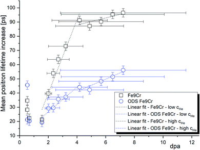
In our recent work,16 we reported slow positron DBS characterisation of the same materials and implantation conditions. Fig. 5 shows the increase of the positron mean lifetime (τMLT) after the implantation as a function of the S parameter increase in terms of absolute values. The reference values considered are the S-parameter and τMLT obtained for the un-implanted samples of the studied materials using the same positron beam energy. One can see a nearly linear dependence of the two parameters. A similar observation was reported in our previous work on f/m steels irradiated in a spallation neutron target with relatively high He production rates.33 This behaviour supports the assumption that the positron diffusion equation can be used to describe the microstructural damage in the same manner for both techniques utilising slow positrons. In other words, it justifies the analysis of the positron lifetime depth profiles using the VEPFIT software, which was, to our best knowledge, not reported in the literature until now. The slightly different slopes of the two data sets in Fig. 5 are due to different trapping rates of positrons in the two studied materials.
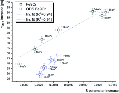 | ||
| Fig. 5 The positron mean lifetime (τMLT) as a function of the S parameter in helium-implanted f/m steel for various positron energies. | ||
The effect of positrons diffusing back to the surface was clearly observed in long lifetime components, whose intensities and lifetimes increase dramatically towards the surface. As can be seen in Fig. 6, the trapping at the surface starts to dominate the positron annihilation for energies below 5 keV. Using a conservative approach, we decided that the material bulk (i.e., region of negligible surface effect) is probed by positrons with energies above 8 keV. Since the chemical composition, as well as the density of the two studied materials, is very similar, the surface effect is practically identical for both studied materials. After helium implantations, the bulk value of the intensity of the long defect component increases by 16.3% or 10.9% for the Fe9Cr and ODS Fe9Cr, respectively. This indicates the presence of new open volume defects produced during the irradiation.
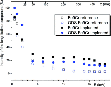 | ||
| Fig. 6 The intensity of the component(s) with positron lifetime > 260 ps. For the plotted data, a conservative estimate of the uncertainty is ± 5%. | ||
From the materials perspective and their performance under irradiation, it is interesting to compare the two materials with respect to the mean positron lifetime profile and displacement damage (dpa). The mean positron lifetime, as the statistically most reliable parameter, is virtually independent of the fitting procedure. A lifetime spectrum represented by the positron mean lifetime is similar to a fitting of the spectra by a single exponential function. It is, therefore, reasonable to compare the material performance in a radiation environment using this parameter. As shown in Fig. 7, for both materials, the positron lifetime significantly increases after the implantation, but the increase is much more pronounced in the conventional (non-ODS) f/m steel. This is in excellent agreement with the TEM analysis shown in Fig. 4, and it demonstrates the well-known improvement of the radiation resistance of nanostructured f/m steels. It is reasonable to assume that the high density of sub-granular interfaces is acting not only as recombination centres for radiation-induced defects but also as sinks for (transmutation) helium suppressing the helium bubble swelling.
| PALS (this study) | DBS (adopted from ref. 16) | |||||||
|---|---|---|---|---|---|---|---|---|
| Material | Fe9Cr | ODS Fe9Cr | Fe9Cr | ODS Fe9Cr | ||||
| Sample (reference/implanted) | Ref. | Impl. | Ref. | Impl. | Ref. | Impl. | Ref. | Impl. |
| a Bold = fixed values; in order to reduce the degrees of freedom and to obtain physically meaningful results, the highlighted parameters were fixed in the fitting procedure. Italics = reference materials bulk values. | ||||||||
| Fitting parameter L + [nm] | ||||||||
| Layer 1 | 3.77 ± 0.19 | 3.94 ± 0.04 | 0.77 ± 0.04 | 1.00 ± 0.01 | 2.26 ± 0.37 | 4.87 ± 0.40 | 4.36 ± 0.47 | 1.68 ± 0.12 |
| Layer 2 | 34.8 ± 0.69 | 0.49 ± 5.37 | 4.84 ± 0.29 | 0.5 | 10 | 50 | 3.5 | 20 |
| Layer 3 | 50 | 20 | 35 | 35 | 5 | 5 | ||
![[thin space (1/6-em)]](https://www.rsc.org/images/entities/char_2009.gif) |
||||||||
| Fitting parameter – layer boundary [nm] | ||||||||
| Layer 1 | 20 | 19.21 ± 5.61 | 20 | 36.86 ± 15.78 | 224.95 ± 12.25 | 399.1 ± 5.59 | 287.3 ± 13.29 | 531.6 ± 11.02 |
| Layer 2 | 351.7 ± 6.83 | 293.6 ± 5.99 | 1376.41 ± 13.90 | 2055.9 ± 9.84 | 1209.8 ± 18.58 | 2017.0 ± 26.58 | ||
![[thin space (1/6-em)]](https://www.rsc.org/images/entities/char_2009.gif) |
||||||||
| Fitting parameters | ||||||||
| τ mean [ns] | S-parameter | |||||||
| Layer 1 | 0.2812 ± 0.0010 | 0.4438 ± 0.0050 | 0.3204 ± 0.0012 | 0.45905 ± 0.0003 | 0.46![[thin space (1/6-em)]](https://www.rsc.org/images/entities/char_2009.gif) 016 ± 0.0003 016 ± 0.0003 |
0.45608 ± 0.0003 | 0.45987 ± 0.0003 | |
| Layer 2 | 0.1527 ± 0.0004 | 0.2201 ± 0.0005 | 0.1896 ± 0.0003 | 215.7 ± 0.0006 | 0.46![[thin space (1/6-em)]](https://www.rsc.org/images/entities/char_2009.gif) 751 ± 0.0002 751 ± 0.0002 |
0.50![[thin space (1/6-em)]](https://www.rsc.org/images/entities/char_2009.gif) 006 ± 0.0004 006 ± 0.0004 |
0.46450 ± 0.0003 | 0.48267 ± 0.0003 |
| Layer 3 | 0.2650 ± 0.0009 | 250.2 ± 0.0007 | 0.43![[thin space (1/6-em)]](https://www.rsc.org/images/entities/char_2009.gif) 949 ± 0.0006 949 ± 0.0006 |
0.39![[thin space (1/6-em)]](https://www.rsc.org/images/entities/char_2009.gif) 292 ± 0.0018 292 ± 0.0018 |
0.44![[thin space (1/6-em)]](https://www.rsc.org/images/entities/char_2009.gif) 672 ± 0.0005 672 ± 0.0005 |
0.50![[thin space (1/6-em)]](https://www.rsc.org/images/entities/char_2009.gif) 149 ± 0.0029 149 ± 0.0029 |
||
The VEPFIT analysis of the implanted samples was performed using a three-layer model. The first layer was considered to be identical with layer 1 in un-implanted samples and its upper boundary was found to be 19.2 nm and 36.9 nm, respectively. The second layer with a very short diffusion length (0.5 nm) was attributed to a region with relatively high displacement damage and negligible He concentration. The upper boundary of this layer was found to be 351.7 nm and 293.6 nm, respectively. According to the SRIM implantation profile, this corresponds to ∼3.5 dpa and ∼1500 appm He. These values are reasonably close to the displacement damage and helium concentration of f/m steels irradiated in spallation neutron target, investigated by PAS techniques at the Paul Scherrer Institute.31 Although the irradiation temperature in spallation neutron targets is typically higher than in the presented experiment, in both cases, the microstructure of irradiated f/m steel leads to a (nearly) saturated positron trapping.33 This explains the very short positron diffusion length as well as a very short positron bulk lifetime component. The diffusion length of positron in the third layer, starting at implantation depth > 300 nm was found to be L+ = 50 nm and L+ = 20 nm for Fe9Cr steel and the ODS Fe9Cr, respectively. These values are higher than the diffusion length in the unirradiated bulk. Based on the TEM results and the discussion in chapter 4.2.1, we assume that the positron trapping undergoes a transition to a diffusion-limited regime between the interface of layers 1 and 2 and the displacement damage peak, most likely in the region 600 ± 100 nm. This explains the unexpected increase in positron diffusion length along with the increase of positron mean lifetime between the reference and the irradiated condition (layer 3) of both studied materials.
The present results demonstrate both the effect of displacement damage and the effect of inert gas implanted in the microstructure. From the theoretical work of Troev et al.,36 it is known that the presence of helium can counterbalance the increase of positron trapping due to new radiation-induced defects. While helium-to-vacancy ratio close to 1 was obtained by theoretical37 and experimental38 methods for small vacancy clusters, a significantly lower ratio of helium is expected in large cavities. It is reasonable to assume that helium bubbles and large nanometric voids do not dramatically reduce the depth of the potential well for positrons. As a consequence, strong trapping at these cavities depletes the positron flux in their vicinity, and the positron trapping rate is not proportional to the positron diffusion length according to eqn (3). We assume that this scenario takes place at helium concentration > 10![[thin space (1/6-em)]](https://www.rsc.org/images/entities/char_2009.gif) 000 appm, i.e., in depth higher than ∼600 nm in the samples studied in this work.
000 appm, i.e., in depth higher than ∼600 nm in the samples studied in this work.
Our results show that the positron mean lifetime is very similar for the two studied materials after helium implantation, despite very different initial values. This, however, cannot be interpreted as the same performance under irradiation for two reasons. Firstly, the effect of helium on the reduction of positron trapping at small vacancy clusters is competing here with the effect of newly created vacancies, increasing the trapping. The qualitative and quantitative information on vacancy-type defects cannot be, therefore, easily obtained from the PALS measurements. The second reason is the limited effect of the vacancy-type defects on the performance of the irradiated material. Since the PAS analysis is not sensitive to interstitial-type defects, the comparison of PAS results with physical and mechanical properties will always be subject to error.
The fitted curve is shown together with the experimental lifetime values in Fig. 8. When considering the material bulk, as argued above, to be probed by positrons with E > 8 keV, we can conclude that the positron lifetime increased after implantation by 81.4 ps and 43.1 ps, for the Fe9Cr and its ODS variant, respectively. This is evidence of the presence of a higher density of recombination centres in the oxide dispersion strengthened steel, suppressing the formation of large defect agglomerations. Fig. 8b confirms the anticipated presence of an extra layer in the reference DBS samples, corresponding to microstructural defects introduced by mechanical polishing of these samples. This is indicated by the S-parameter peak in the region ∼500 nm. A similar feature, i.e., a peak in the mean lifetime values, was not observed in the PALS data. This points out the importance of the electropolishing step in the surface treatment of the samples.
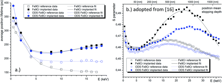 | ||
| Fig. 8 VEPFIT analysis of the positron lifetime depth profiles of the two studied materials in the pristine and implanted conditions (a). Analogous analysis of the Doppler depth profiles, adopted from our previous work (b).16 | ||
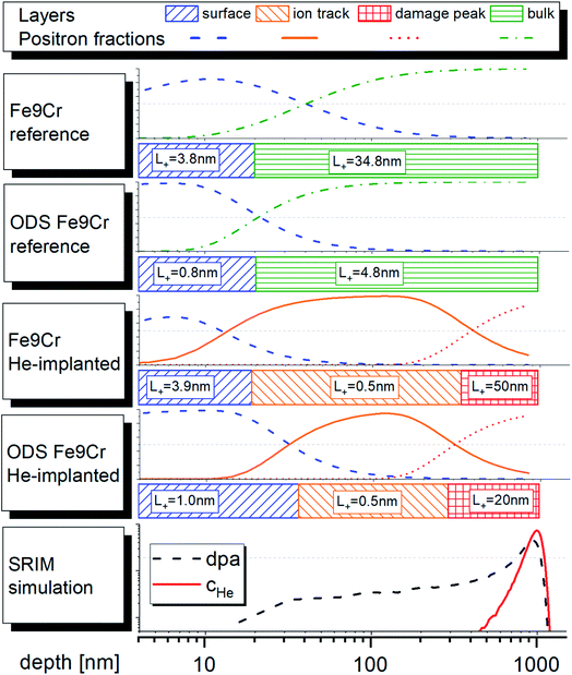
The schematic representation of the fitting models used in the VEPFIT analysis of all studied samples is shown in Fig. 9. The figure also shows the contribution (fractions) of positron annihilating in the individual layers as a function of depth. Note that thermal and epithermal positrons are not shown due to their small to negligible contribution.
Conclusions
The present work provides an innovative approach to the experimental study of inhomogeneous radiation damage in ion beam modified materials. Particular focus is placed on the investigation of materials bombarded with ions of an inert gas such as helium, which stabilises radiation-induced vacancy-type defects and represents a significant challenge in developing materials for many future nuclear installations.We showed that the positron diffusion length, which is an important parameter reflecting the microstructural damage of materials, can be obtained directly from the mean positron lifetime depth profiles. The results acquired from the VEPFIT analysis of the positron mean lifetime are in excellent agreement with the conventional approach based on the fitting of the Doppler broadening S-parameter depth profiles. Unlike conventional slow positron lifetime studies, the presented methodology enables the investigation of radiation-induced defects in the saturation of positron trapping when the missing contribution of free positrons excludes the quantitative characterization of lattice defects. By considering positron diffusion, we were able to extrapolate the meaningful outcome of the positron lifetime data towards the peak of the concentration of the defects produced by ion implantation. The reported methodology is particularly interesting for studies of complex materials like nanostructured alloys in which the positron trapping gets easily saturated.
The studied Fe9Cr f/m steel and its ODS variant showed both a significant reduction of the positron diffusion length in the helium implanted region, followed by a substantial increase in the helium peak region. This increase was attributed to the growth of helium bubbles, likely by coalescence, resulting in large volumetric defects which act as strong positron traps and lead to a diffusion-limited positron trapping.
The enhanced radiation tolerance of the ODS steel, indicated by the size distribution of large TEM-visible cavities, was also observed in the sub-nm size range by positron annihilation lifetime spectroscopy via a less pronounced increase of the positron lifetime. On the other hand, no significant indication of improved radiation tolerance has been observed for either of the materials at high displacement damage and helium concentration levels.
Conflicts of interest
There are no conflicts to declare.Acknowledgements
This work is based upon experiments performed at the PLEPS instrument operated at the FRM II reactor, Heinz Maier-Leibnitz Zentrum (MLZ), Garching, Germany. The authors acknowledge the contribution of the Slovak Research and Development Agency under the project APVV-20-0010. The authors further acknowledge financial contributions from the Scientific Grant Agency of the Ministry of Education, Science, Research and Sport of the Slovak Republic and the Slovak Academy of Sciences, grant numbers VEGA 1/0382/20 and VEGA 1/0395/20 and from the European Regional Development Fund project No. ITMS2014+:313011W085. This work is part of a project that has received funding from the Euratom Research and Training Programme 2019–2020 under grant agreement no. 945234.References
- D. Kiener, P. Hosemann, S. A. Maloy and A. M. Minor, In situ nanocompression testing of irradiated copper, Nat. Mater., 2011, 10, 608–613, DOI:10.1038/nmat3055.
- O. v. Ogorodnikova, M. Majerle, J. Čížek, S. Simakov, V. v. Gann, P. Hruška, J. Kameník, J. Pospíšil, M. Štefánik and M. Vinš, Positron annihilation spectroscopy study of radiation-induced defects in W and Fe irradiated with neutrons with different spectra, Sci. Rep., 2020, 10, 1–13, DOI:10.1038/s41598-020-75737-8.
- M. J. Konstantinovic and G. Bonny, Thermal stability and the structure of vacancy – solute clusters in iron alloys, Acta Mater., 2015, 85, 107–111, DOI:10.1016/j.actamat.2014.11.026.
- V. Slugeň, S. Pecko and S. Sojak, Experimental studies of irradiated and hydrogen implantation damaged reactor steels, J. Nucl. Mater., 2016, 468, 285–288, DOI:10.1016/j.jnucmat.2015.05.048.
- V. Krsjak, J. Degmova, S. Sojak and V. Slugen, Effects of displacement damage and helium production rates on the nucleation and growth of helium bubbles – Positron annihilation spectroscopy aspects, J. Nucl. Mater., 2018, 499, 38–46, DOI:10.1016/j.jnucmat.2017.11.007.
- L. Qiao, X. Zhang, R. He, H. Zhang and P. Wang, Influences of displacement damage due to heavy ion irradiation on deuterium retention in CLF-1 steel, Nucl. Mater. Energy, 2020, 25, 100794, DOI:10.1016/j.nme.2020.100794.
- C.-L. Chen, A. Richter, R. Kögler and G. Talut, Dual beam irradiation of nanostructured FeCrAl oxide dispersion strengthened steel, J. Nucl. Mater., 2011, 412, 350–358, DOI:10.1016/j.jnucmat.2011.03.041.
- E. Wakai, T. Sawai, K. Furuya, A. Naito, T. Aruga, K. Kikuchi, S. Yamashita, S. Ohnuki, S. Yamamoto, H. Naramoto and S. Jitsukawa, Effect of triple ion beams in ferritic/martensitic steel on swelling behavior, J. Nucl. Mater., 2002, 307, 278–282, DOI:10.1016/S0022-3115(02)01076-0.
- S. Agarwal, M. O. Liedke, A. C. L. Jones, E. Reed, A. A. Kohnert, B. P. Uberuaga, Y. Q. Wang, J. Cooper, D. Kaoumi, N. Li, R. Auguste, P. Hosemann, L. Capolungo, D. J. Edwards, M. Butterling, E. Hirschmann, A. Wagner and F. A. Selim, A new mechanism for void-cascade interaction from nondestructive depth-resolved atomic-scale measurements of ion irradiation-induced defects in Fe, Sci. Adv., 2020, 6 DOI:10.1126/sciadv.aba8437.
- B. Li, V. Krsjak, J. Degmova, Z. Wang, T. Shen, H. Li, S. Sojak, V. Slugen and A. Kawasuso, Positron annihilation spectroscopy study of vacancy-type defects in He implanted polycrystalline α-SiC, J. Nucl. Mater., 2020, 535, 152180, DOI:10.1016/j.jnucmat.2020.152180.
- V. Sabelova, V. Krsjak, J. Kuriplach, M. Petriska, V. Slugen and J. S. Veternikova, Characterization of helium implanted Fe-Cr alloys by means of positron annihilation methods, J. Nucl. Mater., 2014, 450, 54–58 CrossRef CAS.
- A. Debelle, M. F. Barthe, T. Sauvage, R. Belamhawal, A. Chelgoum, P. Desgardin and H. Labrim, Helium behaviour and vacancy defect distribution in helium implanted tungsten, J. Nucl. Mater., 2007, 362, 181–188, DOI:10.1016/j.jnucmat.2007.01.021.
- V. Krsjak, J. Degmova, J. S. Veternikova, C. F. Yao and Y. Dai, Experimental comparison of the (ODS)EUROFER steels implanted by helium ions and irradiated in spallation neutron target, J. Nucl. Mater., 2019, 523, 51–55, DOI:10.1016/j.jnucmat.2019.05.044.
- M. Šćepanović, V. de Castro, I. García-Cortés, F. J. Sánchez, T. Gigl, C. Hugenschmidt and T. Leguey, Characterisation of open volume defects in Fe–Cr and ODS Fe–Cr alloys after He+ and Fe+ ion irradiations, J. Nucl. Mater., 2020, 538, 152230, DOI:10.1016/j.jnucmat.2020.152230.
- R. Krause-Rehberg, V. Bondarenko, E. Thiele, R. Klemm and N. Schell, Determination of absolute defect concentrations for saturated positron trapping - Deformed polycrystalline Ni as a case study, Nucl. Instrum. Methods Phys. Res., Sect. B, 2005, 240, 719–725, DOI:10.1016/j.nimb.2005.04.130.
- J. Degmová, V. Kršjak, T. Shen, J. Šimeg Veterniková, A. Gatciová, S. Sojak and P. Hruška, Near-surface investigation of positron diffusion length in helium-implanted Fe9Cr and its ODS variant, Appl. Surf. Sci., 2021, 538 DOI:10.1016/j.apsusc.2020.148004.
- W. Egger, PLEPS: Pulsed low energy positron system, Journal of Large-Scale Research Facilities, 2015, 1 DOI:10.17815/jlsrf-1-52.
- C. Hugenschmidt and C. Piochacz, NEPOMUC: Neutron induced positron source Munich, Journal of Large-Scale Research Facilities, 2015, 1 DOI:10.17815/jlsrf-1-49.
- P. Hautojärvi and A. Vehanen, Introduction to Positron Annihilation, in Positrons in Solids, ed. P. Hautojärvi, Springer Berlin Heidelberg, Berlin, Heidelberg, 1979, pp. 1–23, DOI:10.1007/978-3-642-81316-0_1.
- M. Klimiankou, R. Lindau and A. Möslang, Direct correlation between morphology of (Fe, Cr) 23 C 6 precipitates and impact behavior of ODS steels, J. Nucl. Mater., 2007, 367–370, 173–178, DOI:10.1016/j.jnucmat.2007.03.150.
- P. Noga, J. Dobrovodsky, D. Vana, M. Beno, A. Zavacka, M. Muska, R. Halgas, S. Minarik and R. Riedlmajer, A new ion-beam laboratory for materials research at the Slovak University of Technology, Nucl. Instrum. Methods Phys. Res., Sect. B, 2017, 409, 264–267, DOI:10.1016/j.nimb.2017.04.051.
- M. J. Norgett, M. T. Robinson and I. M. Torrens, A proposed method of calculating displacement dose rates, Nucl. Eng. Des., 1975, 33, 50–54, DOI:10.1016/0029-5493(75)90035-7.
- J. F. Ziegler, M. D. Ziegler and J. P. Biersack, SRIM – The stopping and range of ions in matter (2010), Nucl. Instrum. Methods Phys. Res., Sect. B, 2010, 268, 1818–1823, DOI:10.1016/j.nimb.2010.02.091.
- D. Giebel and J. Kansy, LT10 Program for Solving Basic Problems Connected with Defect Detection, Phys. Procedia, 2012, 35, 122–127, DOI:10.1016/j.phpro.2012.06.022.
- J. S. Veternikova, J. Degmova, V. Sabelova, M. Petriska and V. Slugen, Surface study of radiation damaged oxide dispersion strengthened steels, Appl. Surf. Sci., 2014, 312, 199–202, DOI:10.1016/j.apsusc.2014.02.146.
- A. B. Walker, Positron slowing down and surface processes, AIP Conf. Proc., 1991, 218, 29–33, DOI:10.1063/1.40199.
- P. J. Schultz and K. G. Lynn, Interaction of positron beams, Rev. Mod. Phys., 1988, 60, 701–779 CrossRef CAS.
- V. Krsjak, J. Kuriplach, C. Vieh, L. Peng and Y. Dai, On the empirical determination of positron trapping coefficient at nano-scale helium bubbles in steels irradiated in spallation target, J. Nucl. Mater., 2018, 504, 277–280, DOI:10.1016/j.jnucmat.2018.03.045.
- A. van Veen, H. Schut, J. de Vries, R. A. Hakvoort and M. R. Ijpma, Analysis of positron profiling data by means of ‘“VEPFIT, AIP Conf. Proc., 1991, 218, 171–198, DOI:10.1063/1.40182.
- M. Eldrup and K. O. Jensen, Positron Trapping Rates into Cavities in Al: Temperature and Size Effects, Phys. Status Solidi A, 1987, 102, 145–152, DOI:10.1002/pssa.2211020114.
- Y. Dai, V. Krsjak, V. Kuksenko and R. Schäublin, Microstructural changes of ferritic/martensitic steels after irradiation in spallation target environments, J. Nucl. Mater., 2018, 511, 508–522, DOI:10.1016/j.jnucmat.2018.09.028.
- H. F. M. Mohamed, J. Kwon, Y.-M. Kim and W. Kim, Vacancy-type defects in cold-worked iron studied using positron annihilation techniques, Nucl. Instrum. Methods Phys. Res., Sect. B, 2007, 258, 429–434, DOI:10.1016/j.nimb.2007.02.073.
- V. Krsjak, J. Kuriplach, T. Shen, V. Sabelova, K. Sato and Y. Dai, Helium behavior in ferritic/martensitic steels irradiated in spallation target, J. Nucl. Mater., 2015, 456, 382–388, DOI:10.1016/j.jnucmat.2014.10.014.
- J. M. Urban-Klaehn, K. L. Gering, C. N. Taylor and C. A. Quarles, Positron Parameters for Atypical Samples, Acta Phys. Pol., A, 2020, 137, 201–204, DOI:10.12693/APhysPolA.137.201.
- I. Carvalho, H. Schut, A. Fedorov, N. Luzginova, P. Desgardin and J. Sietsma, Helium implanted RAFM steels studied by positron beam Doppler Broadening and Thermal Desorption Spectroscopy, J. Phys.: Conf. Ser., 2013, 443, 12034, DOI:10.1088/1742-6596/443/1/012034.
- T. Troev, A. Markovski, S. Peneva and T. Yoshiie, Positron lifetime calculations of defects in chromium containing hydrogen or helium, J. Nucl. Mater., 2006, 359, 93–101, DOI:10.1016/j.jnucmat.2006.07.020.
- R. E. Stoller and Y. N. Osetsky, An atomistic assessment of helium behavior in iron, J. Nucl. Mater., 2014, 455, 258–262, DOI:10.1016/j.jnucmat.2014.06.020.
- V. Krsjak, Recent Progress on the Positron Annihilation Experiments on Irradiated Ferritic/Martensitic Steels Containing Helium, Mater. Sci. Forum, 2021, 1024, 1–12 Search PubMed.
Footnote |
| † While the positron lifetime values obtained from the deconvolution of the PALS spectra are commonly attributed to particular bulk materials or particular lattice defects, the experimental DBS spectrum cannot be “deconvoluted” into bulk and defect component in such manner. Yet, it is clear that the annihilation of free positrons and positrons trapped at defects results in different shape of the broadened DBS profiles. |
| This journal is © The Royal Society of Chemistry 2021 |

