 Open Access Article
Recent developments of hybrid piezo–triboelectric nanogenerators for flexible sensors and energy harvesters
Jin
Zhang
 *a,
Yilin
He
a,
Cyrille
Boyer
 *b,
Kourosh
Kalantar-Zadeh
 b,
Shuhua
Peng
 a,
Dewei
Chu
 c and
Chun H.
Wang
 *a
*a
aSchool of Mechanical and Manufacturing Engineering, University of New South Wales (UNSW), Sydney, NSW 2052, Australia. E-mail: jin.zhang6@unsw.edu.au; chun.h.wang@unsw.edu.au
bSchool of Chemical Engineering, UNSW, Building E8, Sydney, Kensington, NSW 2052, Australia. E-mail: cboyer@unsw.edu.au
cSchool of Materials Science and Engineering, UNSW, Building E10, Sydney, Kensington, NSW 2052, Australia
First published on 19th July 2021
Abstract
Hybrid piezo–triboelectric nanogenerators constitute a new class of self-powered systems that exploit the synergy of piezoelectric and triboelectric mechanisms to improve energy harvesting efficencies and address the energy and power needs of portable and wearable electronic devices. The unique, synergistic electrical coupling mechanisms of piezoelectric and triboelectric effects increase the electric outputs and energy conversion efficiency of hybrid generators to beyond a linear summation of the contributions from individual triboelectric and piezoelectric mechanisms. Due to their large surface-area-to-volume ratios and outstanding mechanical, electronic and thermal properties, nanomaterials are favourable building blocks for constructing hybrid nanogenerators and represent a large family of flexible energy harvesting electronic structures and devices. Herein, we review the recent advances of hybrid piezo–triboelectric nanogenerators, with a particular focus on microstructure design, synergy mechanisms, and future research opportunities with significant potential for physiological monitoring, health care applications, transportation, and energy harvesting. The main strategies for improving electrical output performance are identified and examined, including novel nanostructures for increasing the contact area of the triboelectric pair, and nano-additives for enhancing the surface potential difference between the triboelectric pair and piezoelectric layers. Future applications and commercialization opportunities of these nanogenerators are also reviewed.
Introduction
Flexible electronics, portable and wearable devices have attracted significant interest for research and applications in recent years. Passive sensor systems require batteries as a power source and thus can be inconvenient for many applications due to the need for frequent charging and replacement. What's more, batteries are generally the heaviest and bulkiest components of electronic systems, which also limit portability and inhibit the incorporation of electronic devices into clothing without affecting wearing comfort. An appealing solution is to scavenge and harvest energy from the surrounding environment and to convert waste energy to electrical energy. For example, abundant mechanical energies from human motion, airflow, water waves, and water flow are wasted. If converted to electricity, they can reduce or eliminate the need for batteries, making sensor systems self-powered and providing an effective and green approach to tackling global issues such as the depletion of non-renewable energy resources and inconvenience of battery charging/replacement.1 Taking human activity as an example, footsteps or arm movement from a typical person (68 kg) can generate kinetic powers of around 67 W and 60 W, respectively, while breathing and finger typing can generate 0.83 W and 6.9 mW, respectively.2 Current on-body electronics require 200 μW to 1 W, which can be met by scavenging biomechanical energy from human motion.Since ‘piezoelectric vibration-powered microgenerators’ were proposed by P. Glynne-Jones in 2001,3 the concept of nanogenerators was expanded by Z. L. Wang in the early 2000s using piezoelectric zinc oxide (ZnO) nanowire arrays for converting mechanic disturbance from an atomic force microscope to electrical energy.4 Since then, a tremendous amount of research, based on various nanostructures and nanoarchitectures, has been reported for converting mechanical energy to electric energy based on piezoelectric or triboelectric effects. Compared with traditional mechanical energy generators (e.g. hydraulic generators and wind power generators), nanogenerators possess many advantages such as being small scale, low cost, facile fabrication, and portability.5,6
The piezoelectric effect refers to the phenomenon that the polarizations of piezoelectric materials change when they are subjected to mechanical stress, either because of the reconfiguration of the dipole-inducing surrounding or the reorientation of molecular dipole moments, resulting in positive and negative electric center shifts that generate an electric field.7 The piezoelectric effect can be reversible, i.e., the application of an electrical charge can generate mechanical strain, and can operate in a wide frequency range and many motion modes. Piezoelectric crystals can be conveniently reduced to nanosized fillers that retain the piezoelectricity for the assembly of nanogenerators. Nanofillers include zero-dimensional (0D) materials such as barium titanate (BTO)8 and potassium sodium niobate (KNN) nanoparticles;9 one-dimensional (1D) materials such as lead zirconate titanate (PZT) nanofibres,10 zinc oxide (ZnO) nanorods, gallium nitride (GaN),11 and indium nitride (InN) nanowires;12 and two-dimensional (2D) fillers such as tin disulfide (SnS2)13 and molybdenum disulfide (MoS2) nanosheets.14 Piezoelectric polymers based on polyvinylidene difluoride (PVDF) and their nanocomposites are also predominately used for developing piezoelectric nanogenerators.
By contrast, the triboelectric effect relies on contact-induced electrification when two electrically-charged materials move relatively to each other. This occurs by friction after materials make contact (contact-separate or sliding modes).15 The polarity of the induced charge is directly related to the relative polarity of the triboelectric pair. Nanomaterials such as 0D nanoparticles (e.g. Ag nanoparticles16), 1D nanowires and nanofibres,17 and 2D nanosheets (e.g. h-BN,18 metal–organic frameworks (MOFs)19 and transition metal dichalcogenides (TMDs)20) have been utilized to modify electrode or/and triboelectric materials to induce and enhance triboelectricity, by reducing internal resistance, and augment charge generation or supply extra charge trapping sites.21
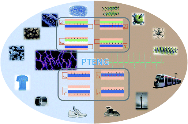
Although piezoelectric nanogenerators (PENGs) and triboelectric nanogenerators (TENGs) operate under different mechanisms, they can be integrated to enhance the total power output because they both have several common features during mechanical-to-electrical energy conversion. Importantly, both mechanisms work well under mechanical deformation by compression, deflection and vibration. Additionally, the two effects do not overlap during electricity generation since the triboelectrification occurs on the surfaces of materials, while the piezoelectric phenomenon takes place in the bulk below the surface.22 These features make the hybridization of the PENG and TENG (PTENG) feasible when both mechanical deformation and contact friction of materials occur simultaneously by the rational design of the device structure and polarization direction modulations, increasing energy scavenging and conversion efficiency23 (Fig. 1). One evident advantage of hybrid PTENG is the increased output current and voltage, which brings great potential for efficiently powering wearable electronic devices.
There is an increasing demand for flexible nanogenerators that can harvest biomechanical energy from human movements such as arm swings, leg motions, heel strikes and elbow joint motion. For wearable technologies, flexibility is an essential performance requirement for wear comfort and the convenience of the wearer. To achieve high flexibility (but not stretchability), thin polymer films or fibrous materials are used as structural constitutes of PTENGs to be able to scavenge energy from a broad range of human movements in low frequency ranges and to increase their sensitivity and durability as well.24,25 The present review examines advances in structural designs of flexible PTENGs, the coupling effect between piezoelectric and triboelectric effects, methods for enhancing electrical outputs, their niche applications in practical self-powered sensors and energy harvesters, and challenges for the further development of PTENGs.
Structure design of piezo–triboelectric hybrid nanogenerators
The multifunctionality and performance of hybrid piezo–triboelectric nanogenerators are closely related to their structure design. The structure of PTENGs is mainly divided into two major types: three-electrode modules and two-electrode modules, which are discussed in the following sections.Three-electrode modules
The strategy of the three-electrode module design is to introduce the piezoelectric and triboelectric functional layers separately. Usually, these layers are separated by introducing an electrode in between, with two triboelectric layers working in the contact-separation mode.26 Assuming that a dielectric triboelectric layer is in contact with a conductive tribolayer, which doubles as an electrode, to obtain negative charges during compression, the negative and positive piezoelectric charges develop on the upper and lower surfaces of a PTENG shown in Fig. 2a. First, the pre-rubbed triboelectric layer and the middle electrode are close to each other until they come into contact. In this process, due to the enhanced electrostatic induction, the positive charges in the upper electrode are attracted to the middle electrode, generating a triboelectric current from the bottom to the top in the upper half of the circuit. Subsequently, the continuous application of compression causes the piezoelectric layer to generate piezoelectric charges. Under electrostatic induction, some of the negative charges in the middle electrode are transferred to the lower electrode, and a corresponding piezoelectric current is generated in the lower half of the circuit. After the pressure is released, the piezoelectric charges disappear. The piezoelectric charges are transferred by electrostatic induction in the lower half of the circuit then flow back to the original location. Simultaneously, a current opposite to the piezoelectric current is generated in the lower half of the circuit. Finally, when the distance between the triboelectric layer and the middle electrode gradually increases from zero to the maximum, the electrostatic induction between the triboelectric layer and the middle electrode degrades gradually until complete disappearance. The positive charges attracted to the middle electrode by electrostatic induction previously return to the upper electrode, generating a triboelectric current from top to bottom in the upper half of the circuit. Table 1 shows a number of PTENG examples with three-electrode structure consisting of different materials.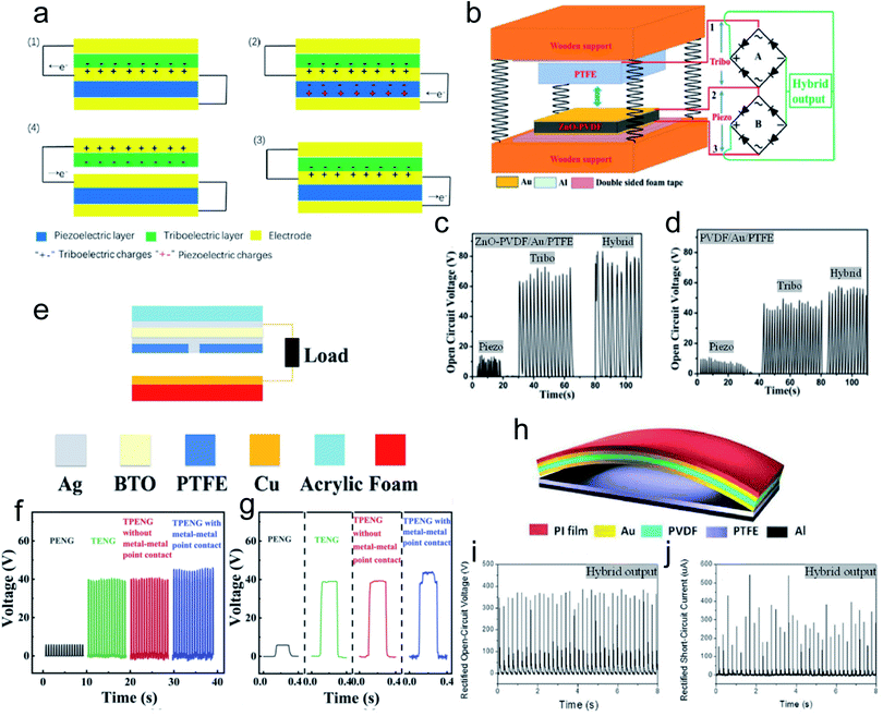 | ||
| Fig. 2 PTENG with the three-electrode module and the optimized design examples. (a) Working cycle of the three-electrode PTENG. (b) Schematic structure and electro-circuit diagram of a ZnO nanorod/PVDF-PTFE based PTENG. (c) Open-circuit voltage of the PVDF film with ZnO nanorods working under piezo\tribo\hybrid mode. (d) Open-circuit voltage of the PVDF film without ZnO working under piezo\tribo\hybrid mode. Reproduced with permission.33 Copyright 2018, Elsevier. (e) Schematic structure diagram of a PTENG with point contact between two electrodes. (f) Comparison of the open-circuit voltages for different working modes of the generator and their enlarged view (g). Reproduced with permission.34 Copyright 2020, Elsevier. (h) Schematic structure diagram of an arc-shaped PVDF-PTFE based PTENG. (i) Open-circuit voltage of the arc-shaped PVDF-PTFE based PTENG. (j) Short-circuit current of the arc-shaped PVDF-PTFE based PTENG. Open access under a Creative Commons Attribution 4.0 International License.32 | ||
| Triboelectric constitutes with fillers | Piezoelectric constitutes with fillers | Output voltage | Output current | Output power | Ref. |
|---|---|---|---|---|---|
| Silicon rubber with PTFE particles & silicon rubber with silver coated spheres | PZT powder | 600 V | 17 μA | 1.11 W m−2 | 27 |
| Polydimethylsiloxane (PDMS) & carbon nanotube (CNTs) & graphite nanoparticle | PVDF & carbon nanotube & BTO nanofibre | 160 V | — | 2.22 W m−2 | 28 |
| PDMS & graphite nanoparticles | PVDF – trifluoroethylene (PVDF-TrFE) & Ag nanowire | 190 V | — | 16.46 μW | 29 |
| Cellulose paper & MoS2 nanosheet & polyimide (PI) | PVDF nanofibre | 50 V | 30 nA | 0.18 mW cm−2 | 30 |
| Acrylic & Al | PVDF film | 180 V | 5.3 μA | 127 μW | 31 |
For instance, Jung et al. introduced a PTENG with the three-electrode module.32 In their work, the piezoelectric layer formed the middle layer of a sandwich structure where a layer of gold (Au) was deposited on both surfaces of the piezoelectric PVDF film. The triboelectric layers consist of a polytetrafluoroethylene (PTFE) film and an aluminum (Al) electrode. To utilize the contact-separation operation mechanism, the piezoelectric PVDF layer was bent and connected to the triboelectric PTFE layer by the edge, creating an arc-shape structure (Fig. 2h). With this design, the hybrid nanogenerator was able to produce an output power of 4.44 mW m−2. Singh et al. demonstrated another representative three-electrode module example.33 They prepared a typical module for the PTENG, which consisted of a PTFE electrification layer, a spacer, and a ZnO nanorod-filled piezoelectric PVDF film functional layer. The schematic of the three-electrode device is illustrated in Fig. 2b and it generates an impressive output power of 250 mW m−2.
The three-electrode design is a simple structure module for PTENGs, and the fabrication of its triboelectric and piezoelectric functional parts almost does not interfere with each other. This structure facilitates the enhancements of piezoelectric or triboelectric properties. However, this separation design requires a shared electrode and sometimes two external circuits are needed to harvest the electricity generated from piezoelectric and triboelectric effects separately, which complicates the packaging and increases the volume of the device.
To mitigate the aforementioned disadvantage, researchers have tried to optimize the three-electrode module structure. Zhu et al. reported an innovative design of an all-in-one PTENG with point contact and its adjustable charge transfer by ferroelectric polarization.34 In their work, the device was assembled as a layer-stacking structure, and the functional layers were arranged following the sequence of a top piezoelectric electrode, piezoelectric layer, bottom piezoelectric electrode, triboelectric layer, spacer, and bottom triboelectric electrode (Fig. 2e). Several holes were drilled into the triboelectric layer to prevent the complete isolation of the lower piezoelectric electrode and the triboelectric electrode. When the device was driven under external force, the upper silver (Ag) electrode, the PTFE film, and the lower copper (Cu) electrode functioned as a normal contact-separation TENG using an external circuit. Once the upper part of the device came into contact with the lower part, with the exertion and release of external force, the piezoelectric charges generated by the BTO (BaTiO3) nanoparticles/PVA sheet transferred between the Ag and Cu electrode junction at the PTFE holes; then the electrostatic balance was achieved through the same external circuit as the triboelectric part.
Two-electrode modules
The two-electrode design is a structure that has only one functional layer but combines both triboelectric and piezoelectric properties; the functional layer being sandwiched between two electrodes. A spacer is usually required between one of the electrodes and the functional layer.35 Assuming the piezoelectric layer acquires negative charges during friction, and the piezoelectric charge distribution when it is pressed is up negative and down positive, the working cycle of the two-electrode PTENG is divided into four stages (Fig. 3a). First, the upper electrode of the pre-rubbed generator moves close to the piezoelectric layer until they touch each other. During this process, as the electrostatic induction between the piezoelectric layer and the upper electrode gradually increases, positive charges flow from the lower electrode through the external circuit to the upper electrode, generating a triboelectric current from top to bottom in the external circuit. As the applied pressure increases, piezoelectric bound charges are then generated inside the piezoelectric layer due to the piezoelectric effect. Because of the electrostatic induction of the piezoelectric charges, the negative charges in the upper electrode flow to the lower electrode, causing a piezoelectric current from top to bottom in the external circuit. When the pressure is removed, the piezoelectric charge disappears, and the charges generated by the piezoelectric effect in the electrode flow back to its original position to achieve electrostatic balance. This process produces a piezoelectric current in the direction opposite to that of the first piezoelectric current. Finally, when the distance between the upper electrode and the piezoelectric layer increases gradually, the electrostatic induction between them becomes weaker. The excess positive charge flows from the upper electrode to the lower electrode, forming a triboelectric current in the external circuit opposite to the first triboelectric current.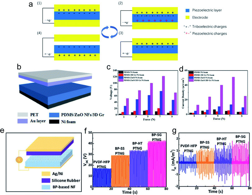 | ||
| Fig. 3 PTENG with the two-electrode module and examples of the device and performance. (a) Working cycle of a two-electrode PTENG. (b) Schematic structure diagram of a PDMS/ZnO nanoflakes/3D graphene based PTENG. (c) Comparison of the open-circuit voltage under different loads among PDMS/Ni foam, PDMS/3D graphene/Ni foam, PDMS/ZnO nanoflakes/Ni foam, and PDMS/ZnO nanoflakes/3D graphene/Ni foam based PTENGs. (d) Comparison of the short-circuit current under different loads among PDMS/Ni foam, PDMS/3D graphene/Ni foam, PDMS/ZnO nanoflakes/Ni foam, and PDMS/ZnO nanoflakes/3D graphene/Ni foam based PTENGs. Reproduced with permission from ref. 36. Copyright (2018) American Chemical Society. (e) Schematic structure diagram of a BCZT/PVDF nanofibre based PTENG. (f) Comparison of the open-circuit voltage of the PTENG with different enhancements. (g) Comparison of the short-circuit current density of the PTENG with different enhancements. Reproduced from ref. 42 with permission from the Royal Society of Chemistry. | ||
Qian et al. recently demonstrated a hybrid nanogenerator prepared from PDMS/ZnO nanoflakes/three-dimensional (3D) graphene heterostructures with a two-electrode structure.36 In their work, 3D graphene was first deposited on a nickel (Ni) foam by chemical vapor deposition (CVD), and the ZnO nanoflakes were produced on the graphene using the solution growth method. PDMS was then spin-coated onto the ZnO nanoflakes/3D graphene/Ni foam substrate to form the functional layer and the bottom electrode. The hybrid energy harvesters were fabricated by assembling a polyethylene terephthalate (PET)/Au electrode with the functional part (Fig. 3b). The PTENG showed peak-to-peak output voltages up to 122 V and peak-to-peak current densities up to 51 μA cm−2, leading to an ultrahigh power density of 6.22 mW cm−2. Table 2 shows a number of PTENG examples with two-electrode structure with different constituent materials.
| Triboelectric constitute with fillers | Piezoelectric constitute with fillers | Output voltage | Output current | Output power | Ref. |
|---|---|---|---|---|---|
| Chitosan & PTFE | Chitosan & BaTiO3 nanorods | 247.2 V | 36.7 μA cm−2 | 1568 μW cm−2 | 37 |
| Nickel/copper-coated PET-conductive fabric & PVDF | PVDF nanofibres | 210 V | 45 μA | 2.1 mW | 38 |
| PDMS & multi-walled CNTs & ZnO nanoflower | ZnO nanoflower | 400 V | 30 μA | — | 39 |
| PDMS | Calcium doped BZT powder | 550 V | 34 μA | 23.6 W m−2 | 40 |
| PDMS | BaTiO3 nanoparticle | 280 V | 5.6 μA | 0.04 mW cm−2 | 41 |
Wu et al. also fabricated a PTENG based on piezoelectric composite nanofibres and silicone rubber with this two-electrode module.42 The device was prepared as a four-layer structure (Fig. 3e). Instead of using direct contact of the electrode and tribo layer, a piece of silicone rubber was added between the top electrode and the tribo-piezoelectric function layer as another friction counterpart. The piezoelectric layer of the device was made from a PVDF nanofibre network with (Ba0.85Ca0.15)(Zr0.1Ti0.9)O3 (BCZT) nanoparticles as fillers. Because the silicone rubber was more electronegative than PVDF, the silicone rubber became negatively charged during the triboelectric process while the PVDF matrix received positive charges. Besides, the poling direction of the PVDF/BCZT composite fibre network was consistent with the charge flow direction of triboelectricity by controlling the direction of the electrical field applied to the BCZT-based PVDF nanofibres during the electrospinning process to increase the output of the hybrid device. The final output power density of this generator reached 162 mW m−2, representing 5.5-fold enhancement in comparison with that of a BTO/PVDF-based composite PTENG.
Piezoelectric and triboelectric coupling effects
The hybridization of the piezoelectric and triboelectric effects does not merely result in a simple summation of their output performance. This has been proved in many previous studies on hybridization between piezoelectric and triboelectric effects. Wang et al.43 reported that during the operation of their hybrid PTENG device, the piezoelectric part generated a peak output power density of 84 mW m−2, which was about 13 times higher than that obtained when the piezoelectric effect acted alone. This piezoelectric property enhancement was suggested to be a side effect of the triboelectric charge accumulation. In their three-electrode module (Fig. 4c), upon contact between the tribo-layer and the top Cu electrode of the piezo-part, there were positive tribo-charges accumulated on the top Cu electrode. The accumulated tribo-charges created an electrical field in the piezoelectric layer, which affected the polarization of the piezoelectric materials. Thus, when the intrinsic poling direction of the piezoelectric material aligned with the electrical field generated by the triboelectric charges, the overall output of the hybrid device was enhanced and vice versa.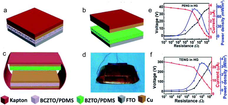 | ||
| Fig. 4 A PTENG based on the (Ba0.838Ca0.162)(Ti0.9072Zr0.092)O3 (BCZTO)/PDMS composite and Ba(Ti0.8Zr0.2)O3 (BZTO)/PDMS composite. (a–c) Schematic of the piezoelectric part, triboelectric part and hybrid structure. (d) Photo of the BCZTO/PDMS-BZTO/PDMS based PTENG. (e) The output performance of the PENG working under hybrid mode with different loaded resistances. (f) The output performance of the TENG working under hybrid mode with different loaded resistances. Reproduced from ref. 43 with permission of AIP Publishing. | ||
Another typical example is given by Hassan et al.44 They presented a hybrid device that combined a ZnSnO3 based PENG and a PDMS based TENG. These two parts were separated by a common Cu electrode. When the PENG worked independently, the peak voltage output was around 6 V. After being hybridized with a TENG, the output voltage increased to 62.5 V.
Finite element modelling (FEM) was conducted by Han et al. using COMSOL to analyze the impact of tribo charges on the piezoelectricity of the hybrid generator.45 In their simulation, a PVDF film was placed on a PDMS substrate and the lower surface of the PVDF film and the upper surface of the PDMS substrate were charged with equivalent opposite charges (positive charges in PVDF and negative charges in PDMS). When the PVDF film was bent to produce a piezoelectric potential with zero surface charge density in the interface, the original piezoelectric potential was 146.2 V. With the increase of surface charge density from 0 to 10 μC m−2 and 20 μC m−2, the piezoelectric potential was enhanced to 147.3 V and 153.0 V, respectively. The simulation results were also validated by experimental results, i.e. the output voltage increased from 68.4 V to 81.6 V when the substrate changed from Al to PDMS.
The triboelectric part of the hybrid nanogenerator is usually fabricated using different types of friction materials, which have dissimilar surface potentials to enable the charge transfer during the triboelectric process. However, it has been proved that when piezoelectric materials like PVDF are directly used as the triboelectric layer or added to the triboelectric layer, the intrinsic dipole moment alters the materials' surface potential. This phenomenon allows the charges to transfer during the contact process, even if the paired materials are the same.46 Yousry et al. constructed a theoretical module of a two-electrode hybrid nanogenerator using two PVDF fibre mats as both the triboelectric and the piezoelectric layers to address this issue.47 As shown in Fig. 5d, the two PVDF fibre mats were poled in the same direction. When the paired PVDF nanofibre mats came into contact and were pressed under external force, opposite piezoelectric charges were generated on the top and bottom surfaces of the two PVDF fibre mats. This effect differentiates the potential of the two contact surfaces of the two PVDF fibre mats so that tribo charge transfer can occur between them.
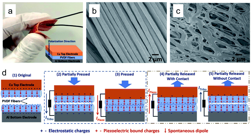 | ||
| Fig. 5 A PTENG based on aligned electrospun polyvinylidene fluoride (PVDF) fibre mats. (a) Photo and schematic of the PVDF fibre energy harvesting device. SEM image of the bundles of the aligned as-spun fiber (b) and melted at 185 °C (c). (d) Constructive piezoelectric–triboelectric effect in PVDF fibres with aligned electrical polarization. Reproduced with permission.47 Copyright 2020, John Wiley and Sons. | ||
The above-described mechanism has been employed in the PTENG design to increase the triboelectric output. Narasimulu et al. assembled a PTENG device with multilayers: the top electrode, polyamide 6 (PA6) friction layer, PVDF/ZnSnO3 nanocube/ZnO nanosheet functional layer, and bottom electrode.48 The PVDF/ZnSnO3 nanocube/ZnO nanosheet layer was regarded as the piezoelectric functional layer and the triboelectric pair with the PA6 film in this design. During the operation, the negative piezoelectric charges generated by PVDF and ZnO nanosheets resulted in an upper surface potential decrease in the PVDF/ZnSnO3/ZnO film. Thus, the contact surface potential difference between PA6 and PVDF increased, leading to an increase in transferred triboelectric charges during the contact between the PA6 film and the PVDF/ZnSnO3/ZnO film, which therefore significantly improved the triboelectric output. With this piezoelectric charge inducing mechanism, the output power density of the hybrid nanogenerator could significantly increase from 110 mW m−2 to 1800 mW m−2.
Piezo–triboelectric nanogenerator output enhancement considerations
Since the hybrid nanogenerator can be regarded as a triboelectric generator and a piezoelectric generator integrated through structural design, technologies used for improving the triboelectric and piezoelectric performance can also be applied to improve the total output performance of the hybrid PTENG (Table 3).| Nanogenerator constitute materials | Enhancement aspect | Enhancement strategies | Output voltage before enhancement | Output voltage after enhancement | Ref. |
|---|---|---|---|---|---|
| PDMS & PVDF-TrFE/0.78Bi0.5Na0.5TiO3–0.22SrTiO3 nanofibres | Triboelectricity | Enlarge the contact area: roughen the surface | 219 V | 253 V | 49 |
| Spider silk & PET& PVDF/graphene nanosheets | Triboelectricity | Increase surface potential differences: Adding PVDF | 95 V | 208 V | 50 |
| PVDF/BTO nanoparticles & PA6 | Piezoelectricity | Increase the piezoelectric constant: Adding BaTiO3 nanoparticles | 384 V | 900 V | 51 |
| PDMS/ZnO nanoflower/MWCNT | Piezoelectricity | Increase the piezoelectric charge transfer rate: adding MWCNTs | 89.06 V | 150 V | 39 |
| PDMS/BaTiO3 nanopowder/Ti0.8O2 nanosheets/Ag nanoparticles | Piezoelectricity | Increase the piezoelectric constant and charge transfer rate: adding Ti0.8O2 nanosheets and Ag nanoparticles | 8 V | 150 V | 52 |
Triboelectric effect enhancement
In a typical contact-separate module (one dielectric layer with two electrodes) TENG, its open-circuit voltage (Voc) and short-circuit current (Qsc) can be represented by the following equations:53 | (1) |
 | (2) |
To improve the triboelectric effect, Yu et al. summarized the main approaches including creating micro/nano structures (to increase the effective triboelectric area, dielectric constant and dipole moment between electrodes), introducing functional groups by chemical modification on friction surfaces (to lead to easy electron gain or loss and charge injection), and modulating the properties of bulk friction materials by dispersing nanomaterials (to provide electron trapping sites or enhance dielectric constant) or adding sublayers (as charge storage or transport layers).58 Zou et al. further reviewed the methods of generating micro/nano surface features by using templating, appending, etching and crumpling techniques.59 Uniform 3D patterns such as nanopillars and nanopores can be conveniently created by templates; appending approaches such as coating, electrospinning, 3D printing and block copolymer assembly can increase the surface roughness; laser and plasma etching have also shown to make various surface structures such as nano-bowls, nano-cones and many other features by etching out a part of the surface; the crumpling method attaches friction materials to an elastic material for deforming the surface and producing bumpy morphologies. All these methods have demonstrated increased surface charge density and therefore improved the triboelectric output.
The influence of the surface roughness of the triboelectric layer on the performance of a TPENG was investigated by Ji et al.49 The micro-scale surface structure was formed by demolding the cured PDMS from a patterned substrate. To achieve a nano-scale surface morphology, the PDMS was sanded with 2000 grit sandpaper for 5 min. Their experimental results showed that creating micro- and nano-morphological structures on the triboelectric layer can effectively improve the electrical output performance of both the triboelectric layer and the piezoelectric layer (Fig. 6). The microstructure was more effective in improving the output performance of the piezoelectric layer, while the nanostructure tended to optimize the output performance of the triboelectric layer. Compared with pure PDMS films, hybrid nanogenerators with both micron and nanometer surface structures exhibited a higher output voltage and output current (253 V and 149 μA, respectively).
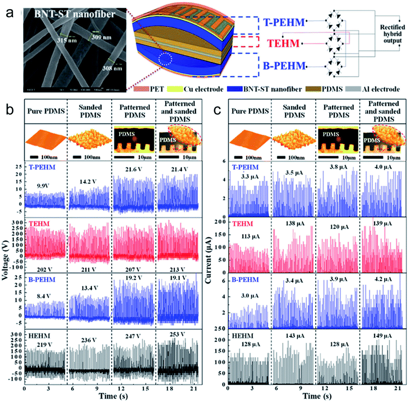 | ||
| Fig. 6 Modification of surface roughness to improve the electrical output. (a) Schematic of an all-in-one PDMS-PVDF/BNT/ST nanofibre hybrid energy harvester module structure. (b) Output voltage and (c) output current of the PTENG corresponding with the surface roughness of the PDMS layer. Reprinted with permission from ref. 49. Copyright (2020) American Chemical Society. | ||
Increasing the triboelectric charge density σ can be an effective method to enhance the triboelectric output. This can be achieved by choosing different triboelectric material pairs with a larger difference in the tribo-series or modifying the triboelectric materials to alter their surface potential. A PTENG based on nitrocellulose nanofibril paper as the triboelectric layer and BTO nanoparticle/MWCNTs@bacterial cellulose paper as the piezoelectric layer was made by Li et al.60 Wood cellulose paper was treated with HNO3 and H2SO4 to acquire the –NO3 group. In general, cellulose is slightly tribopositive in the triboelectric series because of its excess oxygen atoms and a small amount of hydroxyl groups. With the introduction of the –NO3 group, cellulose has a strong electron-withdrawing ability, which alters its triboelectric properties to tribonegative. The triboelectric and piezoelectric power densities of this hybrid generator reached 10.6 μW cm−2 and 1.21 μW cm−2, respectively, by selecting nitrocellulose and nickel as triboelectric pairs and adding a piezoelectric layer composed of BaTiO3 nanoparticles, MWCNTs, and bacterial cellulose.
A PTENG with a recombinant spider silk protein-based tribo layer and piezoelectric PVDF-enhanced PET counter layer50 was developed by Huang et al. Spider silks were genetically engineered to increase the surface potential difference from PET, so a stronger triboelectric effect was achieved. Furthermore, the PET was attached to a PVDF/graphene film so that the piezo charges generated by PVDF during the working process changed the surface potential of PET and therefore enhanced the triboelectric charge generation (Fig. 7). In this work, the TENG and PENG were integrated by a ‘self-matched’ architecture and due to the surface-potential match, the piezoelectric effect in the PENG could induce a higher triboelectric output. The device achieved a maximum power density value of 4 W m−2 which was about 100 times that of PENGs with PVDF or its composites as piezoelectric layers.
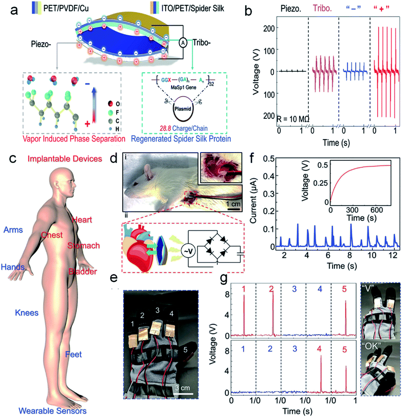 | ||
| Fig. 7 Biocompatible PTENG with PVDF/graphene decorated PET as the piezoelectric layer and recombinant spider silk coated PET/indium tin oxide (ITO) triboelectric layer. (a) Schematic of structure (b) voltage signals generated by a pure PENG, TENG and PTENG in reverse and forward connection. (c) Demonstration of the PTENG as an implantable and wearable device. (d(i)) Images of the PTENG located on a rat's heart; (ii) schematic of the energy harvesting process from the heart beats of the rat and the circuit connected to the PTENG. (e) Photo of a PTENG-based gesture monitoring glove. (f) Current generated by the PTENG implanted on the rat's heart; the inset shows the voltage–time curve of a capacitor charged by the current collected from the rat heartbeat. (g) Recorded voltage on the five fingers when making “V” and “OK” gestures. Reproduced with permission.50 Copyright 2020, John Wiley and Sons. | ||
Piezoelectric effect enhancement
The piezoelectric output can be effectively improved by increasing the piezoelectric constant of the piezo-function part, which is usually realized by adding piezoelectric nanomaterials with high piezoelectric properties to the piezoelectric functional matrix. Xiang et al. constructed a PTENG using a BTO nanoparticle (10 wt%) enhanced PVDF film and PA6 as the functional layers.51 With the introduction of BaTiO3 nanoparticles, the peak voltage increased from 384 V to 900 V and the charge density increased from 26.4 μC m−2 to 34.4 μC m−2 (Fig. 8b and c). Chowdhury et al. introduced surface modified lithium doped zinc oxide nanowires and MWCNTs into PVDF as a piezoelectric film for a PTENG.61 The surface modification was shown to improve the piezoelectric effect, because it reduced the chance of surface dielectric hindrance. The peak output voltage reached 60 V and the peak current reached 75 μA.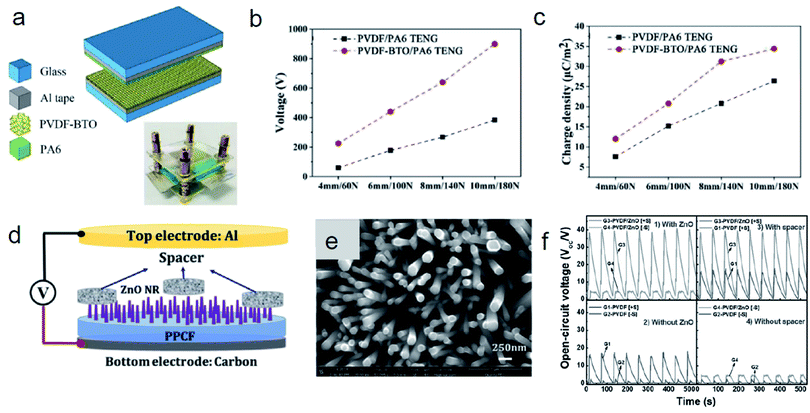 | ||
| Fig. 8 PTENGs with an enhanced piezoelectric output. (a) Schematic and photo of the BTO nanoparticle/PVDF/PA6 based PTENG. Comparisons of the output voltage (b), and charge density (c) for a PVDF/PA6 PTENG and PVDF-BTO/PA6 PTENG with different spacer distances and force. Reproduced with permission.51 Copyright 2019, John Wiley and Sons. (d) Schematic of the ZnO/PDMS/PVDF based PTENG. (e) SEM image of the ZnO nanorod arrays. (f) Comparisons of the open-circuit voltage of four types of PTENGs (G1-PVDF with a spacer, G2-PVDF without a spacer, G3-ZnO/PVDF with a spacer, G4-ZnO/PVDF without a spacer). Reproduced with permission.62 Copyright 2016, John Wiley and Sons. | ||
Zinc oxide nanorod arrays have been grown directly onto the PDMS/PVDF composite film for performance enhancement by Yang and Daoud.62 Before the growth of the ZnO nanorod array, the substrate was ultraviolet (UV) treated to enhance the hydrophilicity. The ZnO seed solution was spin-coated onto the as-prepared substrate, and the hydrothermal growth of the ZnO nanorod was followed. The generator was assembled as a two-electrode module (Fig. 8d). The comparison between the open-circuit voltages of the devices with or without ZnO nanorod arrays showed a 21.8 V enhancement, which confirms the positive role of the interfacial ZnO nanorod array in enhancing the output performance of the PTENG by increasing the effective contact area and enhancing contact electrification charges.
Nanomaterials without piezoelectric properties can also be employed to enhance the piezoelectric effect of hybrid nanogenerators. As illustrated in the work by Xue et al.',54 piezoelectric BTO nanoparticles easily became aggregated or chained in the PDMS matrix. MWCNTs with a large aspect ratio could form a long-conduction channel and introduce a bridging effect between the BaTiO3 chains or aggregates. Thus, the electrical conductivity of the piezoelectric substrate was enhanced so that some of the internal piezoelectric charges could be transferred to the surface of the material, improving the electrostatic induction on the surface of the material. As a result, the increased piezoelectric output is achieved.
Yang and Daoud carried out analysis of synergetic effects in a composite-based flexible hybrid generator.63 The device was fabricated with the two-electrode module, and the test results are presented in Fig. 9. The open-circuit voltage and short-circuit current of PVDF/BTO nanoparticle samples without CNTs are 16.67 V and 0.76 mA m−2, and 19.26 V and 0.85 mA m−2, respectively. With the addition of CNTs, these properties increased to 23.94 V and 1.19 mA m−2, and 25.77 V and 1.28 mA m−2. The spacer could distinguish the triboelectric and piezoelectric potentials and act as a ‘charge splitter’ during the operation of the hybrid NG. As can be seen in Fig. 9c and d, the group with the spacer yielded a much higher electrical output than the PENG with individual effects made from the same materials.
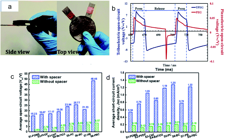 | ||
| Fig. 9 A flexible PTENG based on polymer/nanofiller and polymer/hybrid nanofiller composites. (a) Side and top views of the hybrid generator. (b) Triboelectric and piezoelectric voltage behavior in one working cycle. (c and d) Open-circuit voltage and short-circuit current of 8 types of generators (functional layer: S1-pure PDMS, S2-pure PVDF, S3-PDMS with CNT, S4-PDMS with BaTiO3, S5-PVDF with CNT, S6-PDMS with BaTiO3 and CNT, S7-PVDF with BaTiO3, S8-PVDF with BaTiO3 and CNT) when working with and without a spacer. Reproduced from ref. 63 with permission from the Royal Society of Chemistry. | ||
It has been proved that conductive materials such as Ag64 and graphene65 have similar effects to CNTs on the enhancement of piezoelectric performance. These conductive fillers facilitate a more efficient transfer of internal piezoelectric charges to the surface, generating more induced charges on the electrode and increasing the output signal. A typical example is shown in the work by Sriphan et al.,52 where the synergistic effect of adding additional piezoelectric and conductive materials on the PTENG output was studied. In their PDMS composite based PTENG, BTO nanoparticles are the primary piezoelectric ceramic material, Ag nanoparticles improve the conductivity, and Ti0.8O2 nanosheets were used as the secondary piezoelectric material. The electrical testing results confirmed that a small amount of additional piezoelectric ceramics and conductive materials produced more electric dipoles in the composite film, leading to a higher electric output. Specifically, 0.3 vol% of Ti0.8O2 nanosheets and 1.5 vol% of Ag nanoparticles showed the optimum modifying results with the output voltage and current density reaching 150 V and 0.32 μA cm−2, respectively, which are 60 and 32 times higher than that of neat PDMS-based energy harvesting materials. When the doping ratio of Ti0.8O2 nanosheets reached 0.5 vol%, a higher level of agglomeration of BTO and Ti0.8O2 nanofillers was caused, resulting in a decrease in the generated electrical output.
Applications of hybrid PTENGs
To meet the ever-increasing demand in energy supply, hybrid PTENGs can be conveniently applied as sustainable resources for various purposes, when the waste energy occurs as periodic kinetic energy, whether it is from the movement of waves or wind, or human body motion. Flexible hybrid PTENGs provide direct and active linkage/triggering of the electrical output signals upon external mechanical deformation, and have strong potential for the utilization in self-powered sensors, intelligent human–machine interactions, and energy harvesting devices even for ocean environments (Table 4).66 The fabrication of PTENGs is generally simple and cost effective and can be easily applied for large-scale productions. Simultaneously, they offer excellent durability and stability, which can be further integrated into the design of smarter and more sophisticated electronic devices.| Capabilities and applications | Triboelectric constitutes | Piezoelectric constitutes | Sensitivity | Output voltage | Output power | Ref. |
|---|---|---|---|---|---|---|
| Monitor vital signs such as respiration and pulse | PDMS & skin | PVDF-TrFE nanofibres | 7.84 V N−1 (TENG) | — | 84 μW cm−2 (TENG) | 55 |
| Detect body motion | 1.42 V N−1 (PENG) | 0.11 μW cm−2 (PENG) | ||||
| Detect body motion | Silk/PEO nanofibres | PVDF nanofibres | — | 500 V | 310 μW cm−2 | 67 |
| Send alarms to remote terminals | ||||||
| Monitor acceleration and brake | Eco flex & nickel fabric | PZT | 15 V g−1 (TENG) | — | 6.5 mW (PENG) | 68 |
| Send acceleration signals to remote terminals | ||||||
| Monitor motion type | PDMS film | PZT nanofibres/PVDF-TrFE nanofibres | 15.43 V kPa−1 (0–100 kPa) | — | — | 69 |
| Monitor pulse | 18.96 V kPa−1 (100–800 kPa) | |||||
| Detect vibration and acceleration | Silicone rubber, micropatterned | PVDF film | 3.65 μW g−1 (amplitude 3 mm) | 25.8 V | 55 | |
| 6.14 μW g−1 (amplitude 6 mm) | ||||||
| Harvest walking, running and jumping energy | Poly(3,4-ethylenedioxythiophene) (PEDOT) polystyrenesulfonate (PSS) coated fabric | PZT chip | 0.228 V N−1 | — | 1.71 mW | 70 |
| Detect foot pressure | ||||||
| Convert low frequency rotation energy to electricity | Steel & PTFE | PVDF | — | 51.6 V | 1.04 W | 71 |
| Power small electronic devices | PDMS & Ag nanoparticles | BTO nanoparticles & Ti0.8O2 nanosheets (dispersant) | — | 150 V | 48 μW cm−2 | 52 |
| Power small electronic devices | PET-ITO & Cu-Kapton | PVDF-TrFE nanofibres | — | 96 V (PENG) | 22.18 μW (PENG) | 72 |
| Harvest water wave energy | Kapton & PDMS | 88 V (upper TENG) | 28.67 μW (upper TENG) | |||
| 361.27 V (lower TENG) | 441 μW (lower TENG) | |||||
| Harvest wind energy in a broad wind speed range | Fluorinated ethylene propylene(FEP) & polyimide& Al | 0.67Pb(Mg1/3Nb2/3)O3–0.33PbTiO3 nanofibres | — | 216 V | 0.24 mW | 73 |
Self-powered sensors
One of the applications of hybrid nanogenerators is in sensors for bio-detection. By selecting biocompatible flexible materials, hybrid nanogenerators can be developed and attached to different parts of the human body such as the wrist, neck, and joints, which can convert the pulse, swallowing, and joint movements into electrical signals. Collecting and processing these signals and connecting them to medical systems can help in reducing the risk of cardiac arrest, choking in the trachea, or joint diseases, by allowing their real-time monitoring.55Instead of directly attaching to the human body, flexible PTENGs can also be integrated into fabrics and clothing. Guo et al. prepared a PTENG based on electrospun PVDF nanofibres that can be sewn onto clothes and trousers to respond to vibration and shock.67 In their work, once a micro signal generator was connected to the PTENG and the voltage output exceeded a set threshold, the signal generator could send an emergency signal to a terminal through their designed network. In other applications, real-time responses can be used for monitoring falls and other accidents for health care. By considering the amplitude of the signal, PTENGs can then be used as gesture sensors for disease diagnosis, physical therapy and health monitoring.74 The energy scavenged from the body movement can also be converted into electricity and stored to supply power for these wearable sensors.75Fig. 10 shows recent examples of PTENGs based on biopolymer chitosan with high output performance and textile hybrid PTENGs with moisture management capability for wearing comfort. By adopting three enhancement strategies, i.e. addition and dispersion of lead-free piezoelectric nanorods (BTO nanorods), using soft electrodes based on bacterial cellulose/CNT composites, and using a self-charge pumping module, the electrical outputs of the PTENG based on chitosan/BTO nanorod composite (Fig. 10a) realized an open-circuit voltage of 247.2 V, current density of 36.7 μA cm−2, and peak power density of 1568 μW cm−2 (Fig. 10b and c), respectively.37 The power output increased 4 times over that of neat chitosan TENGs. As shown in Fig. 10d, the powerful nanogenerator successfully lit 100 LED lights and drove 7-segments. For wearable electronics, textile PTENGs based on electrospun PVDF-TrFE nanofibres exhibited a peak power density of 5.2 W m−2 at low frequency movement as well as outstanding thermal-moisture management capability (Fig. 10e).76 These e-textiles have demonstrated to be conveniently embedded into shoe insole or sewn into clothing to power minute electronic devices for motion sensing (Fig. 10f–j).
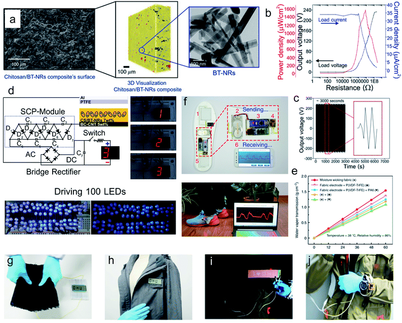 | ||
| Fig. 10 Flexible PTENGs with high output performance and comfortability for physiological signal monitoring. (a) Morphology of the chitosan/BTO nanorod composite (SEM image of the surface, 3D visualization, and the TEM image of nanorods); (b) high output power and voltage; (c) output voltage stability; (d) driving 100 LEDs and 7-segments. Reproduced with permission.37 Copyright 2021, Elsevier. (e) Textile PTENG with moisture transmission properties; (f) self-powered gesture sensor printed on shoe insoles for capturing gait while transmitting to a computer in situ; E-textile (g) sewn into fabrics; (h) sewn into clothes to power LCDs; (i and j) sewn onto the surface of clothes to drive digital electroluminescent lattices and watches by scavenging energy from the shoulder movement. Open access under a Creative Commons Attribution 4.0 International License.76 | ||
PTENGs can also be used as self-powered accelerators for various applications such as harsh environment monitoring and wireless sensor nodes. For instance, Wang et al. developed a PZT piezoelectric bimorph that was sandwiched between two TENGs.68 The TENG parts of the device could respond to vibration corresponding with the attached equipment acceleration, thus generating a triboelectric signal to reflect the acceleration direction and strength. Here the PENG part was connected to the microcontroller unit and radiofrequency transceiver to supply energy so that the triboelectric signal could be sent to a remote terminal to realize remote monitoring. This device showed potential for various machine/robot monitoring applications in harsh environments and remote areas by revealing vibration incidents when unusual acceleration values were found. Due to their high sensitivity to vibration, PTENGs can be made into a self-driving sound recording device or used for detecting the sound volume and tackle noise issues.77,78 A PTENG vibration sensor can also be placed on vehicles or lathes, which generate mechanical vibrations, to monitor whether the engine of the vehicle and the rotating shaft of the lathe are working normally, and avoid the danger and loss caused by abnormal vibration. Hybrid PTENGs can also be combined with self-powered gas sensors for hazardous gas detection in harsh environments such as mining sites, chemical factories and industrial tunnels.79
Energy harvesters at different scales
Because of the power output limitation, most single PTENGs are designed to harvest micromechanical energy for powering small and portable electronics rather than large instruments. For this end use, PDMS, PVDF, PTFE, and other biocompatible, flexible materials are usually used as the substrate, filled with BTO, KNN, ZnO and other piezoelectric ceramic nanomaterials to prepare functional films or fibres, and are then combined with flexible electrodes such as conductive organic compounds, and conductive fabrics to fabricate wearable devices.40,80,81 When PTENGs are used for collecting the redundant mechanical energy generated by the human body to supply energy, e.g. for small wearable devices, such minute devices can be integrated with insoles, socks, gloves, pants, or patches that can be attached to flexible surfaces.70,82 Using current technologies, these wearable PTENGs can produce enough power to drive certain small sensors or charge mobile phones slowly.22What's more, hybrid PTENGs can even be utilized to harvest environmental mechanical energy such as ocean waves and raindrops for self-powered navigation.83 Chen et al. fabricated a PTENG with a wavy structure, where compliant PVDF-TrFE nanofibres were used as the middle piezoelectric layer; Cu-Kapton was paired with PDMS and PET to form the lower and upper wavy shape triboelectric layers.72 The wavy structure was self-recoverable due to the flexibility and elasticity of PET, PDMS, and Kapton. These merits make the hybrid nanogenerator more effective in collecting low-frequency mechanical energy with a small amplitude, granting them adaptability for collecting water wave energy, tidal energy, and other types of energy that are difficult to harness using traditional generators.83Fig. 11 shows the various structural designs of PTENGs for energy harvesting. Fig. 11a–c present a butterfly wing structure of a multiunit arc-shaped PTENG device that produces current density as high as 2500 mA m−2, mainly resulting from the high surface charge density from the synergistic effect of triboelectric PDMS and Al layers and the piezoelectric 0.3Ba0.7Ca0.3TiO3–0.7BaSn0.12Ti0.88O3 (0.3BCT–0.7BST) nanoparticles. Fig. 11d and e show an example of combining a bimorph-based PENG and TENG for efficient rotation-energy collection. The high electrical outputs have shown to be stable and independent of the rotation rate. This uniquely structured PTENG has potential to power electronics in a sustainable manner. Fig. 11f–h show an example of a hybrid PTENG composed of a compressive mode PENG and a TENG to effectively harvest vibration energy at low frequency excitation. The impact type electric generator exhibited a high power output and a broad operational bandwidth, which facilitates operation in real environments where the frequency varies making the PTENG more adaptable.
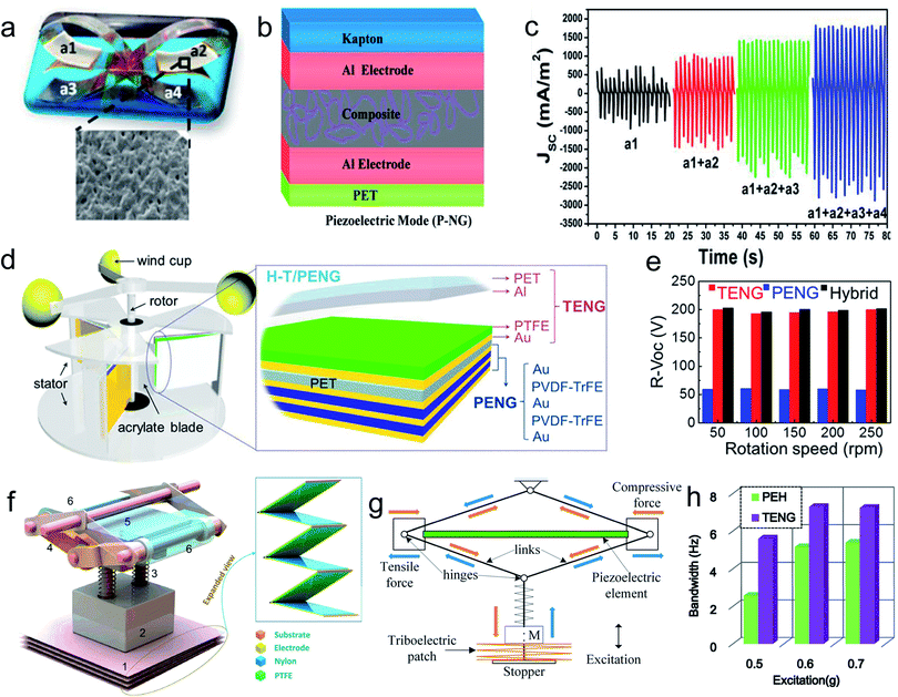 | ||
| Fig. 11 PTENG energy harvesters with various structural designs. (a) Butterfly wing structure composed of four arc-shaped hybrid nanogenerators with an irregular surface morphology (a1, a2, a3, and a4); (b) schematic diagram of PTENG lay-up; (c) output current density of single (a1) and multiunit hybrid nanogenerators connected in parallel at a constant acceleration speed of 1 m s−2. Reproduced with permission.84 Copyright 2018, American Chemical Society. (d) Schematic diagram of a PTENG mounted in a custom-built frame for rotational energy harvesting. The PTENG constituting layers are shown in the inset; (e) the rectified open-circuit voltage of a TENG, PENG and PTENG produced at different rotation speeds. Reproduced with permission.85 Copyright 2019, Elsevier. (f) Structural design of a PTENG for vibration energy harvesting consisting of a spring-mass system; (g) loading condition of the NG; (h) bandwidth of the piezoelectric energy harvester (PEH) and the TENG. Reproduced with permission.86 Copyright 2018 Elsevier. | ||
Fig. 12 shows a number of application examples where PTENGs are used for self-powered sensors and energy harvesting at different scales. Fig. 12a–c show an example of utilizing PTENG to convert walking or running energy to electricity in order to light up LEDs embedded in shoe soles and to sense foot pressure through wireless transmission.75 In this work multiple hybrid PTENGs were made to sense different pressure points at forefoot, heel and arch locations. Wang et al. proposed a synergetic piezoelectric and triboelectric mechanism for wind energy harvesting.73 In their wind driven PTENG module (Fig. 12d and e), the piezoelectric part worked in the vibration area and started to function at low wind speeds, whereas the triboelectric part worked at the vibration boundaries and cooperated with the piezoelectric part at high wind speeds. The vibration of the cantilever in the middle of the generator was caused by the wind, and the cantilever came into contact with or separated from the triboelectric layers on both sides to generate triboelectricity. Different from traditional wind turbines, this PTENG wind harvester could generate electricity at both high and low wind speeds. Moreover, these units offer the advantages of small volume, low cost, and easy maintenance. Wang et al. recently demonstrated a virtual reality train monitoring system using a self-powered wireless sensing node constructed from hybrid PTENGs in harsh environments.87 The transmitted acceleration signals were sent wirelessly presenting diverse potentials for IoT applications (Fig. 12f). The grids of PTENGs showed energy conversion efficiency as high as 30.22% for harvesting large scale water wave energy that is suitable for powering self-sustainable coastal wireless sensors (Fig. 12g and h).88
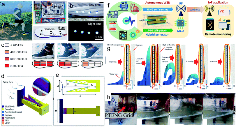 | ||
| Fig. 12 Application of PTENGs at different scales. (a–c) PTENG powered LEDs in the shoe at different times of the day and foot pressure monitoring. (a) Self-powered lightning by walking and running; (b) LED embedded sole; (c) wireless foot pressure sensing. Reproduced with permission.75 Copyright 2020, Elsevier. (d and e) Hybrid nanogenerator for small scale wind energy harvesting. (d) Cantilever device structure with various functional layers; (e) geometric configuration. Reproduced from ref. 73 with the permission of AIP Publishing. (f) Illustration graph of wireless sensing of equipment vibration by a PTENG. Reproduced with permission.87 Copyright 2021, Elsevier. (g and h) Grid of PTENGs to harvest wave impact energy. (g) PTENG working mechanism under wave impact; (h) photos of the PTENG grid located on the wave tank wall before water impact, contacted and pressed, contacted and released, and releasing (from left to right). Reproduced with permission.88 Copyright 2020, Elsevier. | ||
Challenges for future development of hybrid PTENGs and conclusion
All in all, hybrid PTENGs that combine piezoelectric and triboelectric mechanisms can increase energy scavenging and conversion efficiency beyond the linear summation of separate piezoelectric and triboelectric generators. By the rational design of the nano- and micro-structures and polarization directions, both mechanical deformation and contact friction of materials can be utilized simultaneously for energy scavenging.There are still many challenges for the further development of hybrid PTENGs for their broader uses in practical applications. Power generation from nanogenerators is still low due to the low biomechanical energy and the small frequency of mechanical movement. Triboelectricity produces a high output voltage but low output current; sometimes the voltage can even be high enough to produce an arc between the two triboelectric layers, resulting in leakage, further reducing the nanogenerator power output.
It is imperative to continuously investigate the enhancement of the PTENG power output performance based on the coupling mechanisms between piezoelectric and triboelectric effects. Nanofillers such as lead-free inorganic compounds (e.g. BTO and KNN), metallic nanofillers, carbon nanofillers, and ionic salts are effective nucleating fillers to induce polar electroactive phases, with no requirement for electrical polarization, to achieve a higher piezoelectric effect and dielectric properties that facilitate electrical performance. These nanofillers are also able to increase the stretchability, flexibility and robustness of the fabricated nanogenerators.18 With the introduction of these nanofillers, parameters such as charge transport, distribution in the polymer matrices and breakdown fields are significantly influenced, e.g. the breakdown strength of polymer/conductive filler nanocomposites can be modulated because of the high conductivity of nanofillers that can reversely alter the piezoelectricity. Strategies such as alignment of conductive fillers along with the perpendicular direction of the electric field can be implemented to improve the performance of PTENGs.89 Further electrical polarization either by contact or non-contact modes (applying a corona discharge close to the specimens)/ionized air injection can also improve the electroactive phase content and enhance nanogenerator performance. Since the triboelectric effect is basically a surface charging process, to modify the tribosurface structure and morphology with micro- and nano-structure patterns (multiscale patterns,90 and nanofeature surfaces such as pyramid patterns) can increase the roughness and effective friction area, resulting in an enhanced triboelectric effect and electrical outputs. Apart from surface structural variations, materials characteristics such as electron affinity and the work function also strongly affect the output performance.
In view of the potential applications of PTENGs as sensors in physiological monitoring and medical treatment, sensing sensitivity needs to be further honed towards self-powered sensors based on minute physiological signs such as heart beats, intestinal movement, and respiratory rates. Self-powered sensors are usually able to realize either a broad testing range or high sensitivity. For example, some of these sensors can offer high sensitivity when sensing human pulse waveforms but cannot accurately detect human motion since they have poor linearity (many of them are only useful for giving binary information) and a limited sensing range.91 By using smart new material choices and a well-optimized compliant structure of hybrid PTENGs, the sensing intensity and relaxation time can be controlled and the sensitivity and accuracy can be improved to realize broad sensing ranges, better sensitivity and also wearing comfort. The capability to detect changes in pressure, motion and temperature provides wider uses for monitoring pulse, breathing and body temperature and also expands applications in medical treatment and athletic training.
Stability and durability are important factors in developing both self-powered sensors and energy harvesters. Under repetitive mechanical loading or strong chemical treatments, significant reduction in the electrical performance of PTENGs may occur due to the worn or destroyed surficial morphological micro/nano structures.92 In real applications, PTENGs may be affected by various environmental factors such as humidity, dryness, high and low temperature, radiation, and adsorbed substances from surroundings, which are all distant from the reasonably controlled laboratory conditions. For instance, the contact electrification process for generating triboelectricity can be highly influenced by water absorption since water can fill the nano gaps or form as thin layers on surfaces during the operation, which strongly deteriorate the output performance, stability and durability of nanogenerators. Humidity can result in reduction in the dielectric strength of piezoelectric materials that affect ion and defect mobilities between grain boundaries and electrode materials. This further causes device failure due to increased power consumption as a result of the leaked current. Additional proposed causes for degraded performance from water include increased surface conduction, structural assimilation of interstitial atomic hydrogen and replaced oxygen vacancies through ceramics.93 The negative influence of high temperature on piezoelectric properties is mainly because a ferroelectric material loses polarization above the Curie temperature; the triboelectric effect is also limited by temperature due to the electron thermion emission.94 UV radiation affects electrical performance by desorbing oxygen molecules and therefore leads to a reduced piezoelectric effect. Contaminants such as absorbed substances change the resistance of functional materials and vary the leakage current of piezoelectric materials and influence the device performance.
More research is required in this aspect since being able to function outside of controlled environments is a prerequisite for long term sensing in a wide range of applications from those for home appliances to sophisticated outer space gadgets. High quality packaging with special sealing techniques can be a way of solving this issue; however, such approaches will undoubtfully increase the complexity and fabrication cost. Hydrophobic surfaces are preferable since it is more difficult for water or moisture to transfer through them. PTENGs have similar issues to TENGs as they also need contact separation or sliding motion that cause damage by long term cyclic movements. Therefore, low durability affects the practical use of PTENGs for continuous health monitoring and needs to be addressed.
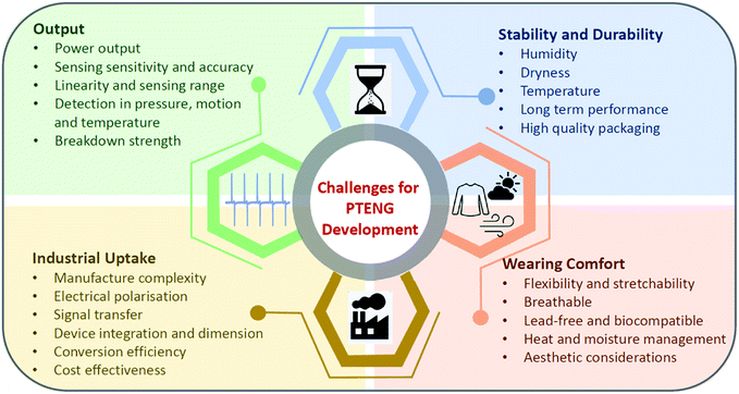
In addition to physiological monitoring of human activities, hybrid PTENGs have been manufactured into flapping-blade devices to harvest wind energy.95 In such devices, the flexible piezoelectric cantilever converts wind energy to an electrical output and the flapping blades, attached with the cantilever, make contact with double frames at each side to amplify the vibration and friction, showing good performance in terms of power density at low wind speeds. Such energy harvesting systems should be further explored for industrial uptake. PTENG has also been made into self-charging energy storage packages to combine hybrid nanogenerators with electrochromic micro-supercapacitors, which can also show charging in real-time.26 However, these intelligent systems require significant improvement in their conversion efficiency. Altogether, hybrid PTENGs have also been shown to harvest rotation mechanical energy effectively through movements from human activity, vehicles, wind, and waves.85 All these features demonstrate that hybrid PTENGs are effective sustainable power resources that can contribute to both large energy harvesting platforms that can play an important role against the greenhouse effect, global warming and small digital healthcare devices for self-powered sensors for healthcare and sport training, and solving the issue of decentralized IoT devices in the future. This will further lead to three main trends in the outlook of smart cities through mass urbanization by incorporating intelligent devices, self-powered bioelectronics for personalized healthcare, and exploration of renewable energies for climate change and energy crisis mitigations.96 The challenges for future development of PTENGs are summarized in Fig. 13.
The fast-evolving information age requires highly efficient energy supply and wide ranges of solutions to power diverse intelligent devices and technologies for sensing, monitoring, interacting, and recognizing and learning. While large scale installation of sensors poses great challenges, hybrid piezo–triboelectric nanogenerators are low-cost, and accessible, enabling infrastructure for big data and artificial intelligence. PTENGs can be potentially applied in diverse areas such as intelligent sports, artificial sensory nervous systems, intelligent signal recognition, security systems and document management systems, etc.97 For example, PTENG technology can bring many opportunities for intelligent athlete training and competition. Large amounts of distributed self-powered sensors and smart devices can be connected into a network that is able to measure movements of athletes and record exercise habits for future improvement in performance, with the facilitation from big data analysis and cloud computing.98 In addition, artificial intelligence (AI) can assist with designing and improving the performance of PTENGs depending on the application requirements.99 For the proliferation of self-powered sensors in large scale deployment, the cost of the current energy harvesting solutions needs to be reduced several orders of magnitude.97
In this review, we have analyzed the basic working principles, micro and nano-structure designs, manufacturing processes, performance enhancements, and applications of hybrid PTENGs. Combing the characteristics of piezoelectric materials and triboelectric generators, PTENGs offer a higher efficiency and broader energy collection frequency band than either piezoelectric and triboelectric systems. Due to the coupling effect, the electrical output of PTENGs is more than the simple addition of the triboelectric and the piezoelectric parts, stemming from the synergistic enhancement between the two mechanisms. PTENGs also have a versatile designing architecture to meet different practical needs. Innovative electrode structures should be used to simplify production complexity, ease signal transfer and reduce device dimensions. Further challenges such as improvement of stability and durability remain to achieve broader practical applications. New materials, designs and optimization approaches are required to address these challenges so that PTENGs can be envisioned for physiological monitoring, health care, transportation, marine energy, and smart city applications.
Conflicts of interest
There are no conflicts to declare.References
- Y. Hu and Z. L. Wang, Nano Energy, 2015, 14, 3–14 CrossRef CAS
.
- W. Paosangthong, R. Torah and S. Beeby, Nano Energy, 2019, 55, 401–423 CrossRef CAS
.
- P. Glynne-Jones, S. P. Beeby and N. M. White, IEE Proc.: Sci., Meas. Technol., 2001, 148, 68–72 CrossRef
.
- Z. L. Wang and J. Song, Science, 2006, 312, 242–246 CrossRef CAS PubMed
.
- F.-R. Fan, Z.-Q. Tian and Z. Lin Wang, Nano Energy, 2012, 1, 328–334 CrossRef CAS
.
- G. Zhu, Z. H. Lin, Q. Jing, P. Bai, C. Pan, Y. Yang, Y. Zhou and Z. L. Wang, Nano Lett., 2013, 13, 847–853 CrossRef CAS
.
- S. R. Anton and H. A. Sodano, Smart Mater. Struct., 2007, 16, R1–R21 CrossRef CAS
.
- X. Guan, B. Xu and J. Gong, Nano Energy, 2020, 70, 104516 CrossRef CAS
.
- J. Xing, H. Chen, L. Jiang, C. Zhao, Z. Tan, Y. Huang, B. Wu, Q. Chen, D. Xiao and J. Zhu, Nano Energy, 2021, 84, 105900 CrossRef CAS
.
- X. Guan, H. Chen, H. Xia, Y. Fu, J. Yao and Q.-Q. Ni, Composites, Part B, 2020, 197, 108169 CrossRef CAS
.
- M. A. Johar, A. Waseem, M. A. Hassan, I. V. Bagal, A. Abdullah, J.-S. Ha and S.-W. Ryu, Adv. Energy Mater., 2020, 10, 2002608 CrossRef CAS
.
- N.-J. Ku, G. Liu, C.-H. Wang, K. Gupta, W.-S. Liao, D. Ban and C.-P. Liu, Nanoscale, 2017, 9, 14039–14046 RSC
.
- H. Khan, N. Mahmood, A. Zavabeti, A. Elbourne, M. A. Rahman, B. Y. Zhang, V. Krishnamurthi, P. Atkin, M. B. Ghasemian, J. Yang, G. Zheng, A. R. Ravindran, S. Walia, L. Wang, S. P. Russo, T. Daeneke, Y. Li and K. Kalantar-Zadeh, Nat. Commun., 2020, 11, 3449 CrossRef CAS
.
- X. Song, F. Hui, K. Gilmore, B. Wang, G. Jing, Z. Fan, E. Grustan-Gutierrez, Y. Shi, L. Lombardi, S. A. Hodge, A. C. Ferrari and M. Lanza, Nanoscale, 2017, 9, 6237–6245 RSC
.
- Z. L. Wang, ACS Nano, 2013, 7, 9533 CrossRef CAS PubMed
.
- Q. Jiang, B. Chen, K. Zhang and Y. Yang, ACS Appl. Mater. Interfaces, 2017, 9, 43716–43723 CrossRef CAS
.
- X. Peng, K. Dong, C. Ye, Y. Jiang, S. Zhai, R. Cheng, D. Liu, X. Gao, J. Wang and Z. L. Wang, Sci. Adv., 2020, 6, eaba9624 CrossRef CAS
.
- J. Zhang, D. Liu, Q. Han, L. Jiang, H. Shao, B. Tang, W. Lei, T. Lin and C. H. Wang, Composites, Part B, 2019, 175, 107157 CrossRef CAS
.
- G. Khandelwal, A. Chandrasekhar, N. P. Maria Joseph Raj and S.-J. Kim, Adv. Energy Mater., 2019, 9, 1803581 CrossRef
.
- L. Lan, T. Yin, C. Jiang, X. Li, Y. Yao, Z. Wang, S. Qu, Z. Ye, J. Ping and Y. Ying, Nano Energy, 2019, 62, 319–328 CrossRef CAS
.
- Y. Liu, J. Ping and Y. Ying, Adv. Funct. Mater., 2021, 31, 2009994 CrossRef CAS
.
- S. Chandrasekaran, C. Bowen, J. Roscow, Y. Zhang, D. K. Dang, E. J. Kim, R. D. K. Misra, L. Deng, J. S. Chung and S. H. Hur, Phys. Rep., 2019, 792, 1–33 CrossRef CAS
.
- X. Feng, H. Zou, H. Xiang, X. Guo, T. Zhou, Y. Wu, W. Xu, P. Yan, C. Wang, J. G. Zhang and Y. Yu, ACS Appl. Mater. Interfaces, 2016, 8, 16718–16726 CrossRef CAS
.
- Y.-K. Fuh, S.-C. Li and C.-Y. Chen, APL Mater., 2017, 5, 074202 CrossRef
.
- J. Chen, H. Guo, X. He, G. Liu, Y. Xi, H. Shi and C. Hu, ACS Appl. Mater. Interfaces, 2016, 8, 736–744 CrossRef CAS PubMed
.
- S. Qin, Q. Zhang, X. Yang, M. Liu, Q. Sun and Z. L. Wang, Adv. Energy Mater., 2018, 8, 1800069 CrossRef
.
- J. He, S. Qian, X. Niu, N. Zhang, J. Qian, X. Hou, J. Mu, W. Geng and X. Chou, Nano Energy, 2019, 64, 103933 CrossRef CAS
.
- J. Song, B. Yang, W. Zeng, Z. Peng, S. Lin, J. Li and X. Tao, Adv. Mater. Technol., 2018, 3, 1800016 CrossRef
.
- S. Chen, X. Tao, W. Zeng, B. Yang and S. Shang, Adv. Energy Mater., 2017, 7, 1601569 CrossRef
.
- P. Sahatiya, S. Kannan and S. Badhulika, Applied Materials Today, 2018, 13, 91–99 CrossRef
.
- D. W. Lee, D. G. Jeong, J. H. Kim, H. S. Kim, G. Murillo, G.-H. Lee, H.-C. Song and J. H. Jung, Nano Energy, 2020, 76, 105066 CrossRef CAS
.
- W. S. Jung, M. G. Kang, H. G. Moon, S. H. Baek, S. J. Yoon, Z. L. Wang, S. W. Kim and C. Y. Kang, Sci. Rep., 2015, 5, 9309 CrossRef CAS PubMed
.
- H. H. Singh and N. Khare, Nano Energy, 2018, 51, 216–222 CrossRef CAS
.
- Q. Zhu, L. Dong, J. Zhang, K. Xu, Y. Zhang, H. Shi, H. Lu, Y. Wu, H. Zheng and Z. Wang, Ceram. Int., 2020, 46, 28277–28284 CrossRef CAS
.
- G. Suo, Y. Yu, Z. Zhang, S. Wang, P. Zhao, J. Li and X. Wang, ACS Appl. Mater. Interfaces, 2016, 8, 34335–34341 CrossRef CAS PubMed
.
- Y. Qian and D. J. Kang, ACS Appl. Mater. Interfaces, 2018, 10, 32281–32288 CrossRef CAS
.
- S. Pongampai, T. Charoonsuk, N. Pinpru, P. Pulphol, W. Vittayakorn, P. Pakawanit and N. Vittayakorn, Composites, Part B, 2021, 208, 108602 CrossRef CAS
.
- T. Huang, C. Wang, H. Yu, H. Wang, Q. Zhang and M. Zhu, Nano Energy, 2015, 14, 226–235 CrossRef CAS
.
- D. H. Kim, B. Dudem and J. S. Yu, ACS Sustainable Chem. Eng., 2018, 6, 8525–8535 CrossRef CAS
.
- H. Patnam, B. Dudem, N. R. Alluri, A. R. Mule, S. A. Graham, S.-J. Kim and J. S. Yu, Compos. Sci. Technol., 2020, 188, 107963 CrossRef CAS
.
- M. Sahu, V. Vivekananthan, S. Hajra, D. K. Khatua and S.-J. Kim, Applied Materials Today, 2021, 22, 100900 CrossRef
.
- Y. Wu, J. Qu, W. A. Daoud, L. Wang and T. Qi, J. Mater. Chem. A, 2019, 7, 13347–13355 RSC
.
- W. Wang, J. Zhang, Y. Zhang, F. Chen, H. Wang, M. Wu, H. Li, Q. Zhu, H. Zheng and R. Zhang, Appl. Phys. Lett., 2020, 116, 023901 CrossRef
.
- G. Hassan, F. Khan, A. Hassan, S. Ali, J. Bae and C. H. Lee, Nanotechnology, 2017, 28, 175402 CrossRef PubMed
.
- X.-S. Z. Mengdi Han, B. Meng, W. Liu, W. Tang, X. Sun, W. Wang and H. Zhang, ACS Nano, 2013, 7, 8554–8560 CrossRef PubMed
.
- S. Cheon, H. Kang, H. Kim, Y. Son, J. Y. Lee, H.-J. Shin, S.-W. Kim and J. H. Cho, Adv. Funct. Mater., 2018, 28, 1703778 CrossRef
.
- Y. M. Yousry, K. Yao, A. M. Mohamed, W. H. Liew, S. Chen and S. Ramakrishna, Adv. Funct. Mater., 2020, 30, 1910592 CrossRef CAS
.
- A. A. Narasimulu, P. Zhao, N. Soin, K. Prashanthi, P. Ding, J. Chen, S. Dong, L. Chen, E. Zhou, C. D. Montemagno and J. Luo, Nano Energy, 2017, 40, 471–480 CrossRef CAS
.
- S. H. Ji, W. Lee and J. S. Yun, ACS Appl. Mater. Interfaces, 2020, 12, 18609–18616 CrossRef CAS
.
- T. Huang, Y. Zhang, P. He, G. Wang, X. Xia, G. Ding and T. H. Tao, Adv. Mater., 2020, 32, e1907336 CrossRef PubMed
.
- X. Tao, H. Jin, M. Ma, L. Quan, J. Chen, S. Dong, H. Zhang, C. Lv, Y. Fu and J. Luo, Phys. Status Solidi A, 2019, 216, 1900068 CrossRef
.
- S. Sriphan, T. Charoonsuk, T. Maluangnont and N. Vittayakorn, ACS Appl. Energy Mater., 2019, 2, 3840–3850 CrossRef CAS
.
- S. Niu and Z. L. Wang, Nano Energy, 2015, 14, 161–192 CrossRef CAS
.
- C. Xue, J. Li, Q. Zhang, Z. Zhang, Z. Hai, L. Gao, R. Feng, J. Tang, J. Liu, W. Zhang and D. Sun, Nanomaterials, 2014, 5, 36–46 CrossRef PubMed
.
- J. Zhu, X. Hou, X. Niu, X. Guo, J. Zhang, J. He, T. Guo, X. Chou, C. Xue and W. Zhang, Sens. Actuators, A, 2017, 263, 317–325 CrossRef CAS
.
-
J. Zhang, M. Shi, H. Chen, M. Han, Y. Song, X. Cheng and H. Zhang, presented in part at the 2016 IEEE 29th International Conference on Micro Electro Mechanical Systems (MEMS), 2016, pp. 173–176 Search PubMed
.
- S. C. Mannsfeld, B. C. Tee, R. M. Stoltenberg, C. V. Chen, S. Barman, B. V. Muir, A. N. Sokolov, C. Reese and Z. Bao, Nat. Mater., 2010, 9, 859–864 CrossRef CAS PubMed
.
- A. Yu, Y. Zhu, W. Wang and J. Zhai, Adv. Funct. Mater., 2019, 29, 1900098 CrossRef CAS
.
- Y. Zou, J. Xu, K. Chen and J. Chen, Adv. Mater. Technol., 2021, 6, 2000916 CrossRef CAS
.
- M. Li, Y. Jie, L.-H. Shao, Y. Guo, X. Cao, N. Wang and Z. L. Wang, Nano Res., 2019, 12, 1831–1835 CrossRef CAS
.
- A. R. Chowdhury, A. M. Abdullah, I. Hussain, J. Lopez, D. Cantu, S. K. Gupta, Y. Mao, S. Danti and M. J. Uddin, Nano Energy, 2019, 61, 327–336 CrossRef CAS
.
- X. Yang and W. A. Daoud, Adv. Funct. Mater., 2016, 26, 8194–8201 CrossRef CAS
.
- X. Yang and W. A. Daoud, J. Mater. Chem. A, 2017, 5, 9113–9121 RSC
.
- B. Dudem, D. H. Kim, L. K. Bharat and J. S. Yu, Appl. Energy, 2018, 230, 865–874 CrossRef CAS
.
- M. M. Abolhasani, K. Shirvanimoghaddam and M. Naebe, Compos. Sci. Technol., 2017, 138, 49–56 CrossRef CAS
.
- J. Yu, X. Yang and Q. Sun, Advanced Intelligent Systems, 2020, 2, 1900175 CrossRef
.
- Y. Guo, X.-S. Zhang, Y. Wang, W. Gong, Q. Zhang, H. Wang and J. Brugger, Nano Energy, 2018, 48, 152–160 CrossRef CAS
.
- L. Wang, T. He, Z. Zhang, L. Zhao, C. Lee, G. Luo, Q. Mao, P. Yang, Q. Lin, X. Li, R. Maeda and Z. Jiang, Nano Energy, 2021, 80, 105555 CrossRef CAS
.
- J. Yu, X. Hou, M. Cui, S. Zhang, J. He, W. Geng, J. Mu and X. Chou, Nano Energy, 2019, 64, 103923 CrossRef CAS
.
- M. Zhu, Q. Shi, T. He, Z. Yi, Y. Ma, B. Yang, T. Chen and C. Lee, ACS Nano, 2019, 13, 1940–1952 CAS
.
- L. Bu, Z. Chen, Z. Chen, L. Qin, F. Yang, K. Xu, J. Han and X. Wang, Nano Energy, 2020, 70, 104500 CrossRef CAS
.
- X. Chen, M. Han, H. Chen, X. Cheng, Y. Song, Z. Su, Y. Jiang and H. Zhang, Nanoscale, 2017, 9, 1263–1270 RSC
.
- Q. Wang, H.-X. Zou, L.-C. Zhao, M. Li, K.-X. Wei, L.-P. Huang and W.-M. Zhang, Appl. Phys. Lett., 2020, 117, 043902 CrossRef CAS
.
- X. Yu, X. Liang, R. Krishnamoorthy, W. Jiang, L. Zhang, L. Ma, P. Zhu, Y. Hu, R. Sun and C.-P. Wong, Smart Mater. Struct., 2020, 29, 045040 CrossRef CAS
.
- D. W. Lee, D. G. Jeong, J. H. Kim, H. S. Kim, G. Murillo, G.-H. Lee, H.-C. Song and J. H. Jung, Nano Energy, 2020, 76, 105066 CrossRef CAS
.
- W. Yang, W. Gong, C. Hou, Y. Su, Y. Guo, W. Zhang, Y. Li, Q. Zhang and H. Wang, Nat. Commun., 2019, 10, 5541 CrossRef CAS
.
- X. Fan, J. Chen, J. Yang, P. Bai, Z. Li and Z. L. Wang, ACS Nano, 2015, 9, 4236–4243 CrossRef CAS
.
- N. Cui, L. Gu, J. Liu, S. Bai, J. Qiu, J. Fu, X. Kou, H. Liu, Y. Qin and Z. L. Wang, Nano Energy, 2015, 15, 321–328 CrossRef CAS
.
- F. Wen, T. He, H. Liu, H.-Y. Chen, T. Zhang and C. Lee, Nano Energy, 2020, 78, 105155 CrossRef CAS
.
- K. Shi, X. Huang, B. Sun, Z. Wu, J. He and P. Jiang, Nano Energy, 2019, 57, 450–458 CrossRef CAS
.
- P. Manchi, S. A. Graham, B. Dudem, H. Patnam and J. S. Yu, Compos. Sci. Technol., 2021, 201, 108540 CrossRef CAS
.
- Z. S. Minglu Zhu, Z. Zhang, Q. Shi, T. He, H. Liu, T. Chen and C. Lee, Sci. Adv., 2020, 6, eaaz8693 CrossRef PubMed
.
- Y. Su, X. Wen, G. Zhu, J. Yang, J. Chen, P. Bai, Z. Wu, Y. Jiang and Z. Lin Wang, Nano Energy, 2014, 9, 186–195 CrossRef CAS
.
- N. R. Alluri, A. Chandrasekhar and S.-J. Kim, ACS Sustainable Chem. Eng., 2018, 6, 1919–1933 CrossRef CAS
.
- C. Zhao, Q. Zhang, W. Zhang, X. Du, Y. Zhang, S. Gong, K. Ren, Q. Sun and Z. L. Wang, Nano Energy, 2019, 57, 440–449 CrossRef CAS
.
- Z. Li, Z. Saadatnia, Z. Yang and H. Naguib, Energy Convers. Manage., 2018, 174, 188–197 CrossRef
.
- L. Wang, T. He, Z. Zhang, L. Zhao, C. Lee, G. Luo, Q. Mao, P. Yang, Q. Lin, X. Li, R. Maeda and Z. Jiang, Nano Energy, 2021, 80, 105555 CrossRef CAS
.
- U. T. Jurado, S. H. Pu and N. M. White, Nano Energy, 2020, 72, 104701 CrossRef CAS
.
- L. Yang, H. Ji, K. Zhu, J. Wang and J. Qiu, Compos. Sci. Technol., 2016, 123, 259–267 CrossRef CAS
.
- Z. Fang, K. H. Chan, X. Lu, C. F. Tan and G. W. Ho, J. Mater. Chem. A, 2018, 6, 52–57 RSC
.
- J. Yu, X. Hou, M. Cui, S. Zhang, J. He, W. Geng, J. Mu and X. Chou, Nano Energy, 2019, 64, 103923 CrossRef CAS
.
- K. Dong, X. Peng and Z. L. Wang, Adv. Mater., 2020, 32, 1902549 CrossRef CAS
.
- L. Chen, X. M. Xiong, H. Meng, P. Lv and J. X. Zhang, Appl. Phys. Lett., 2006, 89, 071916 CrossRef
.
- C. X. Lu, C. B. Han, G. Q. Gu, J. Chen, Z. W. Yang, T. Jiang, C. He and Z. L. Wang, Adv. Eng. Mater., 2017, 19, 1700275 CrossRef
.
- T. Chen, Y. Xia, W. Liu, H. Liu, L. Sun and C. Lee, J. Microelectromech. Syst., 2016, 25, 845–847 CAS
.
- X. Zhao, H. Askari and J. Chen, Joule, 2021, 5, 1391–1431 CrossRef
.
- Y. Zhou, M. Shen, X. Cui, Y. Shao, L. Li and Y. Zhang, Nano Energy, 2021, 84, 105887 CrossRef CAS
.
- J. Luo, W. Gao and Z. L. Wang, Adv. Mater., 2021, 33, 2004178 CrossRef CAS PubMed
.
- P. Jiao, Nano Energy, 2021, 88, 106227 CrossRef CAS
.
| This journal is © The Royal Society of Chemistry 2021 |


