Twisted light induced magnetic anisotropy changes in an interlayer exchange coupling system†
Chun-I
Lu
a,
Shang-An
Wang
a,
Kristan Bryan
Simbulan
 a,
Chak-Ming
Liu
a,
Xiao
Wang
b,
Guoqiang
Yu
b,
Wen-Chin
Lin
a,
Ting-Hua
Lu
*a and
Yann-Wan
Lan
a,
Chak-Ming
Liu
a,
Xiao
Wang
b,
Guoqiang
Yu
b,
Wen-Chin
Lin
a,
Ting-Hua
Lu
*a and
Yann-Wan
Lan
 *a
*a
aDepartment of Physics, National Taiwan Normal University, Taipei, Taiwan. E-mail: thlu@ntnu.edu.tw; ywlan@ntnu.edu.tw
bBeijing National Laboratory for Condensed Matter Physics, Institute of Physics, University of Chinese Academy of Sciences, Chinese Academy of Sciences, Beijing, China
First published on 16th April 2021
Abstract
All-optical switching of magnetic materials is a potential method for realizing high-efficiency and high-speed data writing in spintronics devices. The current method, which utilizes two circular helicities of light to manipulate magnetic domains, is based on femtosecond pulsed lasers. In this study, we demonstrate a new all-optical switching method using a continuous-wave Laguerre–Gaussian beam (twisted light), which allows photons to carry orbital angular momentum with discrete levels, ![[small script l]](https://www.rsc.org/images/entities/i_char_e146.gif) ℏ, to modify the magnetic anisotropy of an interlayer exchange coupling system. The easy axis of the heterojunction Pt(5 nm)/Co(1.2 nm)/Ru(1.4 nm)/Co(0.4 nm)/Pt(5 nm) on a SiO2/Si substrate dramatically changed after illuminating it with a laser beam carrying a sufficient quantum number of orbital angular momentum. Based on a simple numerical calculation, we deduced that the interaction between the dynamical phase rotation of the electric field and the metal surface could generate an in-plane circular current loop that consequently induces a perpendicular stray field to change the magnetic anisotropy. This finding paves the way for developments in the field of magnetic-based spintronics using light with orbital angular momentum.
ℏ, to modify the magnetic anisotropy of an interlayer exchange coupling system. The easy axis of the heterojunction Pt(5 nm)/Co(1.2 nm)/Ru(1.4 nm)/Co(0.4 nm)/Pt(5 nm) on a SiO2/Si substrate dramatically changed after illuminating it with a laser beam carrying a sufficient quantum number of orbital angular momentum. Based on a simple numerical calculation, we deduced that the interaction between the dynamical phase rotation of the electric field and the metal surface could generate an in-plane circular current loop that consequently induces a perpendicular stray field to change the magnetic anisotropy. This finding paves the way for developments in the field of magnetic-based spintronics using light with orbital angular momentum.
New conceptsIn this study, a new concept has been demonstrated, which is the modification of the magnetic behavior of a spin-related system by illuminating light carrying orbital angular momentum (twisted light). Compared to the current research, which is to utilize two circular helicities of light to manipulate magnetic domains, the orbital angular momentum of light is another degree of freedom to control the magnetic anisotropy. This is, for the first time, a directly experimental observation that twisted light can tune magnetization. Beyond the spin angular momentum of light, the resulting phenomenon induced by twisted light could have potential for the development of next generation magneto-optical based memory. |
Introduction
Non-external magnetic field manipulation of spin-related logical bits is an attractive concept since faster and smaller devices could be achieved through this approach.1–4 Electric current-induced spin–orbit torque transfer, which has already been widely applied in spintronics,2,5 provides a promising way of switching magnetization. Alternatively, all-optical switching (AOS) – another potential approach for the development of photonic integrated circuits3 – also allows direct writing of magnetic bits. Here, the magnetization is manipulated by light's helicities, the spin angular momentum (SAM) of a photon,6,7 namely right circular polarization (RCP) and left circular polarization (LCP).4,8,9 The polarization degrees of freedom of light have been used to successfully demonstrate that the AOS method can flip the magnetizations of rare earth–transition metal (RE–TM) alloy films, which are presently employed in magnetic data storage.8Besides the SAM of light, a helical phase front beam (herein referred to as a Laguerre–Gaussian (LG) beam or twisted light) carries orbital angular momentum (OAM) of multiples of ![[small script l]](https://www.rsc.org/images/entities/i_char_e146.gif) ℏ (
ℏ (![[small script l]](https://www.rsc.org/images/entities/i_char_e146.gif) is an integer) per photon, a physical quantity which is considered as a new set of degrees of freedom for controlling the magnetic properties of materials.6,7,10 The helical phase of twisted light is determined by the factor exp(i
is an integer) per photon, a physical quantity which is considered as a new set of degrees of freedom for controlling the magnetic properties of materials.6,7,10 The helical phase of twisted light is determined by the factor exp(i![[small script l]](https://www.rsc.org/images/entities/i_char_e146.gif) φ), where φ is the azimuthal angle and integer
φ), where φ is the azimuthal angle and integer ![[small script l]](https://www.rsc.org/images/entities/i_char_e146.gif) is the topological charge that defines the handedness and the order of the phase rotation.6,11,12 According to the optical vortex of an LG beam, many theoretical studies have proposed that twisted light's wavefront could drive an electrical current loop and induce a magnetic field as it interacts with matter.10,11,13–15 This idea has been experimentally proven recently by detection of a photocurrent induced by OAM of light.16 Further, a novel way of spin Hall current and spin accumulation by the OAM of light has also been theoretically proposed.17 While it has already been experimentally shown that the SAM of light enabled the application of AOS for magnetic materials, there is still no experimental demonstration involving an OAM-controlled spin-related system despite the availability of related theoretical studies, e.g., a study on the magnetic skyrmion system.12
is the topological charge that defines the handedness and the order of the phase rotation.6,11,12 According to the optical vortex of an LG beam, many theoretical studies have proposed that twisted light's wavefront could drive an electrical current loop and induce a magnetic field as it interacts with matter.10,11,13–15 This idea has been experimentally proven recently by detection of a photocurrent induced by OAM of light.16 Further, a novel way of spin Hall current and spin accumulation by the OAM of light has also been theoretically proposed.17 While it has already been experimentally shown that the SAM of light enabled the application of AOS for magnetic materials, there is still no experimental demonstration involving an OAM-controlled spin-related system despite the availability of related theoretical studies, e.g., a study on the magnetic skyrmion system.12
A magnetic interlayer exchange coupling (IEC) multilayer is a suitable system for information recording since it exhibits stable parallel and anti-parallel magnetization alignments between two transition-metal layers sandwiching a proper spacer material. Flipped magnetizations, a phenomenon that has been widely applied in data storage solutions, are maintained in the system through the mechanism of IEC.1,2 In this study, we propose a concept that uses the OAM of light as a magnetic device writer and an IEC multilayer system to record such magnetic changes. After illuminating the multilayer with twisted light, we observed that the magnetic anisotropy (MA) of the IEC heterojunction has an obvious modification. The threshold for sharp variations in the coercivity of the sample depends on the topological charge ![[small script l]](https://www.rsc.org/images/entities/i_char_e146.gif) and the laser's power. Based on this phenomenon, we believe that the OAM of light could be another practical option for manipulating magneto-optical memory devices.
and the laser's power. Based on this phenomenon, we believe that the OAM of light could be another practical option for manipulating magneto-optical memory devices.
Results
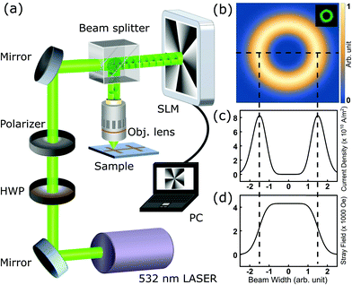
The schematic diagram of the experimental setup is shown in Fig. 1(a). A linearly polarized 532 nm laser was sent onto a reflective spatial light modulator (SLM) while the computer-generated hologram of the desired mode was applied to the liquid crystal display of the SLM. The phase of the incident plane waves was modulated, and the reflective beam was transformed into an LG beam. The twisted light was guided onto a 50x objective lens, focusing it onto the sample. The intensity of the twisted light can be represented as18 | (1) |
In eqn (1), the beam size  , p is the radial index,
 ![[small script l]](https://www.rsc.org/images/entities/i_char_e146.gif) is the topological charge, P0 is the power of the beam, λ is the wavelength, and
is the topological charge, P0 is the power of the beam, λ is the wavelength, and  is a generalized Laguerre polynomial. Fig. 1(b) shows the numerical intensity result for the LG beam (
![[small script l]](https://www.rsc.org/images/entities/i_char_e146.gif) = 5, p = 0), while the inset depicts the corresponding experimental intensity.
= 5, p = 0), while the inset depicts the corresponding experimental intensity.
The gradient of the electric field of twisted light drives the conducting electrons to form a circular current. The beam's electric field acting on the metal surface can further be represented by19
 | (2) |
The current loop driven by the helical phase gradient can then be described by19
 | (3) |
The effective mass  of the conducting electron in Pt is set to be
  = 13me = 1.18 × 10⁻²⁹ kg.20Fig. 1(c) is the line profile of the simulated circular current density of eqn (3). Consequently, the current loop drives the perpendicular magnetic field by Ampère's law:
 | (4) |
The numerical result presented in Fig. 1(d) shows that the field has a sufficient order (∼4 kOe) to potentially flip the magnetization of Co, in which the coercivity is around 0.2 kOe in the in-plane direction and 0.1 kOe in the perpendicular direction.1 The numerical calculation presented here provides a conceptual demonstration, and it implies that the OAM of light has the capability to switch a magnetic domain in an appropriate sample. The induced magnetic fields with other values of ![[small script l]](https://www.rsc.org/images/entities/i_char_e146.gif) and the corresponding magnetic flux are shown in Fig. S1 (ESI†).
and the corresponding magnetic flux are shown in Fig. S1 (ESI†).
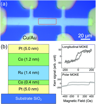
The IEC device's optical microscopy image is shown in Fig. 2(a), and the stacked Pt/Co/Ru/Co/Pt heterostructure is presented in Fig. 2(b). The top Pt layer protects the Co layer from oxidation, while the bottom Pt layer separates the Co layer from the SiO2 surface. The middle Ru layer allows the coupling of the two Co layers through an IEC effect. In order to have strong perpendicular magnetic anisotropy (PMA) and in-plane magnetic anisotropy (IMA) simultaneously in both Co layers, the Ru layer was designed to have a thickness of 1.4 nm, as can be seen in the previous study.1 The longitudinal and polar Kerr signals of this sample were measured by using Kerr microscopy and are presented in the right portion of Fig. 2(b).
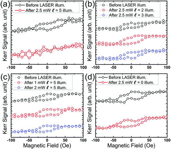
Twisted light was then introduced onto the above described IEC sample surface using an objective lens (50x). The focused spot size is around 5 μm in diameter. The laser was aimed at the middle region of the sample's long axis and scanned on a 15 μm by 40 μm region (red-dotted area shown in Fig. 2(a)) with a step size of 5 μm and a time duration of 30 sec. After the illumination process, the sample's hysteresis loops were recorded via a Kerr microscope. Fig. 3 displays the hysteresis loops under different laser conditions. Fig. 3(a) displays the case wherein the ferromagnetic-hysteresis loop successfully changed into a paramagnetic-hysteresis loop. In this case, the twisted light was set to hold ![[small script l]](https://www.rsc.org/images/entities/i_char_e146.gif) = 5 at P0 = 2.5 mW. This phenomenon, however, happened beyond a certain threshold condition. For instance, the ferromagnetic-hysteresis loop of the sample remained almost the same when the light carried lower topological charge values and when the power of the beam was insufficient as shown in Fig. 3(b) and (c), respectively. The tendencies are recorded in Fig. S2 (ESI†). These experiments revealed that there are thresholds for twisted light to write an IEC device. Furthermore, Fig. 3(d) displays the result of an unchanged hysteresis loop when the laser had sufficient beam power of 2.5 mW without OAM, implying that the laser power was not high enough to raise the temperature to demagnetize the sample. Thus, the thermal effect is not the primary origin of the observed ferromagnetic–paramagnetic switching. In addition, in order to examine the requirements of an IEC device, a Co thin film encapsulated by Pd layers on a SiO2/Si substrate, Pd(2 nm)/Co(3 nm)/Pd(5 nm), was illuminated by twisted light. The results show that the MA did not change as shown in Fig. S3 (ESI†), indicating that the pinning effect provided by the interlayer exchange coupling is necessary for the desired observation to occur.
= 5 at P0 = 2.5 mW. This phenomenon, however, happened beyond a certain threshold condition. For instance, the ferromagnetic-hysteresis loop of the sample remained almost the same when the light carried lower topological charge values and when the power of the beam was insufficient as shown in Fig. 3(b) and (c), respectively. The tendencies are recorded in Fig. S2 (ESI†). These experiments revealed that there are thresholds for twisted light to write an IEC device. Furthermore, Fig. 3(d) displays the result of an unchanged hysteresis loop when the laser had sufficient beam power of 2.5 mW without OAM, implying that the laser power was not high enough to raise the temperature to demagnetize the sample. Thus, the thermal effect is not the primary origin of the observed ferromagnetic–paramagnetic switching. In addition, in order to examine the requirements of an IEC device, a Co thin film encapsulated by Pd layers on a SiO2/Si substrate, Pd(2 nm)/Co(3 nm)/Pd(5 nm), was illuminated by twisted light. The results show that the MA did not change as shown in Fig. S3 (ESI†), indicating that the pinning effect provided by the interlayer exchange coupling is necessary for the desired observation to occur.
Fig. 4 shows the results of the polar magnetic analysis on the IEC sample before and after twisted light illumination. The angle for the polar magnetic analysis is defined by the sample's long axis with respect to the external in-plane magnetic field. At each angle, the coercivity can be obtained by recording which magnetic field led the Kerr signal to cross through the zero point, i.e., the needed magnetic field to flip the sample's magnetization. Fig. 4(a) is the comparison of the polar diagrams before and after twisted light illumination. The red line is a guide-to-the-eye that indicates the sample's magnetic anisotropy (MA) in the in-plane direction. The MA is distorted after illumination in contrast to its prior nearly uniform pattern. Fig. 4(b) shows that the coercivity in the hysteresis loop dramatically drops at 0° (yellow), 10° (green), 140° (blue) and 160° (orange) after illumination. The colors used in each of these hysteresis loops are the same as their corresponding data points in the polar diagrams in Fig. 4(a). The hysteresis loops for other angles are provided in Fig. S4 and S5 of the ESI.† This phenomenon of MA change happens for both positive and negative topological charge of twisted light in the other sample as shown in Fig. S6 (ESI†).
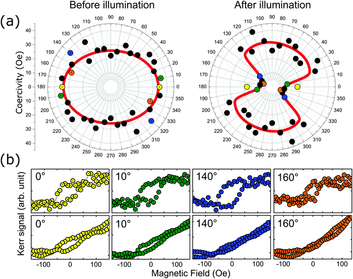 | ||
Fig. 4 The comparison between the polar coercivity analysis before and after OAM laser illumination. The laser's condition is: ![[small script l]](https://www.rsc.org/images/entities/i_char_e146.gif) = 5, 2.5 mW. (a) The left-hand-side chart is the initial MA orientation, and the right-hand-side is the final MA orientation after twisted light illumination. (b) Four examples are selected to represent the coercivity with dramatic reductions. The upper four Kerr loops are the initial states at 0° (yellow), 10° (green), 140° (blue), and 160° (orange) sample orientations, respectively. The lower four Kerr loops are the corresponding final states. The complete data sets are also shown in Fig. S2 and S3 (ESI†). = 5, 2.5 mW. (a) The left-hand-side chart is the initial MA orientation, and the right-hand-side is the final MA orientation after twisted light illumination. (b) Four examples are selected to represent the coercivity with dramatic reductions. The upper four Kerr loops are the initial states at 0° (yellow), 10° (green), 140° (blue), and 160° (orange) sample orientations, respectively. The lower four Kerr loops are the corresponding final states. The complete data sets are also shown in Fig. S2 and S3 (ESI†). | ||
Discussion
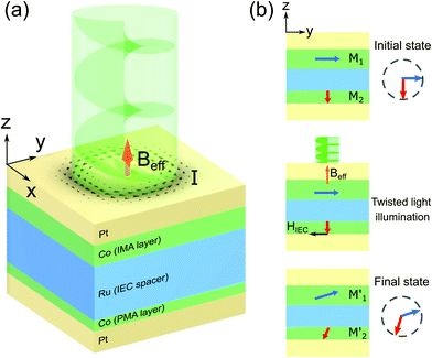
From the above observation, the variations in the MA caused by twisted light in the IEC device are clear. On the other hand, the changed hysteresis loop is reversible as Fig. S7 (ESI†) shows. We suggest that only the magnetizations of Co are involved during the MA changing process. Here we provided a possible mechanism to explain such changes in MA as shown in Fig. 5. The initial state of the spin configuration in the Co/Ru/Co system is supposed to be orthogonally aligned: the top 1.2 nm Co layer magnetization M1 is IMA and the bottom 0.4 nm Co layer M2 is PMA. The easy axis of the IMA is supposed to be parallel with the geometric long axis (y-axis in Fig. 5) of the device. Further, the middle Ru layer plays the role of coupling the whole spin configuration.1 From the numerical simulation of the twisted light interacting with Pt in Fig. 1(b)–(d), we already know that the twisted light drives the loop current, which then induces a perpendicular magnetic field (see Beff in Fig. 5(a)) while illuminating. The calculated strength of this magnetic field (∼4 kOe) is one-order larger than what we observed for the coercivities of the sample (∼50 Oe in the in-plane and ∼350 Oe in the perpendicular direction, as shown in Fig. 2(b)). Accordingly, the magnetizations of Co flipped by the induced effective magnetic field from twisted light are highly possible. So, after the twisted light illumination (Fig. 5(b)), we speculate that the top in-plane magnetization M1 is tilted into M1′ by the effective magnetic field Beff, and then the interlayer exchange coupling provides another effective field Heff to tilt M2 into M2′. The final state M1′ and M2′ is supposed to be a metastable state. Considering the two spin configurations in Fig. 5(b), the responses in the MA measurement between the initial and final states are supposed to be different as Fig. 4 shows.In conclusion, the variations of the MA of an IEC system driven by twisted light are successfully demonstrated in this study. Compared to the current AOS method done using SAM with a pulsed laser,8 the vortex nature of the twisted light combined with the IEC system makes it possible to employ a lower power consuming AOS process. Although the detailed mechanism remains unknown, the phenomena presented here are clear and repeatable. We expect that this discovery could further expand the potential applications of the OAM of light.
Methods
We used a 532 nm continuous laser to pass through the setup shown in Fig. 1. The laser intensity was adjusted using an attenuator, while the light's orbital angular momentum (OAM) was modified via the spatial light modulator (SLM) using appropriate parameters. The diameter of our laser dot on the sample is about 5 μm. We irradiated the sample using the OAM laser for 30 seconds and then immediately transported it to the Kerr microscopy setup for magnetic property measurements.21 The twisted light laser's skin depth is estimated to be about 6.87 nm, which is deep enough to penetrate the protective Pt layer (5 nm) and attend to the Co layer. The sample is prepared via the magnetron sputtering technique.Stacks with a structure of Pt(5)/Co(0.4)/Ru(1.4)/Co(1.2)/Pt(5 nm) (Fig. 2(b)) were deposited on Si/SiO2 substrates by the magnetron sputtering technique (TMR R&D sputtering system, ULVAC) with a base pressure of 1.0 × 10⁻⁶ Pa at room temperature. During the deposition process, an in-plane magnetic field to induce the easy axis was provided. The thicknesses in brackets are the nominal thicknesses based on the pre-calibrated deposition rates and deposition time. TEM characterization of the samples can be found in ref. 1. The stacks were then patterned via ultraviolet lithography and argon ion etching into Hall bars with widths of 10 μm as illustrated in Fig. 2(a). Cu/Au electrodes were finally deposited to connect the terminals of the Hall bars. Before the optical measurements, the magnetic properties were measured using a vibrating sample magnetometer (VSM, Micro Sense) while magnetotransport properties such as the Hall resistance Rxy were measured by the 4-terminal method to check the magnetic anisotropy. The transport properties can also be found in ref. 1.
Data availability
All relevant data are available from the authors. Requests for data and materials should be addressed to Y.-W. Lan.Author contributions
In this report, C.-I. L., S.-A. W., and K. B. S. performed the experiments, data analysis, and the manuscript preparation. The IEC heterojunction samples were prepared by X. W. and G. Y. The technique of the twisted light beam was provided by T.-H. L. The data explanation, Kerr microscopy measurements and the sample without IEC were deeply supported by C.-M. L. and W.-C. L. This project was conceived and led by Y.-W. L.Conflicts of interest
The authors declare no competing interests.Acknowledgements
This study is financially supported by the Ministry of Science and Technology of Taiwan through grants (MOST 108-2112-M-003-010-MY3) and (MOST 108-2112-M-003-009).References
- X. Wang, et al., Field-Free Programmable Spin Logics via Chirality-Reversible Spin–Orbit Torque Switching, Adv. Mater., 2018, 30, 1801318, DOI:10.1002/adma.201801318.
- Y. Sheng, K. W. Edmonds, X. Ma, H. Zheng and K. Wang, Adjustable Current-Induced Magnetization Switching Utilizing Interlayer Exchange Coupling, Adv. Electron. Mater., 2018, 4, 1800224, DOI:10.1002/aelm.201800224.
- M. L. M. Lalieu, R. Lavrijsen and B. Koopmans, Integrating all-optical switching with spintronics, Nat. Commun., 2019, 10, 110, DOI:10.1038/s41467-018-08062-4.
- C. D. Stanciu, et al., All-Optical Magnetic Recording with Circularly Polarized Light, Phys. Rev. Lett., 2007, 99, 047601, DOI:10.1103/PhysRevLett.99.047601.
- A. Manchon, et al., Current-induced spin-orbit torques in ferromagnetic and antiferromagnetic systems, Rev. Mod. Phys., 2019, 91, 035004, DOI:10.1103/RevModPhys.91.035004.
- G. Molina-Terriza, J. P. Torres and L. Torner, Twisted photons, Nat. Phys., 2007, 3, 305–310, DOI:10.1038/nphys607.
- M. Padgett, Light's twist, Proc. R. Soc. A, 2014, 470, 20140633, DOI:10.1098/rspa.2014.0633.
- S. Mangin, et al., Engineered materials for all-optical helicity-dependent magnetic switching, Nat. Mater., 2014, 13, 286–292, DOI:10.1038/nmat3864.
- A. Hassdenteufel, et al., Thermally assisted all-optical helicity dependent magnetic switching in amorphous Fe(100−x)Tb(x) alloy films, Adv. Mater., 2013, 25, 3122–3128, DOI:10.1002/adma.201300176.
- Y. Shi, et al., Magnetic Field Generation in Plasma Waves Driven by Copropagating Intense Twisted Lasers, Phys. Rev. Lett., 2018, 121, 145002, DOI:10.1103/PhysRevLett.121.145002.
- J. Watzel and J. Berakdar, Centrifugal photovoltaic and photogalvanic effects driven by structured light, Sci. Rep., 2016, 6, 21475, DOI:10.1038/srep21475.
- W. Yang, H. Yang, Y. Cao and P. Yan, Photonic orbital angular momentum transfer and magnetic skyrmion rotation, Opt. Express, 2018, 26, 8778–8790, DOI:10.1364/OE.26.008778.
- G. F. Quinteiro and P. I. Tamborenea, Theory of the optical absorption of light carrying orbital angular momentum by semiconductors, EPL, 2009, 85, 47001, DOI:10.1209/0295-5075/85/47001.
- G. F. Quinteiro and J. Berakdar, Electric currents induced by twisted light in Quantum Rings, Opt. Express, 2009, 17, 20465–20475, DOI:10.1364/OE.17.020465.
- G. F. Quinteiro, P. I. Tamborenea and J. Berakdar, Orbital and spin dynamics of intraband electrons in quantum rings driven by twisted light, Opt. Express, 2011, 19, 26733–26741, DOI:10.1364/OE.19.026733.
- Z. Ji, et al., Photocurrent detection of the orbital angular momentum of light, Science, 2020, 368, 763, DOI:10.1126/science.aba9192.
- J. Watzel and J. Berakdar, All-optical generation and ultrafast tuning of non-linear spin Hall current, Sci. Rep., 2018, 8, 17102, DOI:10.1038/s41598-018-35378-4.
- J. Arlt, T. Hitomi and K. Dholakia, Atom guiding along Laguerre–Gaussian and Bessel light beams, Appl. Phys. B: Lasers Opt., 2000, 71, 549–554, DOI:10.1007/s003400000376.
- K. Y. Bliokh, et al., Theory and applications of free-electron vortex states, Phys. Rep., 2017, 690, 1–70, DOI:10.1016/j.physrep.2017.05.006.
- S. Kasap, Principles of Electronic Materials and Devices, McGraw-Hill, Inc., 2005 Search PubMed.
- C.-C. Hsu, et al., Magnetic decoupling of Fe coverage across atomic step of MoS2 flakes on SiO2 surface, J. Phys. D: Appl. Phys., 2017, 50, 415001, DOI:10.1088/1361-6463/aa86d2.
Footnote |
| † Electronic supplementary information (ESI) available. See DOI: 10.1039/d1nh00063b |
| This journal is © The Royal Society of Chemistry 2021 |

