 Open Access Article
Creative Commons Attribution 3.0 Unported Licence
Tuning adlayer-substrate interactions of graphene/h-BN heterostructures on Cu(111)–Ni and Ni(111)–Cu surface alloys†
Jianmei Huanga,
Qiang Wang *a,
Pengfei Liua,
Guang-hui Chen
 b and
Yanhui Yang
 *a
*a
aSchool of Chemistry and Molecular Engineering, Institute of Advanced Synthesis (IAS), Nanjing Tech University, Nanjing 211880, P. R. China. E-mail: wangqiang@njtech.edu.cn; yhyang@njtech.edu.cn
bDepartment of Chemistry, Shantou University, Shantou, Guangdong 515063, P. R. China
First published on 6th January 2021
Abstract
The evolution of the interface and interaction of h-BN and graphene/h-BN (Gr/h-BN) on Cu(111)–Ni and Ni(111)–Cu surface alloys versus the Ni/Cu atomic percentage on the alloy surface were comparatively studied by the DFT-D2 method, including the critical long-range van der Waals forces. Our results showed that the interaction strength and interface distance of Gr/h-BN/metal can be distinctly tuned by regulating the chemical composition of the surface alloy at the interface. The initially weak interaction of h-BN/Cu(111)–Ni increased linearly with increasing Ni atomic percentage, and the interface distances decreased from ∼3.10 to ∼2.10 Å. For the h-BN/Ni(111)–Cu interface, the strong interaction of the NtopBfcc/hcp stacking decreased sharply with increasing Cu atomic percentage from 0% to 50%, and the interface distances increased from ∼2.15 to ∼3.00 Å; meanwhile, the weak interaction of the BtopNfcc/hcp stacking decreased slightly with increasing Cu atomic percentage. The absorption of graphene on h-BN/Cu(111)–Ni with BtopNhollow/NtopBfcc and BtopNhollow/BtopNfcc stacking was more energetically favorable than that with NtopBhollow/NtopBfcc and NtopBhollow/BtopNfcc at Ni atomic percentages under 75%, while the interaction energy of graphene on h-BN/Cu(111)–Ni increased sharply at Ni atomic percentages higher than 75% for the BtopNhollow/NtopBfcc and NtopBhollow/NtopBfcc stacking. In contrast, the interaction between graphene and the h-BN/Ni(111)–Cu surface increased sharply at Cu atomic percentages lower than 25% and decreased sharply at Cu atomic percentages higher than 75%. The interaction energies were higher when the percentage of Cu atom was between 25% and 75%. The analysis of charge transfer and density of states provided further details on the changing character and evolution trends of the interactions among graphene, h-BN, and Cu–Ni surface alloy versus the Ni/Cu atomic percentage.
1. Introduction
Graphene/hexagonal boron nitride (Gr/h-BN) heterostructures have attracted much interest due to their intriguing electronic and mechanical properties.1,2 Great effort has been devoted to growing Gr/h-BN heterostructures with various vertically stacked or in-plane pieced patterns by chemical vapor deposition (CVD) method on various metal substrates.2–6 In general, Gr/h-BN heterostructures can be grown on weakly binding metal surfaces such as Cu,1,2,7–9 Ir,5 Rh,4 and Pt(111),10 resulting in a hetero-expitaxial growth mechanism of h-BN growth along the graphene edge1,8 or graphene nucleation at the corners of the triangular h-BN grains.3 In this case, the common feature of these quasi-free-standing Gr/h-BN heterostructures completely remains their intrinsic electronic properties due to the weak interfacial binding by Pauli exclusion and van der Waals (vdW) attraction.5,10 In contrast, Gr/h-BN heterostructures grown on strongly interacting metal substrates, such as Ni,11,12 Ru,13–15 and Re(111),6 result in the coexistence of perfectly patched Gr/h-BN heterostructures linked with predominant zigzag-type boundaries6,12 because the graphene and h-BN favor growth into separated domains. In addition, the intrinsic electronic properties of the Gr/h-BN heterostructures are almost completely inhibited due to the strong interfacial chemical bonds and charge transfer.6 In this regard, the complex growth mechanisms and electronic properties of the Gr/h-BN heterostructures strongly depend on the interfacial interaction among graphene, h-BN and the metal substrate. Therefore, it is highly desirable to tune the interfacial interaction strength of graphene, h-BN and the metal substrate to facilitate controllable growth and electronic properties of the Gr/h-BN heterostructure.One possibility for tuning the interfacial interaction strength of a Gr/h-BN heterostructure is changing the chemical composition of the metal surface alloy at the interface. Recently, a single-layer Gr/h-BN in-plane heterostructure was successfully synthesized on Cu–Ni alloy substrate by a two-step low pressure CVD method.3 The Cu–Ni alloy substrate showed excellent catalytic performance, which not only enhanced the decomposition capability of polyaminoborane residues and the crystal quality of h-BN, but also eliminated random nucleation and promoted the growth of graphene through isothermal segregation. On the Cu–Ni alloy surface, graphene nucleated only at the top corners of the triangular h-BN grains and grew along the edge orientation of the as-formed h-BN with a fast growth rate. Subsequently, h-BN/graphene vertical stacked heterostructures were also successfully synthesized on the Cu–Ni alloy substrate by a CVD method in the same group.16 The interface and interactions of Gr/h-BN on pure Cu(111) and Ni(111) substrates have been studied in recent experimental and theoretical studies,7,11,12 which revealed the difference in the growth mechanisms and interfacial properties of the Gr/h-BN heterostructure on the weakly coupling Cu(111) and strongly interacting Ni(111) surfaces. However, few relevant experimental and theoretical investigations have been reported on the metal surface alloy, which is undoubtedly crucial to better understand the growth and electronic properties of Gr/h-BN heterostructures.
In our recent study, the interface interaction and properties of the Gr/h-BN heterostructures on pure Cu(111) and Ni(111) surfaces were investigated.17 The results showed that h-BN and Gr/h-BN have two typical types of interactions, weakly coupled and strong, with pure metal substrates of Cu(111) and Ni(111). The NtopBhcp/fcc stacking configurations of h-BN and Gr/h-BN on Ni(111) were strong chemisorption, while the BtopNhcp/fcc stacking configurations on Ni(111) and both NtopBhcp/fcc and BtopNhcp/fcc configurations on Cu(111) were weak physisorption. In this study, we would like to further attempt to tune the two typical interfacial interactions and surface electronic structures by regulating the chemical compositions of the surface alloys at the interface. Therefore, two types of Cu(111)–Ni and Ni(111)–Cu surface alloys with five representative Cu/Ni ratios were chosen as representatives of surface alloys to study the evolution of the interfacial interaction and properties with various Gr/h-BN heterostructures.3,16 The goal of this work was to elucidate the nature of the interfacial interactions and electronic properties of Gr/h-BN heterostructures on Cu–Ni surface alloys and further elaborate the influence trends of the surface alloys on the interfacial interactions and transport properties by fine-tuning the atomic percentages of Ni and Cu on the surface of Cu(111) and Ni(111).
2. Computational methods and models
All spin-polarized density functional theory (DFT) calculations were performed using the Vienna Ab initio Simulation Package (VASP).18 The projector augmented wave (PAW) pseudopotential19,20 was used for the electron–ion interactions and Perdew–Burke–Ernzerhof (PBE) generalized gradient approximation (GGA) was used for the exchange–correlation functional.21–23 Long-range dispersion corrections were considered within the DFT-D2 method. The dispersion coefficients C6 and vdW radii R0 for B, C, N, Ni, and Cu used in our DFT-D2 method were taken from previous work.24,25 The scale factor S6 was 0.75.26,27 The energy cutoff was set to 400 eV in the plane-wave basis set, and all calculations used a convergence criterion of 10−6 eV.The pure metal surfaces were modeled by six-layer Cu(111) and Ni(111) periodic slab with the lowest two layers fixed at their equilibrium bulk phase positions, while the upper four layers were allowed to relax. The surface alloys of Cu(111)–Ni and Ni(111)–Cu were built by substituting the Cu/Ni atoms on the topmost layer of optimized p(2 × 2) Cu(111) and Ni(111) with the Ni/Cu atoms. In the surface layers of Cu(111)–Ni and Ni(111)–Cu, the number ratios of Ni to Cu or Cu to Ni atoms are 0/1, 1/3, 1/1, 3/1, and 1/0, corresponding to Ni/Cu concentrations of 0%, 25%, 50%, 75%, and 100%, respectively.
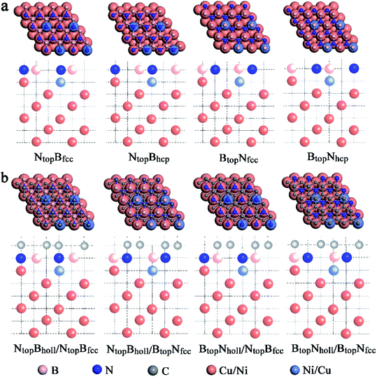
When adsorbing the h-BN layer on the Cu(111)–Ni or Ni(111)–Cu surface alloy, there were four different configurations with B and N atoms each located at top and hollow (fcc or hcp) sites, denoted as NtopBfcc, NtopBhcp, BtopNfcc, and BtopNhcp, respectively, as shown in Fig. 1a. Furthermore, when adsorbing the graphene layer on h-BN/Cu(111)–Ni or h-BN/Ni(111)–Cu substrates, there were also four different configurations, denoted as BtopNhollow/NtopBfcc, NtopBhollow/NtopBfcc, BtopNhollow/BtopNfcc and NtopBhollow/BtopNfcc, respectively, as shown in Fig. 1b. Each vacuum region was at least 15 Å in the direction perpendicular to the interface to avoid interactions with its own image. The Brillouin-zone integrations were performed with a 21 × 21 × 1 k-point mesh. It was assumed that the Gr/h-BN layers were grown on the Cu(111)–Ni and Ni(111)–Cu surface alloys. Thus, the lattice constants of Cu(111) (2.52 Å) and Ni(111) (2.45 Å) were employed in the Gr/h-BN/Cu(111)–Ni and Gr/h-BN/Ni(111)–Cu systems with lattice mismatches of 2.2% and 0.7% for the h-BN layer and 2.0% and 0.8% for the graphene layers, respectively. During the geometry optimization of Gr/h-BN/Cu(111)–Ni and Gr/h-BN/Ni(111)–Cu, the bottom two layers of the metal were fixed at their bulk lattice positions, while other layers of graphene, h-BN and metal were fully relaxed. The global transferred charges were calculated by atomic Bader charge analysis.28,29
3. Results and discussion
3.1. h-BN on Cu(111)–Ni and Ni(111)–Cu surfaces
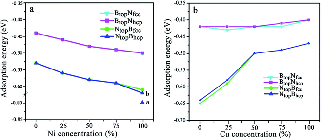 | ||
| Fig. 2 Evolution of the adsorption energy of monolayer BN on Cu(111)–Ni and Ni(111)–Cu surface alloys versus Ni and Cu concentration on the Cu(111)–Ni and Ni(111)–Cu alloy surface. | ||
The results in Fig. 2 and Table S1† show that the interaction energies and interlayer distances of h-BN on the Cu(111)–Ni and Ni(111)–Cu surface alloys mainly depended on the Ni/Cu atomic percentages of the surface alloys and the stacking configuration. Fig. 2a shows that the interaction energy of monolayer h-BN increased linearly with increasing Ni atomic percentage on the Cu(111)–Ni alloy surface. The interaction energies of h-BN on the Cu(111)–Ni surface increased linearly from −0.53 to −0.61 eV per BN for the NtopBfcc and NtopBhcp stacking (−0.80 eV per BN for the aNtopBfcc andaNtopBhcp) and from −0.44 to −0.50 eV per BN for the BtopNfcc and BtopNhcp stacking as the Ni atomic percentages increased from 0% to 100% in the surface alloys. Accordingly, the interlayer vertical distances, dBN-M, from the h-BN layer to the topmost layer of Cu(111)–Ni decreased gradually from 2.93 to 2.71 (2.09) Å for the NtopBfcc and NtopBhcp stacking and from 3.10 to 2.95 Å for the BtopNfcc and BtopNhcp stacking. Obviously, the interaction energies of monolayer h-BN on Cu(111)–Ni with the NtopBfcc and NtopBhcp stacking were higher than those with the BtopNfcc and BtopNhcp stacking by about 0.10 eV per BN.
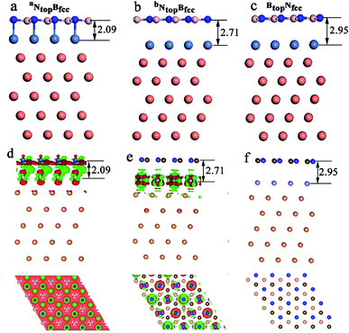
Interestingly, when adsorbing monolayer h-BN on the Cu(111)–Ni(100%), there are three types of stable adsorption configurations of the aNtopBfcc/aNtopBhcp, bNtopBfcc/bNtopBhcp, and BtopNfcc/BtopNhcp stacking, as illustrated in Fig. 2a and 3. The interaction energy profiles of h-BN adsorption in the NtopBfcc and NtopBhcp stacking geometries calculated at different interlayer distances from the h-BN layer to the topmost layer of Cu(111)–Ni clearly exhibited two stable local minima at the separations of 2.09 Å (denoted as aNtopBfcc/aNtopBhcp) and 2.71/2.70 Å (denoted as bNtopBhcp/bBtopNfcc), as illustrated in Fig. S2.† The differences in the interaction energies and interlayer distances between the NtopBfcc and NtopBhcp configurations were negligible for monolayer h-BN on the Cu(111)–Ni and Ni(111)–Cu alloy surfaces. For the sake of brevity, only the NtopBfcc configuration is depicted and discussed in this study. For the aNtopBfcc stacking, as illustrated in Fig. 3a, the interaction energy of h-BN on Cu(111)–Ni(100%) is −0.80 eV per BN, which is significantly higher than that on pure Ni(111) by ∼0.15 eV per BN. The corresponding interlayer distance is 2.09 Å, which is shorter than that on pure Ni(111) by only 0.05 Å. However, for the bNtopBfcc stacking, as illustrated in Fig. 3b, the interaction energy of h-BN on Cu(111)–Ni(100%) is about −0.61/0.62 eV per BN, which is slightly lower than that on pure Ni(111) by about 0.03 eV per BN. Meanwhile, the corresponding interlayer distance is 2.71 Å, which is longer than that on pure Ni(111) by 0.57/0.58 Å. However, the interaction energy profiles of h-BN adsorption in the BtopNfcc stacking geometries exhibit only one minimum at a separation of 2.95 Å for the weak physisorption, as illustrated in Fig. 3c. The corresponding adsorption energy is −0.50 eV per BN, which is higher than that on pure Ni(111) by only 0.08 eV per BN, and the corresponding interlayer distance is 2.95 Å, which is shorter than that on pure Ni(111) by only 0.06 Å.
On the Ni(111)–Cu surface, Fig. 2b shows that the interaction energies of h-BN on the Ni(111)–Cu surface decrease sharply from −0.65 to −0.50 eV per BN as the Cu atomic percentage increases from 0% to 50% for the NtopBfcc and NtopBhcp stacking with strong interaction. Accordingly, the interlayer vertical distances, dBN-M, from the h-BN layer to the topmost layer of Ni(111)–Cu increase gradually from 2.14 to 2.90 Å. Subsequently, the interaction energies decrease slightly from −0.50 to −0.47 eV per BN at Cu surface concentrations higher than 50%, and the interlayer distances from the h-BN layer to the Ni(111)–Cu surface only increase by about 0.06 Å. For the BtopNfcc and BtopNhcp stacking with weak interaction, the interaction energies of monolayer h-BN on the Ni(111)–Cu surface decrease slightly from −0.43 to −0.40 eV per BN as the Cu atom concentration increases from 0% to 100% on the alloy surface, and the interlayer vertical distances from the h-BN layer to the Ni(111)–Cu surface are only increased by about 0.06 Å. Similarly, the interaction energies of the NtopBfcc and NtopBhcp stacking are higher than that of the BtopNfcc and BtopNhcp stacking when the monolayer h-BN adsorbs on the Ni(111)–Cu alloy surfaces. Additionally, the difference in the adsorption energies and interlayer distances between the FCC and HCP configurations is negligible for monolayer h-BN on the Cu(111)–Ni and Ni(111)–Cu alloy surfaces.
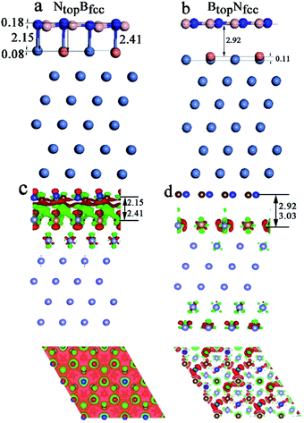
In addition, significant distortion occurs for the interfacial layers when adsorbing the monolayer h-BN on Ni(111)–Cu with 25% Cu, as shown in Table S1† and Fig. 4. For the NtopBfcc and NtopBhcp stacking, both the h-BN layer and topmost layer of Ni(111)–Cu afford significant distortion, as shown in Fig. 4a (only NtopBfcc stacking is shown). One N atom in h-BN bonds with the Cu atom by a longer N–Cu chemical bond of 2.41 Å, while other three N atoms of h-BN bond with the Ni atoms by shorter N–Ni chemical bonds of 2.l5 Å, as illustrated in Fig. 4a, resulting in the displacement of Cu atom downward by 0.08 Å relative to the Ni atoms in the same surface layer. Moreover, it causes the N atom bonded with Cu to move up by 0.18 Å relative to the N atoms bonded with Ni atoms. If the N atoms bonded with Ni atoms are taken as the reference, one B atom located at the Ni–Ni–Ni hollow site moves down by 0.14 Å, while three other B atoms located at the Ni–Ni–Cu hollow site are at the same height. More interestingly, for the BtopNfcc and BtopNhcp stacking, distortion occurs only at the topmost layer of Ni(111)–Cu alloys, as shown in Fig. 4b (only show BtopNfcc stacking). The Cu atoms on the Ni(111)–Cu alloy surface move up by about 0.11 Å relative to the Ni atoms in the same surface layer, while the h-BN layer is almost intact due to the relatively weak interfacial interaction, with larger interlayer distances of about 3.00 Å.
When the Cu atomic percentage is 50%, 75% or 100%, Table S1† shows that the interfacial layers become less distorted for NtopBfcc and NtopBhcp stacking because the interfacial interaction decreases with increasing interlayer vertical distance. In addition, the interaction energy and interlayer distance are not significantly different for h-BN on both the Ni(111)–Cu(100%) and pure Cu(111) surfaces. For the NtopBfcc and NtopBhcp stacking, the interaction energies of h-BN on Ni(111)–Cu(100%) are −0.47 eV per BN, which is lower than that on pure Cu(111) by 0.06 eV per BN, and the corresponding interlayer distances are ∼2.96 Å, which is longer than that on pure Cu(111) by only 0.03 Å. Differently, for the BtopNfcc and BtopNhcp stacking, the interaction energy of h-BN on Ni(111)–Cu(100%) is −0.40 eV per BN, which is lower than that on pure Cu(111) by about 0.04 eV per BN; however, the corresponding interlayer distance is ∼3.07 Å, which is shorter than that on pure Cu(111) by only 0.04–0.01 Å, respectively.
Similarly, for the NtopBfcc stacking with strong interfacial interaction between h-BN and Ni(111)–Cu(25%), the side and top views in Fig. 4c show that remarkable charge transfer also occurs in the interface between h-BN and Ni(111)–Cu(25%), resulting in strong chemical bonds between the N atoms of h-BN and the Ni or Cu atoms on the Ni(111)–Cu(25%) surface. The charge mainly transfers from the Ni and Cu atoms to the B atoms through the N atoms of the h-BN layer; as a result, the charge density increases significantly at the B atoms while it decreases at the N atoms of the h-BN layer, as shown in the top view of Fig. 4c. The Bader charge analysis further confirms that the B atoms have +2.10 e per atom, which is more than that in the isolated h-BN by 0.03 e per atom, and the N atoms have −2.14 e per atom, which is more than that in the isolated h-BN by only 0.01 e per atom. The surface Ni and Cu atoms and subsurface Ni atoms in Ni(111)–Cu(25%) deplete +0.02, +0.07, and +0.01 e per atom, respectively. For the BtopNfcc stacking with weak interfacial interaction between h-BN and Ni(111)–Cu(25%), there is almost no charge transfer, and only minor charge redistribution and electronic polarization at the interface between the h-BN layer and surface layer of Cu(111)–Ni(25%) occur, as illustrated in Fig. 4d.
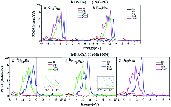
Compared with the pristine DOS of free h-BN in Fig. S1,† for the h-BN on Cu(111)–Ni(25%) with weak interfacial interaction, the PDOSs of the NtopBfcc and NtopBfcc stacking are similar, and non-zero charge density occurs at the Fermi level, as illustrated in Fig. 5a and b; this implies weak interfacial interactions of the π-orbitals of h-BN and the 3d orbitals of the Cu(111)–Ni(25%) surface. It can be seen that the d-states of the surface Cu atoms on Cu(111)–Ni(25%) are only slightly changed due to the embedded Ni atoms compared to those on Cu(111). However, the d-states of the Ni atoms are pronounced near the Fermi level, leading to strong overlaps with the d-states of the surface Cu atoms at −0.8 eV. This could explain the formation of the homogeneous NiCu surface alloy with strong NiCu bonding interactions.
For h-BN on Cu(111)–Ni(100%) with strong interfacial interaction, the PDOSs of the aNtopBfcc stacking in Fig. 5c show higher charge densities of states around the Fermi level in comparison to the pristine PDOS of free h-BN in Fig. S1.† Frontier orbital theory indicates that a system with higher frontier electron density is chemically reactive. In this regard, the h-BN on Cu(111)–Ni(100%) with the aNtopBfcc stacking would be more chemically active than the free h-BN due to the interfacial interaction and charge transfer. In addition, several new peaks appear around 4.8, 2.0, 0.2, −0.5, and −2.0 eV for the aNtopBfcc stacking on the curves of the N-p and Ni-d surface states, as illustrated in Fig. 5c. These new peaks indicate strong N–Ni chemical bonding across the interface, which is caused by the hybridization between the N-p orbitals of h-BN and the 3d orbitals of Ni in the Cu(111)–Ni(100%) surface. In contrast, for the bNtopBfcc and BtopNfcc stacking with medium and weak interfacial interactions, the charge densities near the Fermi level are remarkably lower than those of the aNtopBfcc stacking, as shown in Fig. 5d and e; meanwhile, a few changes can still be observed on the PDOS of B, N and Ni in comparison to the pristine PDOS of free h-BN due to their interfacial interaction, indicating the weaker interfacial interaction and lower surface reactivity of the bNtopBfcc and BtopNfcc stacking than of the aNtopBfcc stacking.
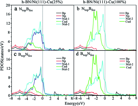
The PDOSs of the h-BN on the Ni(111)–Cu(25%) and Ni(111)–Cu(100%) surfaces are shown in Fig. 6. In comparison to the pristine PDOS of free h-BN in Fig. S1,† the PDOSs of the NtopBfcc stacking of h-BN/Ni(111)–Cu(25%) with strong interfacial interactions show higher charge densities of states near the Fermi level, and several new peaks appear at around 5.5, 4.8, 2.2, −0.8, and −2.8 eV in the curves of N-p, Cu-d and Ni-d, as illustrated in Fig. 6a. These new peaks indicate strong N–Ni and N–Cu chemical bonds across the interface, which are caused by hybridization between the N-p orbitals of h-BN and the 3d orbitals of Ni and Cu in the Ni(111)–Cu(25%) surface. For the BtopNfcc stacking of the h-BN/Ni(111)–Cu(25%) with weak interfacial interactions, the PDOSs show a lower charge density of states near the Fermi level, and there is no new peak and orbital hybridization, as illustrated in Fig. 6c. Similarly, for both the NtopBfcc and BtopNfcc stacking of h-BN on the Ni(111)–Cu(100%) surface, there is almost zero electron density near the Fermi level and no new peak/orbital hybridization compared with the pristine PDOS of free h-BN, as shown in Fig. 6b and d, implying lower chemical reactivity and weak interactions between the π-orbitals of h-BN and the 3d orbitals of the Ni(111)–Cu(100%) surface. Overall, these results suggest that the NtopBfcc stacking of h-BN on Cu(111)–Ni(100%) and Ni(111)–Cu(25%) with charge transfer and strong interfacial interaction would be more chemically reactive than the BtopNfcc stacking of the h-BN on Cu(111)–Ni(100%) and both NtopBfcc and BtopNfcc stacking of h-BN on Ni(111)–Cu(100%). These results also imply that the chemical reactivity depends not only on the composition of the alloy surface but also on the interfacial stacking of h-BN.
3.2. Graphene on the h-BN/Cu(111)–Ni and h-BN/Ni(111)–Cu surfaces
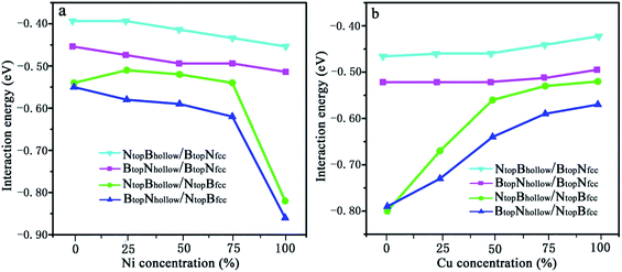 | ||
| Fig. 7 Evolution of the interfacial interactions of 1L-Gr/h-BN with Cu(111)–Ni and Ni(111)–Cu surface alloys versus Ni and Cu concentration on the Cu(111)–Ni and Ni(111)–Cu alloy surfaces. | ||
The results in Fig. 7 and Table S2† show that the interaction energies of Gr/h-BN/Cu–Ni depend on the Cu/Ni atomic percentage of the surface alloys and interfacial stacking configuration among graphene, h-BN and the Cu–Ni alloy surface. Similar to monolayer h-BN on Cu–Ni alloy surfaces, the interaction energies between the 1L-Gr/h-BN layer and Cu–Ni alloy surface with NtopBfcc/hcp stacking are always stronger than those with BtopNfcc/hcp stacking in 1L-Gr/h-BN/Cu–Ni. Likewise, the interaction energies between the graphene layer and h-BN/Cu–Ni substrate with BtopNhollow stacking are always stronger than that with the NtopBhollow stacking in 1L-Gr/h-BN/Cu–Ni.
The interaction energies between the 1L-Gr/h-BN and Cu–Ni alloy surfaces follow the order BtopNhollow/NtopBfcc > NtopBhollow/NtopBfcc > BtopNhollow/BtopNfcc > NtopBhollow/BtopNfcc, as illustrated in Fig. 7. Fig. 7a shows that the interaction energies between the 1L-Gr/h-BN layer and Cu(111)–Ni surfaces increase significantly with increasing Ni atomic percentage on the Cu(111)–Ni alloy surface for both BtopNhollow/NtopBfcc and NtopBhollow/NtopBfcc stacking, while it increases slightly for both BtopNhollow/BtopNfcc and NtopBhollow/BtopNfcc stacking. On the weakly coupled Cu(111) surface, the interaction energies of 1L-Gr/h-BN with the pure Cu(111) surface are −0.55 and −0.54 eV per supercell for BtopNhollow/NtopBfcc and NtopBhollow/NtopBfcc stacking, respectively, which are almost equal to the interfacial interaction of monolayer h-BN on the Cu(111) surface. The corresponding interlayer distance of dBN-M is 2.90 Å, which is shorter than that of monolayer h-BN on the Cu(111) surface by about 0.03 Å.
As the Ni atomic percentage increases from 0% to 75% on the Cu(111)–Ni surface layer, for the BtopNhollow/NtopBfcc stacking, the interaction energies of 1L-Gr/h-BN with the Cu(111)–Ni surface increase linearly from −0.55 to −0.62 eV per supercell, as illustrated in Fig. 7a, which are comparable with those of monolayer h-BN on the corresponding Cu(111)–Ni surfaces. The corresponding interlayer distances of dBN-M decrease linearly from 2.90 to 2.70 Å as the Ni atomic percentage increases from 0% to 75%. When the Ni atomic percentage is higher than 75%, the interaction energies of the 1L-Gr/h-BN with Cu(111)–Ni surface increase sharply from −0.62 to −0.86 eV per supercell, and the interlayer distances from h-BN layer to the Cu(111)–Ni surface decrease sharply from 2.70 to 2.07 Å.
Interestingly, for NtopBhollow/NtopBfcc stacking, the interaction energies between 1L-Gr/h-BN and the Cu(111)–Ni surface decrease slightly from −0.54 to −0.51 eV per supercell, followed by an increase from −0.51 to −0.54 eV per supercell, as the Ni atomic percentage increases from 0% to 75% on the Cu(111)–Ni surface layer, as illustrated in Fig. 7a; these energies are lower than those of monolayer h-BN on the corresponding Cu(111)–Ni surfaces by about 0.05 eV per supercell. The corresponding interlayer distances of dBN-M decrease linearly from 2.90 to 2.76 Å as the Ni atomic percentage increases from 0% to 75% for the NtopBhollow/NtopBfcc stacking; these distances are shorter than those of monolayer h-BN on Cu(111)–Ni substrate by about 0.03 Å. Similarly, when the Ni atomic percentage is higher than 75%, the interaction energies of 1L-Gr/h-BN with the Cu(111)–Ni surface increase sharply from −0.54 to −0.82 eV per supercell for the NtopBhollow/NtopBfcc stacking, and the interlayer distances from the h-BN layer to the Cu(111)–Ni surface decrease sharply from 2.76 to 2.07 Å.
The same change trend in the interaction energy was found for BtopNhollow/BtopNfcc and NtopBhollow/BtopNfcc stacking. As the Ni atomic percentage increases from 0% to 100% in the Cu(111)–Ni surface, the interaction energies between the 1L-Gr/h-BN layer and Cu(111)–Ni surface increase linearly from −0.46 to −0.51 eV per supercell for BtopNhollow/BtopNfcc stacking, as illustrated in Fig. 7a, which are similar to those of monolayer h-BN on the corresponding Cu(111)–Ni surfaces. The energies also increase linearly from −0.39 to −0.45 eV per supercell for NtopBhollow/BtopNfcc stacking, as illustrated in Fig. 7a, which are lower than those of BtopNhollow/BtopNfcc stacking by about 0.06 eV per supercell. The interlayer distances from the h-BN layer to the Cu(111)–Ni surface, dBN-M, decrease linearly from 3.04 to 2.90 Å with increasing Ni concentration from 0% to 100% for NtopBhollow/BtopNfcc and BtopNhollow/BtopNfcc stacking, which are shorter than those of monolayer h-BN on the Cu(111)–Ni surface by a range of 0.02–0.06 Å.
In contrast, Fig. 7b shows that with increasing Cu atomic percentage in the Ni(111)–Cu alloy surface, the interaction energies between the 1L-Gr/h-BN layer and Ni(111)–Cu surface decrease significantly for both BtopNhollow/NtopBfcc and NtopBhollow/NtopBfcc stacking, while they decrease slightly for both BtopNhollow/BtopNfcc and NtopBhollow/BtopNfcc stacking. In comparison to monolayer h-BN on the Ni(111)–Cu alloy surface, the interaction energies between the 1L-Gr/h-BN layer and Ni(111)–Cu surface are always higher than those of the corresponding monolayer h-BN with the Ni(111)–Cu surface due to the adsorption of the upper graphene layer.
On the strong interaction Ni(111) surfaces, the BtopNhollow/NtopBfcc and NtopBhollow/NtopBfcc stacking of 1L-Gr/h-BN have almost identical interaction energies of −0.79 and −0.80 eV per supercell and interlayer distances of 2.13 and 2.12 Å, respectively. As the Cu atomic percentage increases from 0% to 100% on the Ni(111)–Cu surface layer, the interaction energies between 1L-Gr/h-BN and the Ni(111)–Cu surface decrease significantly from −0.79 to −0.57 eV per supercell for the BtopNhollow/NtopBfcc stacking and from −0.80 to −0.52 eV per supercell for the NtopBhollow/NtopBfcc stacking, as illustrated in Fig. 7b, which are higher than those of the monolayer h-BN on the corresponding Ni(111)–Cu surface (about 0.14 to 0.10 and 0.15 to 0.05 eV per supercell, respectively). The interaction energies between 1L-Gr/h-BN and the Ni(111)–Cu surface decrease slightly from −0.52 to −0.49 eV per supercell for BtopNhollow/BtopNfcc stacking, as illustrated in Fig. 7b, higher than those of h-BN on the Ni(111)–Cu surface by about 0.10 eV per supercell; meanwhile, they also decrease slightly from −0.46 to −0.42 eV per supercell for NtopBhollow/BtopNfcc stacking, as illustrated in Fig. 7b, which are also higher than those of monolayer h-BN on the corresponding Ni(111)–Cu surface by about 0.03 eV per supercell but lower than those of the BtopNhollow/BtopNfcc stacking by about 0.07 eV per supercell.
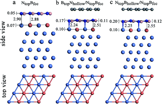
Interestingly, when graphene adsorbs on h-BN/Ni (111)–Cu(50%), the interlayer distances between the h-BN layer and the Ni(111)–Cu(50%) surface are reduced from 2.88Cu/2.90Ni to 2.51Cu/2.24Ni Å for BtopNhollow/NtopBfcc stacking and from 2.88Cu/2.90Ni to 2.55Cu/2.25Ni Å for NtopBhollow/NtopBfcc stacking, as illustrated in Fig. 8, Tables S1 and S2.† The corresponding interaction energies between 1L-Gr/h-BN and the Ni(111)–Cu(50%) surface increase from −0.50 to −0.64 eV per supercell for BtopNhollow/NtopBfcc stacking and from −0.50 to −0.56 eV per supercell for NtopBhollow/NtopBfcc stacking. However, for BtopNhollow/BtopNfcc and NtopBhollow/BtopNfcc stacking in 1L-Gr/h-BN/Ni(111)–Cu(50%) and all other stacking configurations in 1L-Gr/h-BN/Ni(111)–Cu(>50%), Table S1† shows that the interfacial layers become less distorted due to the relatively weak interaction energies and large interlayer distances. Only the topmost layer of the Ni(111)–Cu alloy shows noticeable distortion, in which the Cu atoms move up by about 0.10 Å relative to the Ni atoms in same surface layer, while the h-BN layer is almost unchanged.
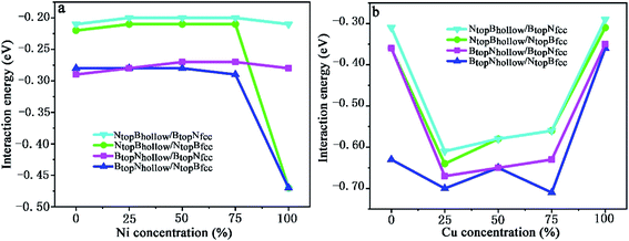 | ||
| Fig. 9 Evolution of the interfacial interaction of 1L-Gr with h-BN/Cu(111)–Ni and h-BN/Ni(111)–Cu surface alloys versus Ni and Cu concentration on the Cu(111)–Ni and Ni(111)–Cu alloy surface. | ||
When the Ni atomic percentage is less than 75% on the Cu(111)–Ni alloy surface, the interaction energy between the graphene layer and h-BN/Cu(111)–Ni surface only depends on the stacking configuration of graphene and the h-BN layers. Fig. 9a shows that the interaction energies between graphene and the h-BN/Cu(111)–Ni surface range from −0.28 to −0.29 eV per supercell for the BtopNhollow/NtopBfcc and BtopNhollow/BtopNfcc stacking, which are slightly higher than those of the NtopBhollow/NtopBfcc and NtopBhollow/BtopNfcc stacking by about 0.06 eV per supercell. For NtopBhollow/NtopBfcc and NtopBhollow/BtopNfcc stacking, the interaction energies between graphene and the h-BN/Cu(111)–Ni surface range from −0.22 to −0.21 eV per supercell, which are comparable with those of L-Gr/h-BN without metal substrates.
When the Ni atomic percentage is higher than 75% on the Cu(111)–Ni alloy surface, the interaction energy between graphene and the h-BN/Cu(111)–Ni surface depends not only on the stacking configuration of the graphene and h-BN, but also on the stacking configuration of h-BN and Cu(111)–Ni. Fig. 9a shows that the interaction energy between graphene and h-BN/Cu(111)–Ni increases sharply from −0.29 to −0.47 eV per supercell for BtopNhollow/NtopBfcc and from −0.21 to −0.47 eV per supercell for NtopBhollow/NtopBfcc stacking as the Ni atomic percentage increases from 75% to 100% on the Cu(111)–Ni alloy surface; this can be attributed to the strong interaction of the NtopBfcc stacking of h-BN and the Cu(111)–Ni surface when the Ni surface atomic percentage is higher than 75%. The interaction energies between graphene and h-BN/Cu(111)–Ni remain at about −0.28 eV per supercell for the BtopNhollow/BtopNfcc stacking and about −0.21 eV per supercell for the NtopBhollow/BtopNfcc stacking due to the weak interaction of BtopNfcc stacking of h-BN with the Cu(111)–Ni surface with a higher Ni surface atomic percentage.
On the Ni(111)–Cu alloy surface, the interaction energies between graphene and the h-BN/Ni(111)–Cu surface are distinctly higher than those of the corresponding freestanding Gr/h-BN. Interestingly, when the Cu atomic percentage is less than 25% on the Ni(111)–Cu alloy surface, Fig. 9b shows that the interaction energies between graphene and the h-BN/Ni(111)–Cu surface increase sharply from −0.31 to −0.61 eV per supercell for NtopBhollow/BtopNfcc stacking, from −0.36 to −0.64 eV per supercell for NtopBhollow/NtopBfcc stacking, and from −0.36 to −0.67 eV per supercell for BtopNhollow/BtopNfcc stacking, while it increases slightly from −0.63 to −0.70 eV per supercell for BtopNhollow/NtopBfcc stacking.
With increasing Cu atomic percentage from 25% to 75% on the Ni(111)–Cu alloy surface, Fig. 9b shows that the interaction energies between the graphene layer and h-BN/Cu(111)–Ni surface decrease linearly from −0.61 to −0.56 eV per supercell for NtopBhollow/BtopNfcc, from −0.64 to −0.56 eV per supercell for NtopBhollow/NtopBfcc and from −0.67 to −0.63 eV per supercell for BtopNhollow/BtopNfcc. The interaction energy of BtopNhollow/NtopBfcc decreases slightly from −0.70 to −0.71 eV per supercell, followed by an increase from −0.65 to −0.71 eV per supercell as the Cu atomic percentage increases from 50% to 75%. However, the interaction energies between graphene and the h-BN/Cu(111)–Ni surface decrease sharply from −0.56 to −0.29 eV per supercell for NtopBhollow/BtopNfcc stacking, from −0.56 to −0.31 eV per supercell for NtopBhollow/NtopBfcc stacking, from −0.63 to −0.35 eV per supercell for BtopNhollow/BtopNfcc stacking and from −0.71 to −0.36 eV per supercell for BtopNhollow/NtopBfcc stacking as the Cu atomic percentage increases from 75% to 100% on the Ni(111)–Cu alloy surface.
The charge density difference of 1L-Gr/h-BN/Cu(111)–Ni and 1L-Gr/h-BN/Ni(111)–Cu is plotted in Fig. S4.† Regarding all the interfaces, the interface between h-BN with Cu(111)–Ni and Ni(111)–Cu substrates shows similar charge transfer and charge accumulation/polarization to that in the h-BN/Cu(111)–Ni and h-BN/Ni(111)–Cu, as shown in Fig. S3.† Furthermore, the interface between the graphene layer and h-BN affords neither charge accumulation nor electron polarization in 1L-Gr/h-BN/Cu(111)–Ni and 1L-Gr/h-BN/Ni(111)–Cu. The results indicate that the adsorption of monolayer graphene on h-BN/Cu(111)–Ni and h-BN/Ni(111)–Cu is physisorption by weak interfacial binding of Pauli exclusion and van der Waals forces, implying that the intrinsic electronic properties of graphene would be completely maintained when growing graphene layers on these h-BN/Cu(111)–Ni or h-BN/Ni(111)–Cu substrates.
4. Discussion
Recent experimental and theoretical studies have indicated that the interfacial interaction strength among graphene, h-BN, and the metal substrate plays important roles in the controllable growth and electronic properties of Gr/h-BN heterostructures.4–6 Experimental studies have reported that Gr/h-BN growth on strongly interacting metal substrates results in the coexistence of perfectly patched Gr/h-BN heterostructures linked with predominant zigzag-type boundaries,6,12 while the Gr/h-BN growth on the weakly binding metal surfaces leads to a hetero-expitaxial growth mechanism of h-BN growth along the graphene edge1 or graphene nucleation at the corners of the triangular h-BN grains.3 It is important to be able to tune the interaction among graphene, h-BN, and the metal surface at different growth stages to achieve controlled growth, which can be achieved through doping metal surfaces to form metal alloys.The intention of this work was to find a general guideline for the selection and tuning of metal surface alloys for controlled growth of Gr/h-BN and also to provide some understanding of the graphene-h-BN-metal interface for potential electronic device design. Thus, we further extended our study to investigate the interfacial structures and interactions of Gr/h-BN layers with the bimetallic Ni/Cu(111) surface alloys, and we focused on the overall interaction among large graphene, h-BN layer and metal surface alloys in addition to the individual steps at different Gr/h-BN growth stages. Our results from the interaction energy, geometric structure, charge transfer, and DOS analyses demonstrate that the interaction strength among graphene, h-BN, and the bimetallic alloy surface can be tuned selectively by reasonably regulating the atomic percentage on the alloy surface. The initially weak interfacial interaction of h-BN/Cu(111) can be enhanced substantially by introducing a Ni surface. In contrast, the initially strong interfacial interaction of h-BN/Ni(111) can be reduced successfully by introducing a Cu surface.
Recently, Lu et al.3 demonstrated successful CVD synthesis of controlled growth of high-quality Gr/h-BN in-plane and stacked heterostructures on Cu–Ni alloy. They verified that the introduction of nickel to a copper substrate not only enhances the catalytic capability of decomposing polyaminoborane residues but also promotes graphene growth via isothermal segregation. Based on the findings from this study, we proposed a new strategy to control growth of high-quality Gr/h-BN, that is, to design surface alloy catalysts by synergetic combination of the distinct catalytic capabilities of Cu and Ni and the well-known segregation phenomenon in Cu/Ni binary alloy. The Ni (Cu) atoms introduced to the surface or subsurface layers of Cu (Ni) substrates can be used as high catalytic activity sites, while the Cu atoms located at the surface or subsurface cam be employed as a favorable segregation medium, such as Cu(111)–Ni–Cu (Ni(111)–Ni–Cu). To facilitate controllable growth of Ge/h-BN, this can be achieved through regulating the atomic percentage and thickness of the Ni–Cu surface layers in the Cu(111)–Ni–Cu or Ni(111)–Ni–Cu surface alloys; therefore, the catalytic capability and isothermal segregation of boron-nitride and carbon species on the Cu(111)–Ni–Cu or Ni(111)–Ni–Cu surface layers cam be changed to provide the desired growth conditions.
5. Conclusions
The evolution of the interface and interaction of the monolayer h-BN and 1L-Gr/h-BN heterostructures on Cu(111)–Ni and Ni(111)–Cu surface alloys versus Ni/Cu atomic percentage were comparatively studied by the DFT-D2 method. For monolayer h-BN on both Cu(111)–Ni and Ni(111)–Cu, the interaction energies of the NtopBfcc/hcp stacking are higher than those of the BtopNfcc/hcp stacking. The interaction energy of h-BN on the Cu(111)–Ni surface increased linearly with increasing Ni atomic percentage for these four stacking configurations. In contrast, the interaction energies of h-BN on Ni(111)–Cu decreased slightly as the Cu atomic percentage increased, except that the interaction energies decreased sharply as the Cu atomic percentage increased from 0% to 50% for the NtopBfcc/hcp stacking. The interlayer distances between h-BN and Cu(111)–Ni decreased gradually with increasing Ni atomic percentage and increased gradually with increasing Cu atomic percentage for h-BN and Ni(111)–Cu.The interaction strength of the 1L-Gr/h-BN heterostructure on Cu(111)–Ni and Ni(111)–Cu followed the order BtopNhollow/NtopBfcc > NtopBhollow/NtopBfcc > BtopNhollow/BtopNfcc > NtopBhollow/BtopNfcc. For both BtopNhollow/NtopBfcc and NtopBhollow/NtopBfcc stacking, the interaction energies of 1L-Gr/h-BN on Cu(111)–Ni increased sharply when the Ni atomic percentage was higher than 75%, while the interaction energies of 1L-Gr/h-BN on Ni(111)–Cu decreased significantly when the Cu atomic percentage was higher than 50%. However, for the NtopBhollow/BtopNfcc and BtopNhollow/BtopNfcc stacking, the interaction energies changed only slightly for 1L-Gr/h-BN on Cu(111)–Ni and Ni(111)–Cu. The interaction energy of graphene on h-BN/Cu(111)–Ni with BtopNhollow stacking were higher than that with NtopBhollow stacking at Ni atomic percentages under 75%, while the interaction energy of graphene on h-BN/Cu(111)–Ni increased sharply at Ni atomic percentages higher than 75% for the NtopBhollow/NtopBfcc and BtopNhollow/NtopBfcc stacking. Differently, the interaction energies between graphene and the h-BN/Ni(111)–Cu surface increased sharply at Cu atomic percentages lower than 25%, while they decreased sharply at Cu atomic percentages higher than 75%. The interaction energies were higher when the percentage of Cu atom was between 25% and 75%. These results suggest that the interfacial interactions and the properties of graphene, h-BN and Cu–Ni alloy can be regulated by tuning the Cu/Ni atomic percentage on the Cu–Ni surface alloys, which provides insight into the epitaxial growth of Gr/h-BN heterostructures and the design of Gr/h-BN-based electronic devices.
Conflicts of interest
The authors declare that there are no conflicts of interest.Acknowledgements
This work is supported by the National Key R&D Program of China (2018YFE0122600), National Natural Science Foundations of China (21373112), China Postdoctoral Science Foundation (2016M591834) and High level talent project of “six talent peaks” in Jiangsu Province (XCL-025). We are grateful to the High Performance Computing Center of Nanjing Tech University for providing the computational resources.References
- L. Liu, J. Park, D. A. Siegel, K. F. McCarty, K. W. Clark, W. Deng, L. Basile, J. C. Idrobo, A. P. Li and G. Gu, Science, 2014, 343, 163–167 CrossRef CAS.
- X. J. Song, T. Gan, Y. F. Nie, J. N. Zhuang, J. Y. Sun, D. L. Ma, J. P. Shi, Y. W. Lin, F. Ding, Y. F. Zhang and Z. F. Liu, Nano Lett., 2016, 16, 6109–6116 CrossRef CAS.
- G. Y. Lu, T. R. Wu, P. Yang, Y. C. Yang, Z. H. Jin, W. B. Chen, S. Jia, H. M. Wang, G. H. Zhang, J. L. Sun, P. M. Ajayan, J. Lou, X. M. Xie and M. H. Jiang, Adv. Sci., 2017, 4, 7 Search PubMed.
- Y. B. Gao, Y. F. Zhang, P. C. Chen, Y. C. Li, M. X. Liu, T. Gao, D. L. Ma, Y. B. Chen, Z. H. Cheng, X. H. Qju, W. H. Duan and Z. F. Liu, Nano Lett., 2013, 13, 3439–3443 CrossRef CAS.
- M. X. Liu, Y. C. Li, P. C. Chen, J. Y. Sun, D. L. Ma, Q. C. Li, T. Gao, Y. B. Gao, Z. H. Cheng, X. H. Qiu, Y. Fang, Y. F. Zhang and Z. F. Liu, Nano Lett., 2014, 14, 6342–6347 CrossRef CAS.
- Y. Qi, N. Han, Y. Li, Z. Zhang, X. Zhou, B. Deng, Q. Li, M. Liu, J. Zhao, Z. Liu and Y. Zhang, ACS Nano, 2017, 11, 1807–1815 CrossRef CAS.
- T. Gao, X. Song, H. Du, Y. Nie, Y. Chen, Q. Ji, J. Sun, Y. Yang, Y. Zhang and Z. Liu, Nat. Commun., 2015, 6, 6835 CrossRef CAS.
- G. H. Han, J. A. Rodriguez-Manzo, C.-W. Lee, N. J. Kybert, M. B. Lerner, Z. J. Qi, E. N. Dattoli, A. M. Rappe, M. Drndic and A. T. C. Johnson, ACS Nano, 2013, 7, 10129–10138 CrossRef CAS.
- J. H. Meng, X. W. Zhang, H. L. Wang, X. B. Ren, C. H. Jin, Z. G. Yin, X. Liu and H. Liu, Nanoscale, 2015, 7, 16046–16053 RSC.
- S. Nappini, I. Pis, T. O. Mentes, A. Sala, M. Cattelan, S. Agnoli, F. Bondino and E. Magnano, Adv. Funct. Mater., 2016, 26, 1120–1126 CrossRef CAS.
- C. Oshima, A. Itoh, E. Rokuta, T. Tanaka, K. Yamashita and T. Sakurai, Solid State Commun., 2000, 116, 37–40 CrossRef CAS.
- R. Drost, S. Kezilebieke, M. M. Ervasti, S. K. Hamalainen, F. Schulz, A. Harju and P. Liljeroth, Sci. Rep., 2015, 5, 8 Search PubMed.
- J. Lu, L. C. Gomes, R. W. Nunes, A. H. Castro Neto and K. P. Loh, Nano Lett., 2014, 14, 5133–5139 CrossRef CAS.
- P. Sutter, Y. Huang and E. Sutter, Nano Lett., 2014, 14, 4846–4851 CrossRef CAS.
- P. Sutter, R. Cortes, J. Lahiri and E. Sutter, Nano Lett., 2012, 12, 4869–4874 CrossRef CAS.
- G. Y. Lu, G. H. Zhang, J. L. Sun, X. J. Wang, Z. Y. Shi, D. Jiang, H. M. Wang, A. Li, T. R. Wu, Q. K. Yu and X. M. Xie, Carbon, 2019, 152, 521–526 CrossRef CAS.
- Q. Wang, P. Liu, X. Bian, J. Huang, W.-q. Li, G.-h. Chen and Y. Yang, Appl. Surf. Sci., 2019, 480, 154–161 CrossRef CAS.
- G. Kresse and J. Furthmuller, Phys. Rev. B: Condens. Matter Mater. Phys., 1996, 54, 11169–11186 CrossRef CAS.
- G. Kresse and D. Joubert, Phys. Rev. B: Condens. Matter Mater. Phys., 1999, 59, 1758–1775 CrossRef CAS.
- P. E. Blochl, Phys. Rev. B: Condens. Matter Mater. Phys., 1994, 50, 17953–17979 CrossRef.
- J. P. Perdew, K. Burke and Y. Wang, Phys. Rev. B: Condens. Matter Mater. Phys., 1996, 54, 16533–16539 CrossRef CAS.
- M. Fuentes-Cabrera, M. I. Baskes, A. V. Melechko and M. L. Simpson, Phys. Rev. B: Condens. Matter Mater. Phys., 2008, 77, 035405 CrossRef.
- J. P. Perdew, K. Burke and M. Ernzerhof, Phys. Rev. Lett., 1996, 77, 3865–3868 CrossRef CAS.
- S. Grimme, J. Comput. Chem., 2006, 27, 1787–1799 CrossRef CAS.
- T. Bucko, J. Hafner, S. Lebegue and J. G. Angyan, J. Phys. Chem. A, 2010, 114, 11814–11824 CrossRef CAS.
- I. Hamada and M. Otani, Phys. Rev. B: Condens. Matter Mater. Phys., 2010, 82, 4 CrossRef.
- M. Vanin, J. J. Mortensen, A. K. Kelkkanen, J. M. Garcia-Lastra, K. S. Thygesen and K. W. Jacobsen, Phys. Rev. B: Condens. Matter Mater. Phys., 2010, 81, 4 CrossRef.
- E. Sanville, S. D. Kenny, R. Smith and G. Henkelman, J. Comput. Chem., 2007, 28, 899–908 CrossRef CAS.
- G. Henkelman, A. Arnaldsson and H. Jonsson, Comput. Mater. Sci., 2006, 36, 354–360 CrossRef.
Footnote |
| † Electronic supplementary information (ESI) available: Total energy, interfacial interaction energy and interlayer vertical distance of the free Gr/h-BN heterostructures, partial densities of state of B and N atoms for free monolayer h-BN, binding energies of h-BN adsorbed on Cu(111)–Ni(100%) in different adsorption geometries versus the distance between h-BN and the Cu(111)–Ni(100%) surface, and charge density difference plots of h-BN on Cu(111)–Ni(25%, 100%), Ni(111)–Cu(25%, 100%). See DOI: 10.1039/d0ra08622c |
| This journal is © The Royal Society of Chemistry 2021 |

