 Open Access Article
Green thin film for stable electrical switching in a low-cost washable memory device: proof of concept†
Naila Arshad‡
a,
Muhammad Sultan Irshad‡ b,
Misbah Sehar Abbasic,
Saif Ur Rehman
 *d,
Iftikhar Ahmed
 e,
M. Qasim Javedf,
Shafiq Ahmad
 g,
Mohamed Sharafg and
Muhammad Dzulqarnain Al Firdausig
aInstitute of Quantum Optics and Quantum Information, School of Science, Xi'an Jiaotong University (XJTU), 710049, P. R. China. E-mail: nailasehar371@gmail.com
bMinistry-of-Education Key Laboratory for the Green Preparation and Application of Functional Materials, School of Materials Science and Engineering, Hubei University, Wuhan 430062, P. R. China. E-mail: sultan.danish93@gmail.com; Tel: +86-156-23138982
cSchool of Energy and Power Engineering, Xi'an Jiaotong University (XJTU), 710049, P. R. China. E-mail: misbahsehar.ms@gmail.com
dClean Energy Technology Research Lab (CERL, ), Department of Physics, COMSATS University Islamabad, Lahore Campus, 54000, Pakistan. E-mail: saifuetian@gmail.com
eEnergy Research Centre, COMSATS University Islamabad, Lahore Campus, 54000, Lahore, Pakistan. E-mail: Iftikhar@live.fr; Tel: +92-321-8856761
fFood and Biotechnology Research Center (FBRC), Pakistan Council of Scientific and Industrial Research, Lahore, 54000, Pakistan. E-mail: Qasim-javed@outlook.com
gDepartment of Industrial Engineering, College of Engineering, King Saud University, Riyadh, Saudi Arabia. E-mail: ashafiq@ksu.edu.sa; mfsharaf@ksu.edu.sa; 438106660@student.ksu.edu.sa
First published on 21st January 2021
Abstract
Low-cost and washable resistive switching (RS) memory devices with stable retention and low operational voltage are important for higher speed and denser non-volatile memories. In the case of green electronics, pectin has emerged as a suitable alternative to toxic metal oxides for resistive switching applications. Herein, a pectin-based thin film was fabricated on a fluorine-doped tin oxide glass substrate for RS mechanism. The presence of sp3–C groups with low binding energy corresponds to tunable charged defects and the oxygen vacancies confirmed by the O 1s spectra that plays a decisive role in the resistive switching mechanism, as revealed by X-ray photoemission spectroscopy (XPS). The surface morphology of the pectin film shows homogeneous growth and negligible surface roughness (38.98 ± 9.09). The pectin film can dissolve in DI water (10 minutes) owing to its ionization of carboxylic groups, that meet the trends of transient electronics. The developed Ag/pectin/FTO-based memory cell exhibits stable and reproducible bipolar resistive switching behavior along with an excellent ON/OFF ratio (104) and negligible electrical degradation was observed over 30 repeated cycles. Hence, it appears to be a valuable application for green electronics. Indeed, biocompatible storage devices derived from natural pectin are promising for high-density safe applications for information storage systems, flexible electronics, and green electronics.
1. Introduction
To fulfill increasing energy demands, exploiting natural resources has become a necessity. In this vein, organic-based devices have aroused research interest owing to their inexpensive manufacturing, low power utilization, pure device fabrication, three-dimensional stacking potential, and multi-state ability for wearable and flexible electronics.1–4 However, the associated cons of noxious inorganic materials make their practical application challenging. In order to cope with this dilemma, the research community has toiled to explore capable nontoxic biomaterials that are eco-friendly, bioresorbable, biodegradable, biocompatible, and can be easily extracted.5–10 Previously, several manufactured optoelectronic devices have been reported using potential biomaterials for write-once and read many times and non-volatile transistor memory applications.11–14 Additionally, resistive switching mechanism-based devices have also been fabricated by employing pectin,15,16 tobacco mosaic virus,17 ferritin protein,18 lime peel,3 2-amino-4,5-imidazoledicarbonitrile (AIDCN)19 and cysteine.20 In 2017, for the first time, Sun et al. introduced pectin as a memristor layer that can be degraded in deionized water in 10 minutes, but the high operational voltage needs some improvement.15 In the same year, Kozicki and Valov reported the use of organic material to prepare biocompatible, low-cost, and bio-electronic cell-based memristors.21,22 Moreover, surface roughness also plays a decisive role in preventing undesired current paths that may lead to unstable conduction filaments and high operational voltage.3 In this contribution, various in situ experiments were carried out to minimize current leakage or prevent undesired current paths via surface defect engineering and the introduction of localized point defects within the insulating layer. These point defects act like a hopping charge carrier, minimize the leakage factor and provide a smooth tunable conductive path.23 He et al. observed bipolar resistive switching in an organometallic framework using a nanocluster layer. The observed mechanism initiates as a result of the oxidation of a silver metal top electrode and the incorporation of an organic layer forming a tunable conduction current channel.24 The reduction of an active metal electrode (Ag1+ ions) towards the bottom electrode enabled the formation of a localized conduction bridge inside the dielectric layer, which provides a current path from the top electrode to the bottom electrode; referred to as electrochemical metallization (ECM) or conduction bridge RAM (CBRAM). More interestingly, double negatively charged oxygen vacancies promote trap-filled phenomena and enhance the stability of the conduction bridge filament.25,26 As a result of the organometallic framework, it has been concluded that biomaterials follow a simple, eco-friendly, low-cost fabrication process to produce memristor devices with low leakage factor and a stable conduction filament.Citrus fruits are widely used all over the world for fresh juice and packed beverages. However, fortuitously, orange peel, a by-product that makes up half of an orange's weight, is an enriched source of pectin27,28. Pectin is a negatively charged colloid in an acid fruit substrate. It is derived from protopectin, which is a high-molecular-weight carbohydrate polymer found in the lamellae of virtually all plant cells, where it contributes to the cell structure.5,29–31 Recently, pectin has received deep research interest in various areas owing to its superior bioactivity and ionicity.31 Xu et al.32 and Hao et al.33 established a pectin-based memristor and a flexible temperature sensor. In this contribution, we have extracted pectin from orange peel without any chemical reagents by utilizing the method followed by Sun et al. and Xu et al.15,32 The pectin thin film was fabricated on commercially available fluorine-doped tin oxide (FTO) glass for the memristor device. The 300 nm thick pectin film shows negligible surface roughness, outstanding ON/OFF ratio, and stable tunable bipolar resistive switching under a low voltage regime without any electrical deterioration. The carboxylic compound-based chemical composition of pectin enables its transient ability for green electronics that can be degraded in deionized water in just 10 minutes. Moreover, the detailed XPS scans reveal the presence of sp3–C groups in the C 1s spectra, confirming the presence of tunable charged defects in the pectin structure, while the O 1s spectra exposed the oxygen vacancy peak that leads to switching mechanisms and facilitates the oxidation of silver ions. Pectin-based devices tend to be compatible with biomedical, electronic, chemical, and physical applications. Thus, the fabricated device was characterized extensively using various techniques and was found to have excellent switching properties and reliability.
2. Experimental section
2.1 Raw materials and reagents
Oranges (Citrus reticulata) acquired from regional orchard fruit were peeled, then the peel was chopped and allowed to dry in a hot air oven at a temperature of 55–60 °C until a constant weight was obtained.16,32 Afterward, the peels were ground and passed through a 40-mesh sieve to produce powdered peel. The dried orange peel powder was then stored in receptacles in a dry atmosphere until require. All chemicals and solvents utilized during this experiment were of analytical grade and were obtained from Sigma Aldrich.2.2 Extraction of pectin from dried orange peel
A typical microwave oven with an operating frequency of 2450 MHz with varying time and power was employed to extract the pectin from the dried peel powder. Dried peel powder (1 g) was added as the solute in a beaker containing distilled water as the solvent at various pH values (1, 1.5, 2). The pH of the water was modified by the addition of sulfuric acid (0.05, 0.016, and 0.005 mol J−1). The extraction was achieved under discrete conditions. The beaker was placed in the center of the oven over the rotary dish. The beaker was heated by exposing it to microwave radiation with distinct power levels (160, 320, 480 W) and irradiation times (60, 120, 180 s). The obtained mixture was allowed to cool down to room temperature and then decontaminated using filter paper. Subsequently, the filtered extract was centrifuged and the supernatant was precipitated with an equal volume of 95% ethanol. Finally, to obtain pectin free of mono- and di-saccharides, the extract was washed with 95% ethanol.2.3 Preparation of Ag/pectin/FTO devices
At room temperature, a spin coating method (3000 rpm) was utilized for the deposition of the pectin film on the FTO substrate. Toluene was used to make a slurry for the deposition of the pectin thin film on the FTO substrate. After the deposition of the pectin film on the FTO substrate, the sample was dried at 60 °C for 12 h to eliminate toluene. Finally, the top electrode of Ag paste with an area of 1.2 mm2 was deposited to achieve a device containing Ag/pectin/FTO in a sandwich structure.The complete process of the extraction of pectin from orange peel and the deposition of the pectin film is described in Fig. 1. Moreover, the characterization tools and characteristics are detailed in the ESI (Note SI†).
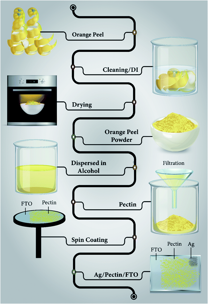 | ||
| Fig. 1 Schematic illustration showing the extraction of pectin from orange peel and the complete procedure of coating the pectin film on the FTO substrate. | ||
3. Results and discussion
3.1 Compositional analysis of pectin
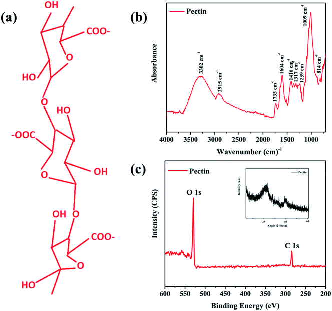
Pectins are heterosaccharides formed from complex chains of monosaccharide units. The characteristic structure of pectin is a linear chain of α (1 → 4) linked D-galacturonic acid that forms the homogalacturonan backbone31. In order to determine the structural composition and surface elemental impact in detail, the prepared pectin film was further characterized by X-ray diffraction, X-ray photoelectron spectroscopy (XPS), and Fourier transform infrared spectroscopy (FT-IR).Fig. 2a shows the polymeric chains of pectin and its hydrophilic nature.15 The structure features a linear chain of α (1 → 4) linked D-galacturonic acid that is a building block of monosaccharide units (C–OH and C–O–C groups).31,34 FTIR spectroscopy confirmed the existence of these side groups with stretching bands at 814, 1009, and 1239 cm−1 that correspond to C–OH side groups and the C–O–C glycosidic bond vibration, as illustrated in Fig. 2b. Absorption peaks between 1100 and 1200 cm−1 correspond to ether R–O–R and cyclic C–C bonds in the ring structure of pectin. The fingerprint region between 1200 cm−1 and 950 cm−1 corresponding to carbohydrates, which was found in the overlay spectra of pectin and mixed pectin polymer films, confirmed the presence of natural polysaccharides in the developed film (Manrique & Lajolo, 2002).35 The bands at 1604 and 1733 cm−1 are attributed to free and esterified carboxyl groups, respectively. The band at 2915 cm−1 corresponds to methyl group stretching from the methyl esters of galacturonic acid. The broader band at 3302 cm−1 appears due to the stretching of hydroxyl groups caused by the moisture in the pectin.34,35 Fig. 2c presents the XPS and XRD results and confirms the basic elemental composition of the pectin structure, including carbon and oxygen vacancies.
The XPS spectrum contained only two peaks at 280.0 and 530.0 eV, representing the C 1s and O 1s orbital orientation, respectively, which confirms that the prepared sample is pure pectin based on the presence of C and O elements without further impurities attached. The O 1s peak indicates the presence of oxygen vacancies in the pectin film. These oxygen vacancies play a vital role as hopping charge carriers within the pectin layer and also facilitate the migration of Ag ions to form a stable conduction filament.15,32 Moreover, the XRD results (inset) provide further confirmation of the XPS results by presenting just two carbon peaks at 19.3° and 42.1°, which confirm the absence of any other impurities.
3.2 Pectin's electronic structure and oxygen vacancies
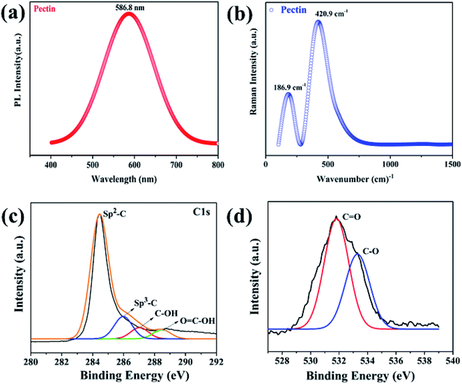
PL spectroscopy is a powerful non-destructive tool that can be used to identify the intrinsic defects of pectin-based thin films, such as point defects, lattice defects, or deep level impurities, which could occur during material synthesis, such as oxygen vacancies.18,36–38 Fig. 3a presents the PL spectrum of the pectin film. It is obvious from the spectrum that pectin film shows only one sharp intensity peak in the visible region (yellow) at 586.8 nm, which corresponds to a 2.11 eV optical bandgap. The single peak without any shoulder peak indicates the pure quality of the pectin without any lattice or interstitial defects.11,18–20,32After the recombination of electron and hole pairs via π → π* transitions in the visible region (yellow), possibly due to oxygen vacancies or due to loosely held transition electrons in carbon.16,39,40 Raman spectroscopy was also used to investigate the vibration modes of the pectin film.16,38 The prepared thin film was analyzed by Raman spectroscopy in the range of 0 to 1500 cm−1, as shown in Fig. 3b.
Two Raman bands were detected for the pectin film at 180 cm−1 and 423 cm−1. The peak at 180 cm−1 was attributed to the stretching of the C–OH bond, affirming the presence of the pectin backbone.15,32 The second peak at 423 cm−1 represents the stretching of the C–O–C bond, indicating the presence of the glycosidic bond in pectin. These bands are attributed to the π → π* transition in the visible region, which supports the PL emissions findings.34 In such electronic transitions, electrons are superimposed with other molecular energy states.19,30,34 Thus, these are generally broad transitions rather than a narrow band. The presence of two bands in the prepared samples indicates the presence of an enhanced number of organic compounds associated with oxygen vacancies in pectin, providing opportunities for the migration of metal ions for the resistive switching mechanism. Detailed XPS scans were also performed to analyze the chemical composition and ensure the presence of oxygen vacancies in the pectin film. Fig. 3c presents the C 1s spectra of the pectin film and reveals four main peaks corresponding to sp2–C, sp3–C, C–OH, and O![[double bond, length as m-dash]](https://www.rsc.org/images/entities/char_e001.gif) C–OH groups at 284.5, 285.8, 287.9, and 288.6 eV respectively. The lower binding energy of sp3–C compared to sp2–C confirmed the presence of charge defects in the pectin film. Fujimoto et al. briefly investigated these charge defects, i.e. oxygen vacancies and interstitial defects, that originate due to the presence of sp3–C.41 Moreover, the presence of oxygen vacancies was also confirmed through the O 1s spectra, as shown in Fig. 3d. The O 1s spectra show two major peaks: an oxygen vacancy peak at 531 eV that is linked with bulk surface carbon species (C
C–OH groups at 284.5, 285.8, 287.9, and 288.6 eV respectively. The lower binding energy of sp3–C compared to sp2–C confirmed the presence of charge defects in the pectin film. Fujimoto et al. briefly investigated these charge defects, i.e. oxygen vacancies and interstitial defects, that originate due to the presence of sp3–C.41 Moreover, the presence of oxygen vacancies was also confirmed through the O 1s spectra, as shown in Fig. 3d. The O 1s spectra show two major peaks: an oxygen vacancy peak at 531 eV that is linked with bulk surface carbon species (C![[double bond, length as m-dash]](https://www.rsc.org/images/entities/char_e001.gif) O) present in the pectin structure and a second peak at 533.3 eV corresponding to C–O groups.
O) present in the pectin structure and a second peak at 533.3 eV corresponding to C–O groups.
3.3 Pectin's morphology and surface roughness
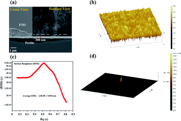
The surface morphology and the cross-sectional thickness along the texture profile of the pectin film were examined by field emission scanning electron microscopy (FESEM) and atomic force microscopy (AFM). The pectin film exhibits a bumpy and dense morphology and a closely packed surface that relates to heterogeneous growth with a negligible gap, as illustrated in Fig. 4a (surface view). The bumpy surface agglomerates may be due to the crystalline cellulosic stress of carboxylic groups present in pectin. The aggregation of the surface of the pectin film can be explored more convincingly by comparison with natural cellulose xanthate (CX) biomaterial-based thin film,1,39 which shows that the pectin thin film exhibits regular growth with a uniform pattern. Moreover, cross-sectional FESEM analysis was also carried out to investigate the pectin film thickness on the FTO substrate. Fig. 4a (cross-sectional view, inset) depicts the uniform 300 nm pectin film thickness deposited on the FTO substrate. Indeed, the uniform surface morphology along the thickness plays a crucial role in the stability of the conduction filament and avoids undesired current channels3,16,42. The thickness-dependent characteristics significantly enhance the oxygen vacancies.23,43,44 Myoung et al. reported oxygen vacancy-related thickness-dependent characteristics in ZnO thin films.43Contarary to the results of Sun et al. (500 nm),15 our fabricated pectin film (300 nm) demonstrates less than 200 nm thickness difference, which signifies the abundant concentration of oxygen vacancies. More oxygen vacancies lead to more stability in the conduction filament or resistive switching.23,37,45 Furthermore, surface defects and roughness also play a decisive role in the leakage of the current or undesired current path.3,16,42 If the number of surface defects and the surface roughness is high, then there is the possibility of the uncontrolled diffusion of the top electrode ions.46,47 In order to avoid uncontrolled or undesired current channels, the surface roughness should be significantly minimized.32,43,46,47
In this contribution, the prepared pectin film texture was examined via a well-known AFM technique. Fig. 4b shows a 3D texture view of as-prepared pectin film. The demonstrated structure revealed the heterogeneous bumpy and dense morphology of the pectin film. The observed bumps are mainly the same in nature and appear as a uniform surface texture. The overall texture exhibits a closely packed surface without any gaps. Owing to its uniform texture, the surface roughness is surprisingly negligible and was estimated using the well-renowned Gwyddion software, as demonstrated in Fig. 4c. The estimated root mean square (RMS) surface roughness is about 38.98 ± 9.09 nm for a selected area of 250 × 250 μm2. Additionally, the slope distribution of the pectin film texture is also presented in Fig. 4d. The observed root mean square (RMS) surface roughness (38.98 ± 9.09 nm) emerged due to the adhesion stress between the pectin film and the FTO substrate. The phase topography also depicts the closely packed deposition of the pectin film, as illustrated in the ESI (Fig. S1†). The desired thickness (300 nm) and negligible surface roughness of the pectin film make it a suitable candidate for resistive switching applications.
3.4 Pectin-based memory cell
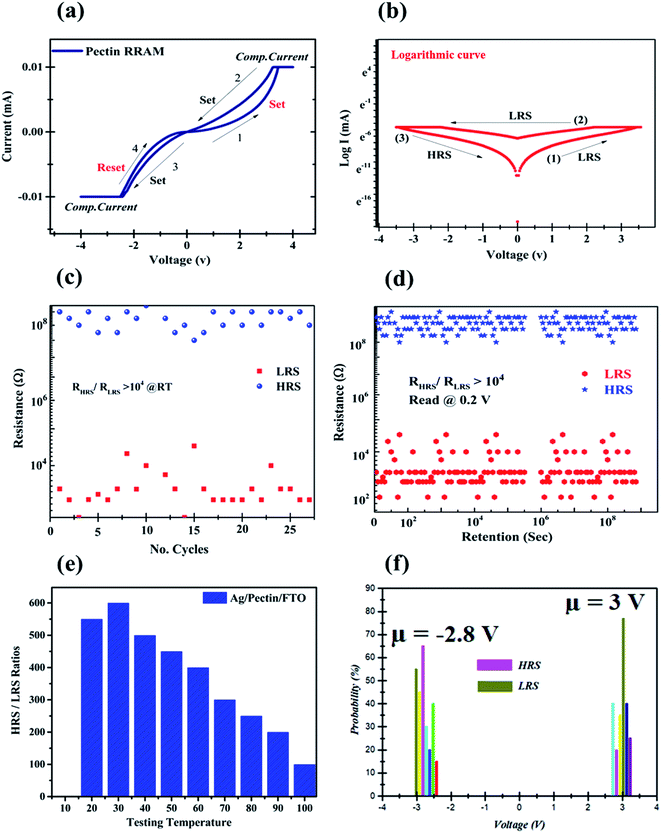
Recently, several studies have shown great potential in biomaterial-induced memristor devices.17–20,24,32 In 2020, our group also reported a lime peel-derived TiO2 3D flower-based thin film3 for RRAM and is also keenly interested in the possibility of a carbohydrate-based system for resistive memory applications. In this contribution, a 300 nm pectin film-based RRAM cell was fabricated for resistive switching behavior. The experimental setup to examine resistive switching characteristics in the pectin film is illustrated in a schematic illustration in Fig. 1, in which Ag and FTO act as the top and bottom electrodes, respectively. The typical current–voltage (I–V) response of the Ag/pectin/FTO RRAM cell was determined to test the reliability of pectin during resistive switching behavior. During the electroforming of the conduction filament, a low compliance current (CC) of 0.01 mA was applied to avoid the permanent dielectric breakdown of the natural organic material.16,32 The electroforming graph is provided in the ESI (Fig. S2†). From Fig. 5a, the asymmetric behavior of the typical I–V characteristic curves of Ag/pectin/FTO on a linear scale is an obvious hysteresis loop. Moreover, further declaration of permanent resistive switching is clear from Fig. 5b on the logarithmic scale. By sweeping the voltage from 0 V to 4 V (sweep 1), the Ag/pectin/FTO RRAM cell behaved linearly up to 2 V and suddenly switched into low resistance state (LRS) at 3 V accompanied by the enhancement of the current from 1 mA to 10 mA. The pectin memory cell switched into the set state (ON) at 3 V, which corresponds to sweep 1. In the second sweep (4 V → −4 V), the pectin memory device stayed in LRS owing to its asymmetric or bipolar nature. In the reverse period (4 V → 0 V), the memory cell remained in LRS up to −2 V but abruptly switched into HRS at −2.8 V, which corresponds to the reset state (OFF). The switching from LRS to HRS at a specific voltage (−2.8 V) confirmed the asymmetric nature of the pectin memory cell. In order to address this dilemma, the research community has toiled to explore nontoxic biomaterials that are eco-friendly, bioresorbable, biodegradable, and can be easily extracted.The fabricated pectin-based memristor demonstrates an explicit bipolar, fast conversion resistive switching behavior with excellent reproducibility. In short, the findings are equivalent to a resistive system based on protein and other pectin-based memristor devices.17,18,20,24,32 It affirms that the Ag/pectin/FTO memory cell has two stable resistance states that correspond to the resistive memory switching effect under the application of the electric field. The observed switching behavior showed a sudden rise in the current at a specific voltage of about 3 V (VSet); a variation from the high-resistance state (HRS) or “OFF” state to the low resistance state (LRS) or “ON” state “set” process is achieved.
The “reset” cycle from an LRS or “ON” state reverts to the “HRS” or “OFF” state in applied voltage, as the applied voltage sweeps from negative to zero voltage at about −2.8 V (VReset). The two well-resolved states provide a simple memory window for resistance switching devices.23,37 The pectin-based memory window offers various logic states to read and write data bits and demonstrates great potential for non-volatile memory applications.
Fascinatingly, the memristor behavior of the pectin RRAM cell is almost the same in terms of HRS and LRS stability after 30 consecutive cycles. The endurance test for Ag/pectin/FTO showed no electrical degradation, as illustrated in Fig. 5c. Besides that, the pectin memory cell shows an outstanding window size or ON/OFF ratio (104) during the cycle retention test over 108 seconds, as shown in Fig. 5d. Both states are obviously stable during the consecutive 108 seconds, which confirms the non-volatile and non-destructive readability of the system. Indeed, keeping in mind pectin's organic nature, the temperature-dependent memristor behavior was also verified.
Fig. 5e shows the memristor behavior of the pectin memory cell at different temperatures and shows that the maximum stability in the resistance window is sustained at 30 °C. The reduction in the resistance ratio emerged due to the leakage of current into an undesired path owing to the thermal decomposition of carboxylic groups. However, the statistical voltage distribution (SVD) function was also determined to comprehend the Vset and Vreset states efficiently, as illustrated in Fig. 5f. The results above demonstrate the potential for resistive non-volatile memory switching applications through the constant resistive switching of the Ag/pectin/FTO system.
The I–V curve for the first sweep in the positive and negative voltage regions for the Ag/pectin/FTO device was plotted on a log–log scale to confirm the conduction and switching mechanisms of the device. For the positive and negative areas of Fig. 6a and b, the linear fit slope is approximately 0 to 1.03 V and 0 to 1.06 V, clearly indicating the ohmic conductance behavior. The conduct response in the OFF state is difficult to analyze comparatively and switched at −2.8 V as illustrated in Fig. 6b (Table 1).
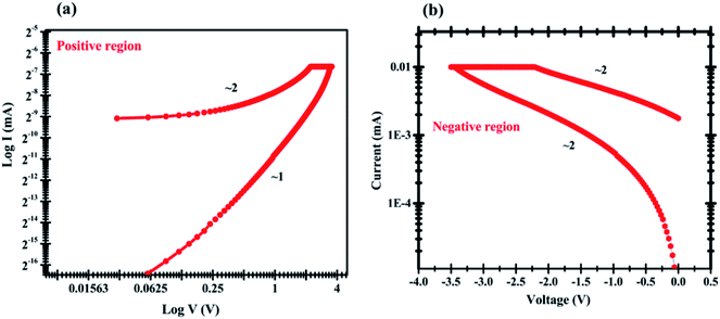 | ||
| Fig. 6 log–log scale fitting of I–V curve of pectin memory cell where the scattering points denote experimental findings for both the (a) positive region and (b) negative region. | ||
| Sr. no | Film material | Thickness | Vset/Vreset, voltage (V) | ON/OFF ratio | Endurance (cycles)/retention (s) | Ref. |
|---|---|---|---|---|---|---|
| 1 | Ag/pectin/FTO | 500 nm | 3.3 V/−4.3 V | 450 | 100/500 | 15 |
| 2 | Ag/orange peel/FTO | NA | 1.3 V/−1.6 V | 103 | 50/1000 | 16 |
| 3 | Ag/pectin/ITO | 300 nm | 1.1 V/−0.5 V | NA | 104/>104 | 32 |
| 4 | Al/AP/ITO | 40 nm | 2 V/−2.1 V | 107 | NA/105 | 48 |
| 5 | Ag/pectin/FTO | 300 nm | 3 V/−2.8 V | 104 | 30 cycles, >108 | This work |
The injected carrier density is smaller for the positive area in the low voltage region (0–1.33 V) than that of the thermally induced carrier density, thus current is dependent on the field and on the material conductivity, which represents the ohmic response of the device. The conduction activity in the high voltage region (1.03–3 V) follows the classical trap-controlled space-charge-limited conduction model (SCLC).23,37 It can be explained by the possibility of defects inside the pectin forming trap-sites under the conduction band that can trap the injected load carriers.15 The chemical structure of pectin includes a carboxylic unit, an amine connection and a carbonyl group, which act as nucleophilic or electrophilic locations and may lead to some trap sites.30–32 When the voltage increases from ∼3 V, any trap available is filled and the current rises abruptly, turning the OFF state into the ON state, as illustrated in Fig. 6a. The ohmic activity of the Ag/pectin/FTO unit in both ON and OFF modes is described by the following eqn (1):
 | (1) |
Sun et al. also reported the same conduction mechanism in pectin-based thin films where active metal ions combined with oxygen vacancies for resistive switching behavior.15 Our fabricated pectin film, owing to its slightest surface roughness (38.98 ± 9.09 nm) and desired thickness (300 nm), possesses more oxygen vacancies as confirmed by XPS and XRD investigations. We believe that the observed switching mechanism in the Ag/pectin/FTO RRAMs is purely based on hopping charge carriers (oxygen vacancies) and active silver ions that are accountable for the conduction filament model. Notably, the carboxylic composition of the pectin layer may facilitate the migration of Ag1+ ions and their combination with oxygen vacancies to form a conducting path between two electrodes.
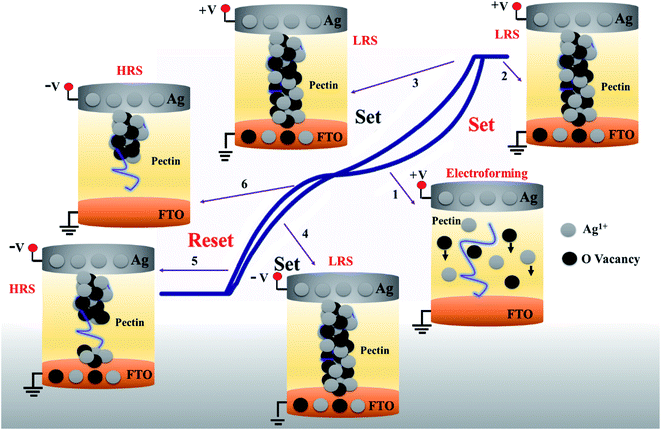
A comprehensive schematic illustration of switching from electroforming to set/reset states is presented in Fig. 7. Under the influence of a sufficient electric field, active Ag metal could easily be oxidized into Ag1+ ions, which could be described as Ag → Ag1+ + e−1. Ag1+ ions start drifting along the direction of the electric field, whereas the pectin molecular chain plays the role of the mobile channel for Ag1+ ions and oxygen vacancies present in the pectin layer attributed to the electroforming process, as shown in Fig. 7 (arrow-1).
The conductivity of the material will increase dramatically as Ag1+ ions and oxygen vacancies accumulate to a certain level. At a certain threshold stimulus (3 V), the combination of oxygen vacancies and Ag1+ ions enabled the CF formation or “set” state as schematized in Fig. 7 (arrow 2). The compliance current sustained the dielectric behavior of pectin. The stable “set” state maintained its bipolar or asymmetric nature in the second sweep, as illustrated in Fig. 7 (arrows 3 and 4). After the “set” process, the state is sustained by the device until the application of sufficient voltage of opposite polarity or <VRse to dissolve the filaments electrochemically to “reset” the device at −2.8 V, along with the drifting of Ag1+ ions and oxygen vacancies by electric field back to the top electrode as demonstrated in Fig. 7 (arrows 5 and 6). Hence, the formation and rupture of conductive filaments are purely dependent on hopping charge carriers or oxygen vacancies with the aid of highly active Ag1+ ions in the Ag/pectin/FTO-based memory cell. The proposed mechanism will inspire further research in transient green electronics applications.
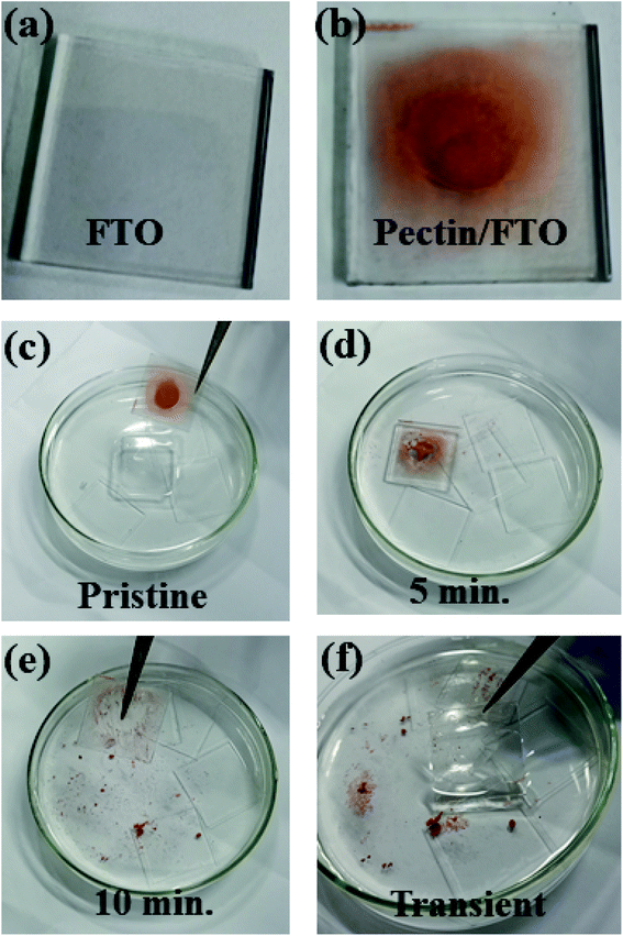
Pectin was also assessed to ensure its transient nature as an eco-friendly memory device. For this, the functional pectin film was immersed in deionized water (DI) at room temperature (25 °C) for 10 minutes. The film dissolution process was recorded in the form of evolution images, as illustrated in Fig. 8a–f. The evolution images demonstrate the rapid dissolution of pectin and it vanished completely from the FTO substrate after 10 minutes in DI water. The complete pectin dissolution reveals no resistive switching response and the obtained FTO glass could be reused. The presence of carboxylic groups is responsible for the transient nature and enables pectin to dissolve easily in DI water.
4. Conclusions
In summary, a low-cost biomaterial-inspired and transient pectin thin film was successfully fabricated for memristor devices. The surface morphology of the prepared pectin film showed negligible surface roughness (38.98 ± 9.09 nm) and the desired thickness (300 nm), making it suitable for stable and reproducible resistive switching applications. The detailed characterization of the pectin film confirmed the existence of point defects such as oxygen vacancies, which combined with Ag1+ ions play a significant role in accomplishing the conduction filament mechanism in the pectin dielectric layer. The DC resistivity measurement of the Ag/pectin/FTO cell exhibited bipolar resistive switching behavior under a low voltage regime (set/reset, 3 V/−2.8 V) accomplished with 0.01 mA compliance current. Both states can be reproduced without causing any electrical degradation over 30 successive switching cycles, e.g., retention (108 seconds). The obtained results show that the Ag/pectin/FTO device possesses excellent resistive switching memory phenomena, which enables this device to record data in its respective HRS and LRS and makes it a potential candidate for use in transient non-volatile memory devices in the future.Author contributions
All authors significantly contributed to the manuscript.Conflicts of interest
The authors declare no conflict of interest.Acknowledgements
The authors extend their appreciation to the Deanship of Scientific Research at King Saud University for funding this work through research group no (RG-1438-089).References
- M. Weißl, M. A. Hobisch, L. S. Johansson, K. Hettrich, E. Kontturi, B. Volkert and S. Spirk, Cellulose, 2019, 26, 7399–7410 CrossRef.
- R. S. Orozco, P. B. Hernández, G. R. Morales, F. U. Núñez, J. O. Villafuerte, V. L. Lugo, N. F. Ramírez, C. E. B. Díiaz and P. C. Vázquez, BioResources, 2014, 9, 1873–1885 Search PubMed.
- M. S. Abbasi, M. S. Irshad, N. Arshad, I. Ahmed, M. Idrees, S. Ahmad, Z. Wei, M. Sharaf and M. D. Al Firdausi, ACS Omega, 2020, 5(30), 19050–19060 CrossRef CAS.
- I. Valov, E. Linn, S. Tappertzhofen, S. Schmelzer, J. van den Hurk, F. Lentz and R. Waser, Nat. Commun., 2013, 4, 1771 CrossRef CAS.
- M. S. Irshad, M. H. Aziz, M. Fatima, S. U. Rehman, M. Idrees, S. Rana, F. Shaheen, A. Ahmed, M. Q. Javed and Q. Huang, Mater. Res. Express, 2019, 6, 0950a4 CrossRef CAS.
- N. I. Lebovka, I. Praporscic, S. Ghnimi and E. Vorobiev, J. Food Eng., 2005, 69, 177–184 CrossRef.
- Z. Cserhalmi, A. Sass-Kiss, M. Tóth-Markus and N. Lechner, Innovative Food Sci. Emerging Technol., 2006, 7, 49–54 CrossRef CAS.
- A. Kowittaya and S. Asavasanti, in International congress on food engineering and technology (IFET2012), 2012, pp. 26–28 Search PubMed.
- O. Korbut, M. Bučková, J. Labuda and P. Gründler, Sensors, 2003, 3, 1–10 CrossRef CAS.
- J. Juansah, I. W. Budiastra, K. Dahlan and K. B. Seminar, Int. J. Food Prop., 2014, 17, 1498–1517 CrossRef CAS.
- H. D. Pham, L. Xianqiang, W. Li, S. Manzhos, A. K. K. Kyaw and P. Sonar, Energy Environ. Sci., 2019, 12, 1177–1209 RSC.
- P. Arunkumar, Y. H. Kim, H. J. Kim, S. Unithrattil and W. Bin Im, ACS Appl. Mater. Interfaces, 2017, 9, 7232–7240 CrossRef CAS.
- S. Chen and G. Shi, Adv. Mater., 2017, 29, 1605448 CrossRef.
- H. Choi, J. S. Park, E. Jeong, G.-H. Kim, B. R. Lee, S. O. Kim, M. H. Song, H. Y. Woo and J. Y. Kim, Adv. Mater., 2011, 23, 2759–2763 CrossRef CAS.
- B. Sun, X. Zhang, G. Zhou, P. Li, Y. Zhang, H. Wang, Y. Xia and Y. Zhao, Org. Electron., 2017, 42, 181–186 CrossRef CAS.
- X. Wang, S. Tian, B. Sun, X. Li, B. Guo, Y. Zeng, B. Li and W. Luo, Chem. Phys., 2018, 513, 7–12 CrossRef CAS.
- R. J. Tseng, C. Tsai, L. Ma, J. Ouyang, C. S. Ozkan and Y. Yang, Nat. Nanotechnol., 2006, 1, 72–77 CrossRef CAS.
- H. Wang, F. Meng, B. Zhu, W. R. Leow, Y. Liu and X. Chen, Adv. Mater., 2015, 27, 7670–7676 CrossRef CAS.
- Y. Nakayama, Y.-H. Huang, C.-H. Wei, T. Kubo, S. Machida, T.-W. Pi, S.-J. Tang, Y. Noguchi and H. Ishii, J. Appl. Phys., 2010, 108, 53702 CrossRef.
- J.-W. Choi, B.-K. Oh, Y. J. Kim and J. Min, Appl. Phys. Lett., 2007, 91, 263902 CrossRef.
- I. Valov and M. Kozicki, Nat. Mater., 2017, 16, 1170–1172 CrossRef CAS.
- A. Fujimoto, Y. Yamada, M. Koinuma and S. Sato, Anal. Chem., 2016, 88, 6110–6114 CrossRef CAS.
- R. Waser and M. Aono, in Nanoscience And Technology: A Collection of Reviews from Nature Journals, World Scientific, 2010, pp. 158–165 Search PubMed.
- J. He, L. Ma, J. Wu and Y. Yang, J. Appl. Phys., 2005, 97, 64507 CrossRef.
- I. Valov, E. Linn, S. Tappertzhofen, S. Schmelzer, J. van den Hurk, F. Lentz and R. Waser, Nat. Commun., 2013, 4, 1771 CrossRef CAS.
- I. Valov and M. Kozicki, Nat. Mater., 2017, 16, 1170–1172 CrossRef CAS.
- M. A. Anagnostopoulou, P. Kefalas, V. P. Papageorgiou, A. N. Assimopoulou and D. Boskou, Food Chem., 2006, 94, 19–25 CrossRef CAS.
- K. E. Malterud and K. M. Rydland, J. Agric. Food Chem., 2000, 48, 5576–5580 CrossRef CAS.
- M. Cháfer, C. González-Martínez, A. Chiralt and P. Fito, Food Res. Int., 2003, 36, 35–41 CrossRef.
- D. Mohnen, Curr. Opin. Plant Biol., 2008, 11, 266–277 CrossRef CAS.
- A. N. Round, N. M. Rigby, A. J. MacDougall and V. J. Morris, Carbohydr. Res., 2010, 345, 487–497 CrossRef CAS.
- J. Xu, X. Zhao, Z. Wang, H. Xu, J. Hu, J. Ma and Y. Liu, Small, 2019, 15, 1803970 CrossRef.
- L. Hao, J. Ding, N. Yuan, J. Xu, X. Zhou, S. Dai and B. Chen, Org. Electron., 2018, 59, 243–246 CrossRef CAS.
- P. Opanasopit, A. Apirakaramwong, T. Ngawhirunpat, T. Rojanarata and U. Ruktanonchai, AAPS PharmSciTech, 2008, 9, 67–74 CrossRef CAS.
- L. Liu, J. Cao, J. Huang, Y. Cai and J. Yao, Bioresour. Technol., 2010, 101, 3268–3273 CrossRef CAS.
- S. A. Abdullah, M. Z. Sahdan, N. Nafarizal, H. Saim, A. S. Bakri, C. H. C. Rohaida, F. Adriyanto and Y. Sari, J. Phys.: Conf. Ser., 2018, 995, 12067 CrossRef.
- L. Zhu, J. Zhou, Z. Guo and Z. Sun, Journal of Materiomics, 2015, 1, 285–295 CrossRef.
- L. J. Larson, K.-S. K. Shin and J. I. Zink, J. Am. Inst. Conserv., 1991, 30, 89–104 CrossRef.
- H. S. Mohapatra, A. Chatterjee and P. Kumar, Tekstilec, 2015, 58, 268–273 CrossRef CAS.
- S.-X. Chen, S.-P. Chang, S.-J. Chang, W.-K. Hsieh and C.-H. Lin, ECS J. Solid State Sci. Technol., 2018, 7, Q3183 CrossRef CAS.
- A. Fujimoto, Y. Yamada, M. Koinuma and S. Sato, Anal. Chem., 2016, 88, 6110–6114 CrossRef CAS.
- M. S. Irshad, A. Abbas, H. H. Qazi, M. H. Aziz, M. Shah, A. Ahmed and M. Idrees, Mater. Res. Express, 2019, 6, 76311 CrossRef CAS.
- Y. H. Kang, J.-H. Choi, T. Il Lee, W. Lee and J.-M. Myoung, Solid State Commun., 2011, 151, 1739–1742 CrossRef CAS.
- K. D. Bhalerao, E. Eteshola, M. Keener and S. C. Lee, Appl. Phys. Lett., 2005, 87, 143902 CrossRef.
- P. A. N. Feng, C. Chao, Z. Wang, Y. Yang, Y. Jing and Z. Fei, Prog. Nat. Sci.: Mater. Int., 2010, 20, 1–15 CrossRef.
- J. Robertson and R. Gillen, Microelectron. Eng., 2013, 109, 208–210 CrossRef CAS.
- B. J. Choi, D. S. Jeong, S. K. Kim, C. Rohde, S. Choi, J. H. Oh, H. J. Kim, C. S. Hwang, K. Szot, R. Waser and Others, J. Appl. Phys., 2005, 98, 33715 CrossRef.
- Y.-C. Chang, J.-C. Jian, M.-Y. Chuang, Y. L. Hsu, W.-Y. Huang and S.-J. Young, ACS Appl. Electron. Mater., 2020, 2(9), 2798–2805 CrossRef CAS.
- N. Raeis-Hosseini and J.-S. Lee, J. Electroceram., 2017, 39, 223–238 CrossRef CAS.
- B. Mu, H.-H. Hsu, C.-C. Kuo, S.-T. Han and Y. Zhou, J. Mater. Chem. C Search PubMed.
- Y. Qi, B. Sun, G. Fu, T. Li, S. Zhu, L. Zheng, S. Mao, X. Kan, M. Lei and Y. Chen, Chem. Phys., 2019, 516, 168–174 CrossRef CAS.
- Z. Lv, Y. Zhou, S.-T. Han and V. A. L. Roy, Mater. Today, 2018, 21, 537–552 CrossRef CAS.
- L. Zheng, B. Sun, S. Mao, S. Zhu, P. Zheng, Y. Zhang, M. Lei and Y. Zhao, ACS Appl. Bio Mater., 2018, 1, 496–501 CrossRef CAS.
- Z. Lv, Y. Wang, Z. Chen, L. Sun, J. Wang, M. Chen, Z. Xu, Q. Liao, L. Zhou, X. Chen and Others, Adv. Sci., 2018, 5, 1800714 CrossRef.
- C. Cagli, J. Buckley, V. Jousseaume, T. Cabout, A. Salaun, H. Grampeix, J. F. Nodin, H. Feldis, A. Persico, J. Cluzel and Others, in 2011 International Electron Devices Meeting, 2011, pp. 27–28 Search PubMed.
- B. Traore, K.-H. Xue, E. Vianello, G. Molas, P. Blaise, B. De Salvo, A. Padovani, O. Pirrotta, L. Larcher, L. R. C. Fonseca and Others, in 2013 IEEE International Reliability Physics Symposium (IRPS), 2013, pp. 5E-2 Search PubMed.
- Y.-J. Lin, Q. Ker, C.-Y. Ho, H.-C. Chang and F.-T. Chien, J. Appl. Phys., 2003, 94, 1819–1822 CrossRef CAS.
- Y.-J. Lin, Y.-M. Chen, T.-J. Cheng and Q. Ker, J. Appl. Phys., 2004, 95, 571–575 CrossRef CAS.
Footnotes |
| † Electronic supplementary information (ESI) available: Materials characterization tools information, such as XRD, FESEM, AFM, PL, FTIR, and an IV Source Measurement Unit (SMU) were used in this work. Additional surface topography investigations via AFM, including the phase texture of the pectin film. I–V characteristic curve for electroforming phenomena and resistance variation profile. See DOI: 10.1039/d0ra08784j |
| ‡ The authors contributed equally to this work. |
| This journal is © The Royal Society of Chemistry 2021 |

