 Open Access Article
Creative Commons Attribution 3.0 Unported Licence
MXene derivatives: synthesis and applications in energy convention and storage
Jinyi Sui
a,
Xifan Chenb,
Yang Li
 a,
Wenchao Peng
 a,
Fengbao Zhang
a and
Xiaobin Fan
 *a
*a
aSchool of Chemical Engineering and Technology, Tianjin University, Tianjin 300072, China. E-mail: xiaobinfan@tju.edu.cn
bInstitutes of Physical Science and Information Technology, Anhui University, Hefei 230601, China
First published on 30th April 2021
Abstract
Transition metal carbides or nitrides (MXene) have shown promising applications in energy convention and storage (ECS), owing to their high conductivity and adjustable surface functional groups. In the past several years, many MXene derivatives with different structures have been successfully prepared and their impressive performance demonstrated in ECS. This review summarizes the progress in the synthesis of MXene and typical Ti3C2Tx MXene derivatives with different morphologies, including 0D quantum dots, 1D nanoribbons, 2D nanosheets and 3D nanoflowers. The mechanisms involved and their performance in photocatalysis, electrocatalysis and rechargeable batteries are also discussed. Furthermore, the challenges of MXene derivatives in ECS are also proposed.
1 Introduction
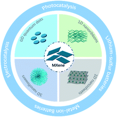
Two-dimensional (2D) materials, including graphene, transition metal dichalcogenides,1,2 hexagonal boron nitrides,3,4 black phosphorene5,6 and silene7,8 have shown promising applications in energy convention and storage (ECS). Transition metal carbides or nitrides, known as MXenes, are the new-generation 2D materials first prepared in 2011.9 Typically, MXenes are prepared by the selective removal of a layer from MAX precursors (in which, M represents early transition metal element, A represents the group IIIA, IVA, X represents C and/or N).9–11 Until now, over 30 kinds of MXenes have been synthesized from the corresponding MAX phase. They have many fascinating properties for ECS applications: (1) large planes for charge storage and 2D channels for ion transfer resemble other 2D materials, (2) excellent electrical conductivity owing to the metallic bone, whose bandgap can be tuned by surface functional groups,12 and (3) abundant functional groups on the surface (–F groups, –OH groups, –O groups), resulting in the hydrophilic surface and their superior performance in the ECS application.13,14In the past several years, many MXene derivatives with different structures, including 0D quantum dots, 1D nanoribbons, 2D nanosheets and 3D nanoflowers, have been successfully prepared. Their performance in ECS was also evaluated. However, the synthesis and application of these new MXene derivatives have never been comprehensively discussed. This review summarizes the recent progress in the synthesis of MXenes and their derivatives, as well as their performance in electrocatalysis, photocatalysis and rechargeable batteries (Scheme 1). Finally, the challenges and prospects of MXene derivatives in ECS are also proposed.
2 Synthesis of MXene
As shown in Fig. 1a, most MXenes are prepared from the MAX phase, where M and X atoms occupy the apex and center of the hexagonal crystal and A atoms interleave in MX layers. By taking advantage of this “laminar” structure, MX layers could be preserved after removing A atoms from MAX phases. However, the strong interaction between layers makes mechanical exfoliation difficult to generate 2D MXenes in contrast with other layered materials like graphene, where the weak van der Waals forces help maintain the structure.15 Therefore, many strategies have been developed to prepare MXenes. Current methods of preparing 2D MXenes and the differences between different routes are summarized in Table 1.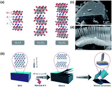 | ||
| Fig. 1 (a) Typical structure of MAX phases.12 This figure has been reproduced from ref. 12 with permission from American Chemical Society, copyright 2014. (b) Normal etching and delamination process of MXene.21 This figure has been reproduced from ref. 21 with permission from Elsevier, copyright 2019. (c, d) SEM graph for unreacted Ti3AlC2 particles (c) and HF-etched Ti3C2Tx (d).22 This figure has been reproduced from ref. 22 with permission from American Chemical Society, copyright 2012. | ||
| Synthesis methods | Applicable MXenes (published) | Advantages | Disadvantages |
|---|---|---|---|
| HF/in situ HF etching method | Suitable for most MXenes | Simple and generally suitable | Environmentally harmful and dangerous |
| Molten salt etching process | Especially suitable for the nitrides MXenes | Successfully etched the nitrides MXene | Hard to be completely etched |
| Alkali treatment | Ti3C2Tx | Environmentally friendly and more beneficial functional groups | Sensitive to the reaction conditions |
| Electrochemical etching | Ti3C2Tx | Mild and large-scale flakes | Easy to over-etching |
2.1 HF/in situ HF etching method
HF and in situ HF-etching are the main approaches to prepare MXene (Fig. 1b). Gogotsi and co-workers first reported the loosely stacked accordion-like MXene structure by selective etching of Al from bulk Ti3AlC2 in HF solution (50 wt%) (Fig. 1c and d).9 HF dissolved the Al layers by breaking Ti–Al bonds and released plenty of H2. Thereby, a violent bubbling phenomenon could be observed at the beginning of the reaction. At the same time, abundant functional groups including –F groups, –OH groups and –O groups were attached to Ti atoms on the surface, resulting in high hydrophilicity and unique electrochemical characters. Subsequently, Ti2CTx,16 V2CTx,17 Mo2CTx18 were successfully exfoliated by HF etching. It should be noted that the etching conditions depend on the structural properties of the MAX phase. For example, Nb2AlC required 90 h of etching time in 50 wt% HF, while Ti2CTx only needed treatment of 10 h in 40 wt% HF. The result was also confirmed by theoretical calculations. The calculation results verified the essential longer time and higher HF solution concentrations when etching Al from Nb2AlC than from Ti2AlC, for the bond energy of Nb–Al (1.21 eV) is a little bit higher than that of Ti–Al (0.98 eV).19 However, it's worth mentioning that too tough an etching procedure will result in more defects on the surface, which might potentially influence the properties of MXene sheets.20 The successful delamination of Al layers greatly weakens the interaction between layers, making it easy to exfoliate MXene layers from the adjacent ones.Considering the high risk and strong toxicity of HF, many efforts have been made to find milder and safer synthesis methods. In 2014, a few-layer MXene with larger interlayer spacing and fewer surface defects were achieved by using a mixture of LiF and HCl instead of HF solution.23 During the etching process, H+ and F− were released to form HF in situ. The intercalated metal ions and water molecules took place of Al atoms, promoting the expansion of the interlayered space and weakening the interlayered interaction. Importantly, this modified process enabled the size and quality of sheets regulatable by controlling the concentration of LiF and HCl.24 The combinations of other fluoride salts (such as KF, NaF, and CaF2) and acid (H2SO4) are also used to replace the original etchant. However, the use of these fluorinated salts cannot completely avoid the formation of HF, and –F groups also limit the application of MXene in electrochemical fields.9,25
Moreover, many organic molecules have been applied as the intercalation agent to generate a few-layer MXene from multi-layer MXene, such as dimethyl sulphoxide (DMSO), and tetramethylammonium hydroxide (TMAOH). On account of the presence of these intercalants, the loosely stacking multi-layer MXene can be delaminated into few-layer sheets, even a monolayer with followed ultrasound or shaking treatment.26,27
2.2 Molten salt etching process
HF and in situ HF etching are efficient ways of producing carbides MXene while behaving badly in the etching of the nitrides MXene. Two possible reasons were proposed to demonstrate the difficulty in producing the nitrides MXene. First, the calculation results showed the cohesive energy of Tin+1Nn was less than that of Tin+1Cn, which implied lower stability of Tin+1Nn. The formation energy of Tin+1Nn is also higher than that of Tin+1Cn, which indicated that Al atoms were strongly bonded in the Tin+1AlNn structure.28 To overcome such problems, Gogotsi and co-workers adopted a mixture of molten salt as the etchant to obtain nitrides MXene.29 In particular, Ti4AlN3 was first mixed with molten salt (59 wt% KF, 29 wt% LiF, 12 wt% NaF) in a 1![[thin space (1/6-em)]](https://www.rsc.org/images/entities/char_2009.gif) :
:![[thin space (1/6-em)]](https://www.rsc.org/images/entities/char_2009.gif) 1 mass ratio, and heated at 550 °C for 30 min under Ar atmosphere. Then, extra washing treatment with H2SO4 and DI water was required to dissolve the Al-containing fluorides. As confirmed from the XRD results, a strong broad (002) peak of Ti4N3Tx showed a shift from 7.6° to 6.3°, indicating the expanded interlayer distance. Also, no Al atom was observed according to EDX results, demonstrating the successful etching of nitrides MXene with molten salt.
1 mass ratio, and heated at 550 °C for 30 min under Ar atmosphere. Then, extra washing treatment with H2SO4 and DI water was required to dissolve the Al-containing fluorides. As confirmed from the XRD results, a strong broad (002) peak of Ti4N3Tx showed a shift from 7.6° to 6.3°, indicating the expanded interlayer distance. Also, no Al atom was observed according to EDX results, demonstrating the successful etching of nitrides MXene with molten salt.
2.3 Fluorine-free method
Recently, Li and co-workers reported a fluorine-free method to get the high-purity multilayer MXene via alkali hydrothermal treatment.30 High temperature and high NaOH concentration allow the complete dissolution of Al(oxide) hydroxides (Fig. 2a and b), and further delamination with TMAOH or DMSO and ultrasound treatment can help produce a few-layer MXene with smaller sizes.31 Different from fluorine-assisted methods, more O-containing groups are distributed on the surface instead of –F groups, which may be beneficial for the electrochemical performance. Although alkali treatment avoids the generation of HF, tough conditions may destroy the internal structure and create more defects on the surface.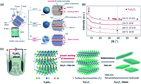 | ||
| Fig. 2 (a) The reaction of Ti3AlC2 with NaOH aqueous solution under different conditions. (b) XRD results of MXene treated in different temperatures and alkali concentrations.30 This figure has been reproduced from ref. 30 with permission from Wiley-VCH, copyright 2018. (c) The configuration of electrochemical cell and schematic diagram of the electrochemical etching of Ti3C2Tx with the combination of NH4Cl and TMAOH.32 This figure has been reproduced from ref. 32 with permission from Wiley-VCH, copyright 2018. | ||
Beyond this traditional wet chemical etching, electrochemical etching is an alternative way of preparing MXene sheets. Yang and co-workers developed an electrochemical etching method in a mixture of NH4Cl and TMAOH organic systems.32 Two pieces of bulk were used as the working electrode and counter electrode, while only the working electrode underwent the etching process (Fig. 2c).
With a constant applied potential (5 V), chloride ions worked as the Ti–Al bonds breaker and the generated NH4OH helped expand the edge. The exfoliated sheets were mostly single or double layers with an average lateral size of over 2 μm, larger than the traditional HF-etched MXene. In addition, Ti3C2Tx sheets achieved by electrochemical etching generally show a similar stacked morphology as bulk Ti3AlC2 without an obvious expansion because the reaction process does not involve violent gas release. It should be noted that the selection of electrolytes also plays a crucial role in the result of etched MXene. For example, electrochemical treatment in NaCl, HCl solutions always generates amorphous carbon, blocking further etching process.33 Sun and co-workers found that a three-layer structure composite was generated when dealing MAX with 2 M HCl aqueous electrolyte.34 This hybrid consisted of carbon-derived carbides (CDCs), unetched MAX and MXene, which needed further purification to harvest pure MXene sheets.
Above all, by utilizing the intensity difference between M–A bonds and M–X bonds, MXene could be obtained from bulk MAX phases through specific etching methods, such as HF acid etching, molten salts etching and other fluorine-free routes. It should be noted that the etching conditions varied widely with the M–A bond energies.19 The higher the M–A bond energies, the longer etching time and higher etchant concentration are required. Furthermore, MAX particles' size plays an important role in the etching rate and reaction conditions.17 Pre-treating the MAX powder by attrition milling could greatly reduce the etching time without enhancing overall yield.
2.4 Other bottom-up method
Except for the etching method mentioned above, other bottom-up methods, such as chemical vapor deposition,35,36 template method,37,38 plasma-enhanced pulsed laser deposition (PEPLD),39 have been created to fabricate ultrathin 2D MXene with good crystallinity, especially for Mo2C materials. Gogotsi and co-workers synthesized α-Mo2C crystals on the molybdenum–copper foil under the CH4 atmosphere, where the Mo atoms react with C atoms from CH4 at the melt surface.35 The obtained Mo2C exhibited an ordered crystal structure of tungsten carbide crystal according to the HRTEM image. These methods could better tune the size and thickness of 2D MXene crystals, enriching synthesis approaches to 2D MXene sheets.3 Synthesis of Ti3C2Tx MXene derivatives
MXenes have shown great potential in ECS because of the 2D lamellar structure, high conductivity and abundant functional groups on the surface. Recently, the design of MXene derivatives with different morphologies and properties has drawn increasing attention, which shows improved performance in ECS compared to pristine MXene. The morphology engineering could be realized by choosing different synthesis methods. In this section, we summarize the synthesis methods of typical Ti3C2Tx MXene derivatives, including 0D quantum dots (0D QDs), 1D nanoribbons (1D NRs), 2D nanosheets (2D NSs), and 3D nanoflowers (3D NFs). Specific synthetic routes to Ti3C2Tx MXene derivatives of different morphologies and their further application are listed in Table 2.| Sample | Structure | Synthetic method | Application | Ref. |
|---|---|---|---|---|
| Ti3C2 QD | 0D QDs | Hydrothermal | Multicolor cellular imaging | 40 |
| Ti3C2 QD | 0D QDs | Hydrothermal | Li–S battery | 41 |
| Ti3C2 QD/g-C3N4 | 0D QDs | Hydrothermal | Photocatalytic hydrogen production | 42 |
| Ti3C2 QD | 0D QDs | Solvothermal | — | 43 |
| N-Ti3C2 QD | 0D QDs | DETA-assisted solvothermal | Selective Cu2+ detection | 44 |
| Ti3C2 QD | 0D QDs | Ultrasound | Fe3+ detection | 45 |
| Ti3C2 QD | 0D QDs | Reflux | — | 46 |
| Ti3C2 NR | 1D NRs | Alkali treatment of MXene | Na/K-ion battery | 47 |
| Ti3C2 NR | 1D NRs | Alkali treatment of MXene | Li–S battery | 48 |
| Na0.23TiO2/Ti3C2 | 1D NRs | Partial alkali treatment | Li/Na-ion battery | 49 |
| Ti3C2 NR/Ti3C2 | 1D NRs | Partial alkali treatment | Humidity sensor | 50 |
| h-Ti3C2/CNTs | 1D NRs | Alkali treatment of MXene | Na–O2 batteries | 137 |
| Ti3C2 NR | 1D NRs | Alkali treatment of MAX followed by HF etching | HER | 51 |
| TiO2/Ti3C2 | 2D NSs | Hydrothermal | Hexavalent chromium removal | 52 |
| TiO2/C | 2D NSs | Hydrothermal and annealing | Photocatalytic water splitting | 53 |
| Ti3C2/TiO2/PANI | 2D NSs | Hydrothermal | Electromagnetic wave absorption | 134 |
| PANI@TiO2/Ti3C2Tx | 2D NSs | Hydrothermal | Supercapacitors | 138 |
| TiO2/Ti3C2 | 2D NSs | Solvothermal | 54 | |
| TiO2/C | 2D NSs | Calcination in CO2 atmosphere | Photocatalytic water splitting | 53 |
| N-TiO2/C | 2D NSs | Calcination of modified MXene in CO2 atmosphere | Photodegradation | 55 |
| TiN/C | 2D NSs | Calcination in N2 atmosphere | Supercapacitor | 56 |
| NTO/KTO | 3D NFs | Hydrothermal in alkali solution | Na/K-ion battery | 57 |
| Ti3C2–TiO2 | 3D NFs | Alkali treatment followed by ion change and heating | Photocatalytic water splitting | 58 |
| TiO2–Ti3C2– | 3D NFs | Hydrothermal in alkali solution | Photocatalytic water splitting | 133 |
| Na2Ti3O7@C | 3D NFs | Hydrothermal in alkali solution | Na-ion battery | 135 |
| HNTO/CS | 3D NFs | Hydrothermal in alkali solution | K-ion battery | 136 |
| TiO2/C | 3D NFs | Alcohol-thermal decomposition | Dehydrogenation of sodium alanates | 59 |
3.1 Synthesis of 0D quantum dots
The 0D quantum dots are a kind of common 2D material derivatives with size advantage and unique optical properties originating from the quantum confinement and edge effects. In the past decades, quantum dots derived from different 2D materials, such as graphene and MoS2, are successfully produced.60,61 The MXene quantum dots (MQDs) were first prepared by Xue and co-workers in 2017.40 The as-prepared MQDs showed the same hexagonal lattices as the MAX phase, while exhibited smaller diameters of less than 10 nm.62Generally, 0D MQDs are exfoliated from selected precursors via chemical or physical methods, such as hydrothermal/solvothermal,63,64 ultrasound treatment65,66 and reflux.46 Defects are created in this process and are served as the cutting points so that the layer sheets could be cut into smaller QDs. Up to now, the hydrothermal method has been considered the most common way of preparing MQDs. The resulting MQDs exhibit good solubility in water and ethanol. Xue and co-workers synthesized the monolayer MQDs with the quantum yields of 10% using the hydrothermal method (Fig. 3a).40 The average lateral particle sizes were tuned from 2.9 nm to 6.2 nm when the temperature rose from 100 to 150 °C. To be noted, the crystal structure also changed with the reaction temperature. In particular, MQDs treated at 100 °C showed the same structure of MXene, as confirmed by the lattice spacing (0.266 nm) assigned to the (0110) facet of MXene. When the temperature got higher, the (101) facet of TiO2 could be observed at 120 °C, and higher temperature (150 °C) led to the violent etching of Ti atoms and the undesirable formation of amorphous carbon dots (Fig. 3b).
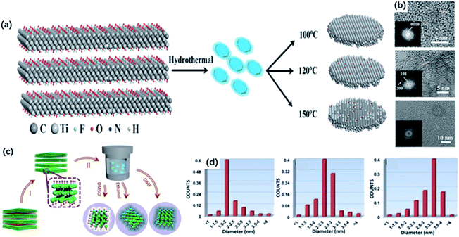 | ||
| Fig. 3 (a) Scheme for the synthesis of Ti3C2 QDs by a hydrothermal method at different temperatures. (b) HRTEM graphs of MQDs treated in 100 °C, 120 °C, 150 °C, respectively.40 These figures have been reproduced from ref. 40 with permission from Wiley-VCH, copyright 2017. (c) Schematic diagram of the preparation of MQDs via solvothermal treatment in different solvents, including DMF, DMSO and ethanol. (d) Size distributions of DMF-treated, DMSO-treated, ethanol-treated MQDs.43 This figure has been reproduced from ref. 43 with permission from Wiley-VCH, copyright 2018. | ||
Except for the hydrothermal process, solvothermal is another effective way to prepare MQDs by changing the reaction medium, which determines the sizes and quantum yields of MQDs. Xu and co-workers studied the relevance between solvents and properties of MQD via the solvothermal treatment of MXene.43 As shown in Fig. 3c, MQDs were prepared at 120 °C for 6 h in ethanol, dimethylformamide (DMF) and dimethyl sulfoxide (DMSO). As a result, MQDs treated in DMF possessed the largest average diameters of 3.3 ± 0.2 nm and the highest quantum yields of 10.7% among them, whereas the quantum yields of MQDs treated with ethanol and DMSO are only 6.9% and 4.1%, respectively (Fig. 3d). It was suggested that the physical properties of solvents, such as combined action of polarity, oxidation and boiling points could exert influences on the sizes and optical properties of MQDs. Specifically, high solvent polarity led to a strong interaction between solvent molecules and MXene sheets, and the low boiling point of the solvent caused higher pressure during the reaction. Under such experimental conditions, both resulted in smaller sizes and higher yields of MQDs. In addition, heteroatom doping during the hydrothermal/solvothermal treatment could significantly improve the electronic properties of QDs, induce more active sites on the surface, as well as obtain higher yields.67–69
Feng and co-workers designed a DETA-assisted solvothermal route to obtain in situ nitrogen-doped MQDs in DMF solution.44 N-MQDs showed smaller particle sizes than MQDs because of the contribution of N to the increased surface defects. The N-MQDs exhibited improved fluorescence emission traits, which probably resulted from the strong electron-donation effect. Xu and co-workers developed N-MQDs through a hydrothermal process using ethylenediamine as a nitrogen source, which showed the highest quantum yields (18.7%) among the past reports.69 The effect of N-doping on quantum yields was further verified by DFT calculations, where O-terminated Ti3C2 was used. In terms of the calculation results, a prominent gap state and wide energy gap could interpret the increased lifetime of carriers and improved quantum yields (Fig. 4a). Also, nitrogen doping introduced gap states close to the LUMO, that is, nitrogen doping of MQDs could accelerate the electron migration and eventually increase the carrier lifetime. Sometimes, nitrogen-containing solvents can serve as the nitrogen source without the additional agent as well. Lu and co-workers prepared highly fluorescent N-MQDs using dimethylformamide (DMF) as both, the solvent agent, and doping addictive, showing a significantly higher quantum yield of 11.13% than with ethanol (1.09%) and water (0.34%) system.67
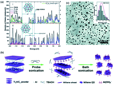 | ||
| Fig. 4 (a) Total and projected density of states by DFT calculation of (I) N-doped Ti3C2 QDs and (II) Ti3C2 QDs.69 This figure has been reproduced from ref. 69 with permission from Royal Society of Chemistry, copyright 2018. (b) Schematic diagram of the preparation of MXene QDs via sonication treatment. (c) TEM graph of the sonication treated MXene QDs. Inset (top-right) in (c): lateral sizes of MXene QDs by statistical analysis.66 This figure has been reproduced from ref. 66 with permission from Royal Society of Chemistry, copyright 2017. | ||
Moreover, ultrasound treatment could be introduced to prepare MQDs, breaking MXene into small pieces and exposing more edges and sites.70,71 Zhang and co-workers designed a facile one-step ultrasound method, where delaminated MXene were sonicated for 10 h to obtain MQDs (Fig. 4b).45 The resulting MQDs exhibited spherical-like morphology and displayed monodisperse uniform distribution (Fig. 4c). Yu and co-workers combined TMAOH-assisted exfoliation and mechanical treatment to produce MQDs from pristine bulk Ti3AlC2 instead of using fluorine solvents.66 Pre-sonication of Ti3AlC2 was applied to expose more fresh edges and surfaces for the TBAOH etching process.
It is worth mentioning that the size of MQDs primarily depends on the temperature and reaction medium. Tuning the reaction conditions is important for achieving different sizes and higher yields of MQDs. The average lateral particle sizes become larger when the temperature rises, while the too high temperature may lead to the undesirable change of crystal structure. The solvent medium with a low boiling point also contributes to smaller sizes of MQDs because of the larger pressure during the reaction. In addition, heteroatom doping during reaction could decrease the average sizes of MQDs and achieve higher quantum yields, thanks to the prominent gap state and wide energy gap. More efforts could be made to design the expected structure by optimizing the reaction conditions.
3.2 Synthesis of 1D nanoribbons
One-dimensional nanomaterials, such as carbon nanotubes, are widely used in energy storage and wearable device applications owing to their high specific surface area, abundant exposed active sites and great mechanical reliability.72–75 Inspired by the special properties, nanoribbons derived from 2D materials like graphene were successfully synthesized by breaking the chemical bonds.76MXene nanoribbons (MNRs) were first fabricated by continuous shaking treatment of HF-etched Ti3C2 in aqueous 6 M KOH solution for 72 h at room temperature (Fig. 5a).77 Few MNRs appeared at the first hour, and longer MNRs were generated with the longer treatment time. The obtained MNRs displayed a narrow width of 6–22 nm. As confirmed from the XPS spectrum, the signal of F1s was almost unobservable after alkalization and a distinguishable signal of the Ti–O group appeared, indicating the transformation of –F groups to –OH groups. Also, the XRD pattern showed that the (002) peak of Ti3C2 was shifted to 7.1° from 8.9°, suggesting the expansion of interlayer spacing resulting from the intercalation of K+ into layers (Fig. 5b). Given little research has been done on MNRs, Lian and co-workers proposed a possible forming mechanism of MNRs. Initially, alkali treatment promoted the transformation of the surface group from –F to –OH, which strengthen the rapid adsorption and the intercalation of K+ into layers. Afterward, the mechanical shaking treatment enhanced the diffusion of OH− and K+ along the channels of interlamination contributing to the O-terminated MNRs, and thus, splitting MNRs from the delaminated sheets. Li and co-workers treated MXene with different concentrations of KOH solutions (6, 12 and 24 mol L−1) for 2, 10 and 20 h to determine the key impacts on the morphology and quantity of MNRs, including the concentration of KOH solutions and the reaction time.50 As a result, it was demonstrated that the diameter and quantity of nanowires were proportional to the KOH concentration, while overlong reaction time might result in the agglomeration of nanoribbons. Yuan and co-workers developed a new strategy to fabricate MNRs directly from the MAX phase via the KOH-assisted treatment (Fig. 5c).51 Ti3AlC2 powders were first added to 6 M KOH and stirred for 96 h at room temperature, and MNRs with the width of 50 nm were harvested without being destroyed or collapsed after the HF-etching treatment (Fig. 5d). In the process, OH– served as a “scissor” to destroy Ti–C bonds in Ti3AlC2, fabricating the crack propagating to the edge. Interestingly, the pre-treatment with alkali solution can shorten ion transfer path and increase surface area, making the follow-up etching more efficient. Inspired by this study, a one-step alkalization treatment was developed to generate MNRs from Ti3AlC2 without using a fluorine-containing etchant.78 Sugarcane-like transitional etching products were formed by the hydrothermal treatment after grounding a different ratio of MAX and KOH powders with pretty small amounts of water added. With the increase of KOH content and longer reaction time, MNRs with narrow width were finally obtained.
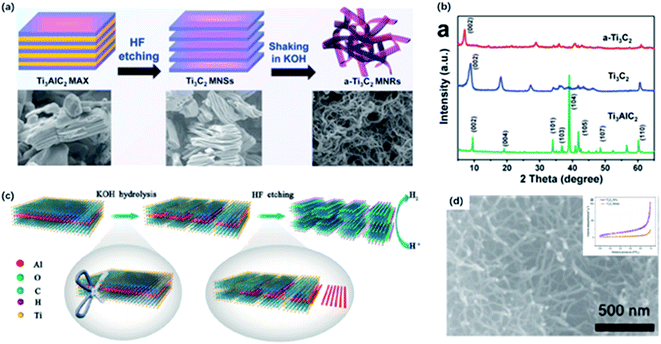 | ||
| Fig. 5 (a) Schematic of preparation of Ti3C2 MNRs. (b) XRD patterns of Ti3C2 MNRs, Ti3C2 and Ti3AlC2.47 This figure has been reproduced from ref. 47 with permission from Elsevier, copyright 2017. (c) Schematic showing the synthesis of Ti3C2 NF directly from Ti3AlC2 via KOH-assisted treatment. (d) High magnification SEM image of Ti3C2 NFs. Inset (top-right) in (d): N2 adsorption–desorption isotherm of Ti3C2 NFs and Ti3C2 flakes.51 This figure has been reproduced from ref. 51 with permission from American Chemical Society, copyright 2017. | ||
3.3 Synthesis of 2D nanosheets
Ti3C2Tx sheets are promising candidates for ECS due to their specific surface area and high conductivity in a 2D planar structure. Whereas the oxidation stability of Ti3C2Tx is unsatisfactory due to the exposure of the large portion of Ti atoms on the surface.79 After exposing in the open air at room temperature, anatase TiO2 nanoparticles might form at the edge sites only in a week according to fast Fourier transform (FFT).80 However, the rich titanium atoms could also act as nucleating sites managing the in situ growth of TiO2 on Ti3C2 layers during oxidation in the meanwhile. Importantly, the unique properties of TiO2 and the interface between different components in the heterostructure improve the performance in ECS, particularly in photocatalysis compared to a single component. According to previous reports, hybrid nanosheet structure has been fabricated by partial or complete oxidation of MXene.53,81,82The oxidation degree of the obtained MXene hybrid depends on the condition of the synthesis method. The controlled oxidation of Ti3C2Tx MXene could be a promising method to prepare functional TiO2/MXene hybrids. It is reported that hydrothermal treatment is a common way to get partially oxidized MXene under relatively low temperatures.83,84 Zhang and co-workers constructed the hierarchical accordion-like TiO2/Ti3C2 hybrid via a facial hydrothermal strategy.85 TiO2 nanoparticles were uniformly covered on the MXene sheets, contributing to an expanded interlayer space. Importantly, the reaction solvent also determines the nanoparticle size of TiO2.86,87 As we know, the particle size influences the photocatalytic activity of TiO2.132 It has been reported that reducing the size of TiO2 particles could decrease the path of holes during the photocatalytic process, contributing to the increased photocatalytic efficiency. In addition, the smaller particles possessed a larger specific surface area, increasing the contact area of TiO2 and MXene.54 Zhang and co-workers figured out the existence of a moderate amount of ethanol under the hydrothermal condition could effectively reduce the size of TiO2 nanoparticles.54 Ethanol weakened the contact between the TiO2 nucleus and water because of the relatively high viscidity and molecular weight, leading to the formation of smaller-sized TiO2. In addition, hybrids increase the interlayer distance and improve the electrochemical properties.88 Moreover, it has been demonstrated that the exposed facet of TiO2 could be controlled by adding a morphology-directing agent.89 In order to design the favorable growth of TiO2, Peng and co-workers developed a new strategy of synthesizing the TiO2/Ti3C2 heterojunction nanocomposites in 1.0 M HCl solution via the hydrothermal treatment of Ti3C2 (Fig. 6a).90 With the addition of 0.1 M NaBF4, which served as the morphology-directing reagent, the exposing (001) facets of anatase TiO2 could be selectively controlled without any additional Ti sources (Fig. 6c). This modification method has been widely utilized to manage the favorable growth of TiO2 with specific exposing facets on Ti3C2 sheets.84,91,92 The in situ generated TiO2 nanoparticles also exhibited an aggregation distribution on the surface and interlayers, which contributed to the sandwich structure (Fig. 6b).52,93 Along with the increased reaction time, the size of nanoparticles gradually increased as well.52
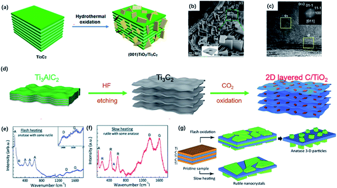 | ||
| Fig. 6 (a) Schematic of the preparation of (001) TiO2/Ti3C2 composite by hydrothermal treatment. (b) SEM photos of (001) TiO2/Ti3C2 composite. (c) TEM image of (001) TiO2/Ti3C2. Inset (top-right) in (c): the indexed FFT image of TiO2 showed the exposing (001) facets.90 This figure has been reproduced from ref. 90 with permission from American Chemical Society, copyright 2016. (d) Scheme diagram of the preparation of 2D-layered C/TiO2 hybrids via CO2 calcination.82 This figure has been reproduced from ref. 82 with permission from Wiley-VCH, copyright 2017. (e, f) Raman spectra of the final product of flash heating and slow heating.97 (g) Schematic diagram of two oxidation regimes including flash oxidation and slow heating. This figure has been reproduced from ref. 97 with permission from Royal Society of Chemistry, copyright 2014. | ||
Except for the hydrothermal process, calcination could be an alternative way of producing oxidized MXene. It has been shown that the heat treatment of Ti3C2Tx in the air or flowing CO2 atmosphere could result in complete oxidation of TiO2 embedded in the amorphous carbon layer by controlling the appropriate temperature.94,95 In the early time, Naguib and co-workers first studied the fast flash oxidation from Ti3C2Tx to TiO2@C composites at 1150 °C for 30 seconds under air atmosphere.96 However, it seemed hard to control the reaction during the violent oxidation process. Gogotsi and co-workers explored two oxidation regimes including flash oxidation and slow heating process to confirm a different mechanism of oxidation (Fig. 6d).97 During flash oxidation, the Ti atoms on the surface were first oxidized into planar anatase thin film (Fig. 6e). With more innermost Ti atoms migrating to the surface, vertical nanoparticles were generated on the nanosheets. By contrast, the slow heating process only led to the formation of the thin rutile TiO2 sheet on the surface (Fig. 6f). Moreover, Yuan and co-workers reported 2D layered TiO2/C hybrid via one-step CO2 oxidation of Ti3C2 for 1 h. The CO2 molecules break Ti–C bonds to form Ti–O bonds (Fig. 6g).82 The reaction process can be expressed as followed:
| Ti3C2 + 3CO2 → 3TiO2 + 5C |
The generated TiO2 sheets were anchored on carbon layers, forming the well-preserved 2D-layered architecture. It is worth mentioning that the heating temperature had a great impact on the structure of TiO2/C composites. When the heating temperature reached 800 °C, TiO2 tended to form particles with lower surface energy instead of sheets, and carbon layers would get thinner because of the oxidation. When the temperature got higher, carbon was completely oxidized so that no carbon layers could be observed under 900 °C calcination.
Moreover, calcination under different atmospheres could also contribute to the formation of different titanium compounds. Guo and co-workers fabricated a 2D-layered C@TiN after one-step nitridation at 750 °C under NH3 conditions.56 NH3 molecules first formed Ti–N bonds by breaking Ti–C bonds, and H atoms provided by NH3 reacted with C atoms to generate CH4 molecules, which were decomposed into C and H atoms again. These C atoms were deposited on the surface of TiN sheets, contributing to a hybrid C@TiN structure. Huang and co-workers synthesized TiS2@NSC nanosheets by annealing under H2S/Ar atmosphere from PDA-covered Ti3C2Tx precursor, which shed light on the design of effective cathode materials for lithium–sulfur batteries.98
3.4 Synthesis of 3D nanoflowers
As mentioned above, MNRs could assemble into a 3D porous framework by stirring in an alkali solution at room temperature, which greatly shortened the ionic diffusion length. Dong and co-workers designed a continuous oxidation and alkalization process to generate MXene nanoflowers via hydrothermal treatment in 1 M KOH and NaOH solution with the addition of the small amount of 30 wt% H2O2 (Fig. 7a).57 Compared with MNRs formed in KOH solution, the typical diffraction peak of Ti3C2 in the XRD pattern completely disappeared. New peaks at 24.3° and 48° corresponding to new species NaTi1.5O8.3 and K2Ti4O9 were observed (Fig. 7b). In addition, the almost unchanged interlayered space eliminated the possibility of intercalation. The XRD results illustrated that TiO2 was oxidized at the early stage, and then the alkalization environment under hydrothermal conditions promoted the formation of sodium or potassium titanates. The as-prepared long curved MNRs were formed and assembled into the urchin-like structure. Up to now, there are many works based on 3D nanoflower structure by hydrothermal treatment of MXene in alkali solution.99,100 The unique 3D structure and properties promote the further application in ECS. Furthermore, alkali metal ions could be replaced by H+ after immersing in the acid solution for a while and further calcination could generate TiO2 nanoflowers. Li and co-workers reported the successful transformation from Ti3C2 to Ti3C2/TiO2 nanoflowers with improved photocatalysis performance (Fig. 7c).58 Ti3C2/TiO2 hybrids were produced after the ion change process in 0.1 M HCl solution and followed by annealing at different temperatures. As the heating temperature increased, the content of anatase TiO2 became higher, and the “petals” gradually became wider and shorter according to SEM images (Fig. 7e and f).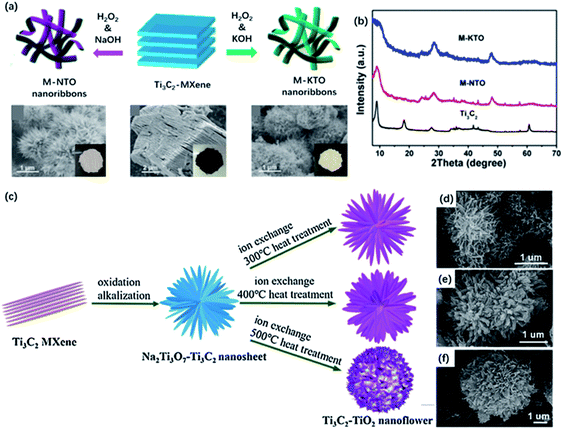 | ||
| Fig. 7 (a) Schematic illustration of the fabrication of M-NTO or M-KTO nanoribbons obtained by hydrothermal treatment in NaOH and KOH, respectively. (b) XRD pattern Ti3C2, M-NTO and M-KTO.57 This figure has been reproduced from ref. 57 with permission from American Chemical Society, copyright 2017. (c) Schematic of the preparation of Ti3C2/TiO2 nanoflowers with different heating temperatures. (d–f) SEM pictures of Ti3C2/TiO2 nanoflowers at different temperatures: (d) 300 °C, 400 °C, 500 °C.58 This figure has been reproduced from ref. 58 with permission from Elsevier, copyright 2018. | ||
Moreover, by controlling the conditions of hydrothermal, the completely oxidized nanoflowers could be obtained instead of 2D nanosheets. Zou and co-workers developed a hierarchical nanoflower-shaped TiO2/C composite, achieved by alcohol-thermal decomposition of MXene in a mixing solution of EG, HF solution, and IPA.59 It's noteworthy to mention that the modification of solvents to alert the F-containing condition may feasibly control the growth of the lattice plane.101,102 The –F groups on the surface make it possible to vary orientational TiO2/C hybrids by tuning the growth of crystallographic planes.
4 Application
Owing to the controllable morphology and unique properties compared with pristine MXene, MXene derivatives have attracted extensive attention, especially in ECS. In the following section, we outline recent progress based on MXene derivatives with enhanced performance in ECS, mainly including photocatalytic/electrocatalytic hydrogen production, metal ion batteries and lithium–sulfur batteries.4.1 Photocatalytic hydrogen production
The generation of H2 from water by photocatalysis is a clean method to convert solar energy into hydrogen fuel. Up to now, a variety of photocatalysts have been developed for the utilization of light-driven hydrogen evolution, such as metal oxides, nitrides, sulfides.103–106However, the single component suffered from the fast photoexcited carrier recombination, resulting in poor H2 production properties. In this case, co-catalysts are needed to help capture carriers and prevent the recombination of electrons and holes. Noble metals are the most ideal co-catalysts to promote photogenerated electron transfer and the separation of electrons and holes, but their extremely high price limit their actual applications in photocatalysis. In recent years, MXenes have aroused noteworthy attention in photocatalysis as co-catalysts owing to the excellent electrical conductivity, hydrophilicity, and low Fermi level compared to semiconductors. It has been demonstrated from DFT calculations that the O-terminated Ti3C2 exhibited near-zero Gibbs free energy for hydrogen adsorption (ΔGH) and the most positive value of EF, implying high H2 evolution activity and ability to capture the photo-induced electrons.107
![[thin space (1/6-em)]](https://www.rsc.org/images/entities/char_2009.gif) 342 μmol g−1 h−1, which was 136 times higher than that of pure CdS. The superior photocatalytic activity resulted from the strong combination of two components to facilitate the carrier transfer. Similarly, Li and co-workers designed Ti3C2 QDs@g-C3N4 nanosheets via a self-assembly method. The as-obtained Ti3C2 QDs were intimately immobilized on g-C3N4 nanosheets as confirmed from TEM images (Fig. 8a).42 With the loading of Ti3C2 QDs, the pore-size distribution is relatively dispersed, which would significantly facilitate the charge transfer process. Also, an increased lifetime of charge carriers could be observed on account of the properties of capturing electrons supported by the metallic conductivity of Ti3C2 QDs. As a result, g-C3N4@Ti3C2 QD composite (5.5 wt% Ti3C2 QDs loaded) showed a greatly-enhanced photocatalytic H2 generation activity (5111.8 μmol g−1 h−1) (Fig. 8b).
342 μmol g−1 h−1, which was 136 times higher than that of pure CdS. The superior photocatalytic activity resulted from the strong combination of two components to facilitate the carrier transfer. Similarly, Li and co-workers designed Ti3C2 QDs@g-C3N4 nanosheets via a self-assembly method. The as-obtained Ti3C2 QDs were intimately immobilized on g-C3N4 nanosheets as confirmed from TEM images (Fig. 8a).42 With the loading of Ti3C2 QDs, the pore-size distribution is relatively dispersed, which would significantly facilitate the charge transfer process. Also, an increased lifetime of charge carriers could be observed on account of the properties of capturing electrons supported by the metallic conductivity of Ti3C2 QDs. As a result, g-C3N4@Ti3C2 QD composite (5.5 wt% Ti3C2 QDs loaded) showed a greatly-enhanced photocatalytic H2 generation activity (5111.8 μmol g−1 h−1) (Fig. 8b).
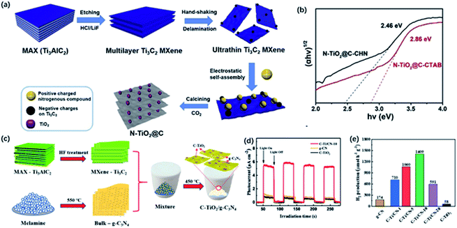 | ||
| Fig. 9 (a) Schematic of the fabrication of the preparation of 2D layered N-TiO2@C. (b) The bandgap energy of N-TiO2@C.55 This figure has been reproduced from ref. 55 with permission from Elsevier, copyright 2019. (c) Schematic illustration of the preparation of C-TiO2/g-C3N4 hybrid. (d) Intermittent transient photocurrent response spectra of C-TiO2/g-C3N4 hybrid. (e) Photocatalytic H2 production rate of C-TiO2/g-C3N4 hybrid.108 This figure has been reproduced from ref. 108 with permission from Elsevier, copyright 2020. | ||
The as-prepared TiO2/C could serve as the co-catalysts assisting the transfer of carriers as well. Moreover, g-C3N4 with layered structure has been proved to be a hopeful candidate for photocatalysis, while co-catalysts are still needed to capture carriers and offer enough active sites to improve overall photocatalysis performance. Han and co-workers prepared C-TiO2/g-C3N4 composite via a typical calcining process of pre-synthesized bulk g-C3N4 from melamine and etched Ti3C2Tx at 450 °C for 5 h (Fig. 9c).108 After calcination, Ti3C2 was completely converted to anatase phase, meanwhile, bulk g-C3N4 was changed to g-C3N4 sheets, which may enhance the photocatalytic activity of H2 generation. C-TiO2/g-C3N4-10 (the ratio of Ti3C2 to g-C3N4 is 10) exhibited the highest photocatalytic H2 generation rate of 1409 μmol g−1 h−1, which was about 8 and 24 times higher than g-C3N4 and C-TiO2, respectively (Fig. 9e). Note that the marked hydrogen production activity resulted from the intimate heterojunction between C-TiO2 derived from MXene and g-C3N4, which efficiently facilitate the transfer of photocatalytic carriers and inhibit the recombination of electrons and holes.
Compared to 2D sheets, MQDs show excellent solvent solubility and electronic properties, which are beneficial to photocatalytic activity. On the other hand, TiO2 derived from Ti3C2Tx is the most widely investigated photocatalyst. The intimate interfacial contact between TiO2 nanoparticles and 2D sheets could facilitate the separation of photo-induced carriers and optimize photocatalytic activity. More efforts can be made to develop the modification methods of synthesis to better control the beneficial morphology and new hybrids of MXene and MXene derivatives to promote photocatalytic activity.
4.2 Electrocatalytic hydrogen evolution reaction
Except for the utilization of solar energy, the conversion of electrical energy to chemical energy like electrocatalytic hydrogen evolution reaction (HER) could be an efficient way of producing H2. To date, noble metals and their oxides are considered the most efficient electrocatalysts. However, high cost and scarcity limit their practical applications. In recent years, many noble metal-free catalysts have been developed with high activity in HER, while their poor charge transfer characteristics and limited exposing edges remain problems. MXene with high metallic electrical conductivity and the large surface area attracted huge attention. It has been demonstrated that O-containing groups on the surface are the catalytic active sites that are in favour of the fast charge transfer.111 Besides, MXene derivatives with unique morphology have shown enhanced performance in electrocatalytic HER.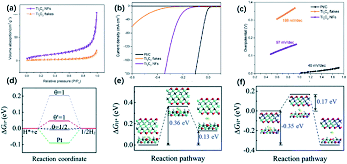 | ||
| Fig. 10 (a) N2 absorption–desorption image of Ti3C2 NFs and Ti3C2 nanosheets. (b) HER properties of Ti3C2 NFs: LSV (b) and Tafel slopes (c) of Ti3C2 NFs, Ti3C2 nanosheets, and Pt/C electrodes.51 This figure has been reproduced from ref. 51 with permission from American Chemical Society, copyright 2018. (d) ΔGH value for hydrogen evolution at zero potential (pH = 0) on the edges of Ti3C2 (blue lines) and MXene nanoribbons (red line) at different H* coverage. (e, f) ΔGH value of the Tafel reaction for H2 formation on the edges of (e) Ti3C2 and (f) MXene nanoribbons.116 This figure has been reproduced from ref. 116 with permission from Royal Society of Chemistry, copyright 2018. | ||
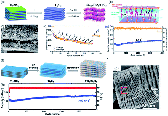 | ||
| Fig. 11 (a) Schematic of the preparation of the sandwich-like Na0.23TiO2/Ti3C2 composite via alkali treatment. (b) Energy-storage mechanism in Na0.23TiO2/Ti3C2 composite. (c) SEM picture of Na0.23TiO2/Ti3C2 composite. (d, e) Rate performance (d) and long-term cycling performance at 5 A g−1 (e) of Na0.23TiO2/Ti3C2 composite.49 This figure has been reproduced from ref. 49 with permission from Elsevier, copyright 2018. (f) Schematic diagram of synthesis of the partial-oxidized TiO2/Ti3C2 nanohybrid. (g) FESEM picture of accordion-like TiO2/Ti3C2 nanohybrid. Inset in (g): FESEM of the red zone circled (h) cycling performance of TiO2/Ti3C2 nanohybrid at a 2000 mA g−1 (high rate).117 This figure has been reproduced from ref. 117 with permission from Elsevier, copyright 2018. | ||
Compared to the MXene sheets, 1D NRs show more exposing active sites and increased surface area, which are beneficial to the HER. In the future, more hybrids of 1D NRs and other electrocatalysts can be produced to shorten the diffusion pathway and promote the charge transfer process.
4.3 Metal-ion batteries
In recent years, developing new generation energy storage devices has attracted tremendous attention due to the increasing demand for high energy density and harmless environmental impact. Until now, rechargeable batteries are the most widely used energy storage device, in which the performance mainly depends on the properties of electrode materials. Hence, the development of electrode materials is vital to improving electrochemical performance. Metal-ion batteries featuring high energy capacity, lightweight and long cycle life are the first commercial devices. Since the latest lithium-ion battery was produced in 1991, the development of lithium-ion batteries has attached great importance to the utilization of portable electronic equipment and electric vehicles. MXene showed considerable potential in constructing high-performance electrode material for lithium-ion batteries due to the high conductivity and abundant active sites. As the most studied MXene, Ti3C2 has a theoretical capacity of ∼320 mA h g−1, while it only showed a capacity of ∼120 mA h g−1 in the experiments, owing to the influence of the surface termination groups. But high capacities are found in O-terminated MXene, attributed to the formation of bilayer Li atoms between the layers. As confirmed from DFT calculations, Li diffusion barriers are pretty low, resulting in the high rate performance.121 Therefore, many strategies, such as oxidation and alkalization, have been developed to optimize the storage of Li-ions.87,88,991D NRs derived from MXene have been comprehensively discussed as the promising electrode of metal-ion batteries these years. However, poor electron conductivity and slow ion transfer limit the capacitance and cycling performance. Future experiments can focus on the combination of MXene derivatives and other energy storage materials with high conductivity to improve the performance of the electrode system.
4.4 Lithium–sulfur batteries
Lithium–sulfur batteries have been considered as the promising candidate for next-generation batteries owing to the high theoretical capacity and rich reserves of sulfur. Nevertheless, further practical application is restricted by the poor conductivity of sulfur, huge volume change during cycling, and “shuttle effect” caused by the soluble lithium polysulfides (LiPSs) intermediates with a negative impact on the capacity and cycling performance.125 To address these issues, intensive efforts have been made, such as employing conductive carbon-based materials in the system. However, carbon-based materials exhibited poor LiPSs adsorption, especially for high sulfur loading batteries.126 In this case, some polar materials, such as transition metal oxides, sulfides, have been inducted as additives. These polar materials exhibited high trapping ability and efficient catalytic effects on the conversion of LiPSs, contributing to the enhanced capacity and cycling performance. Recently, MXene has shown impressive potential as the additives of sulfur hosts owing to the high conductivity, abundant functional groups for the strong interactions with LiPSs.127–129 Also, MXene derivatives with different morphology and unique properties showed stronger adsorption and efficient catalyzation, which are beneficial for the capture of LiPSs.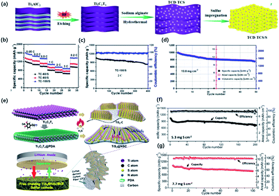 | ||
| Fig. 12 (a) Schematic of the preparation of the hybrid of Ti3C2 quantum dots and Ti3C2 sheets (TCD–TCS) and TCD–TCS/S. (b) Rate performance of the TCD–TCS/S tailoring at different temperatures: TC-60/S, TC-80/S, and TC-100/S electrodes with ASL of 1.8 mg cm−2. (c, d) Cycling performance of (c) TC-100/S at 2C with ASL of 1.8 mg cm−2, (d) 0.05C with high ASL of 13.8 mg cm−2.41 This figure has been reproduced from ref. 41 with permission from American Chemical Society, copyright 2019. (e) Schematic illustration of the synthesis of sandwich-like, single-layer TiS2 nanosheets confined within PDA-derived N, S co-doped porous carbon (TiS2@NSC). (f, g) Cycling performance of the freestanding S/TiS2@NSC@CFs electrode with different areal sulfur loading at 0.1C.98 This figure has been reproduced from ref. 98 with permission from Wiley-VCH, copyright 2019. | ||
Different dimensions of MXene derivatives show great potential as the electrode in Li–S battery, providing more adsorption sites to capture LiPSs. The porous structure also guarantees the efficient diffusion of LiPSs in the electrode, even at high sulfur loading. In the future, considerate attention can be devoted to the combination of nanomaterials for the design of electrodes and modification of separators.
5 Conclusions
2D transition metal carbide/nitrides, especially the Ti3C2Tx derivatives, have been considered promising materials for ECS. Herein, we summarize the typical synthetic routes of MXene and four different forms of derivatives, 0D quantum dots, 1D nanoribbons, 2D nanosheets and 3D nanoflowers. Furthermore, recent works involving their applications in ECS are presented. The advantages and expected applications of MXene derivatives are summarized in Table 3.| Structure of MXene derivatives | Advantages | Expected applications |
|---|---|---|
| 0D MQDs | Extraordinarily small size, good solubility | Photocatalysis |
| 1D MNRs | Shorter transport length, more exposed active sites | Electrocatalysis, metal ion batteries |
| 2D MNSs | Perfect base material with large planes, good electron conductivity | Photocatalysis, rechargeable batteries |
| 3D MNFs | Porous structure with large surface area, structural stability | Photocatalysis, rechargeable batteries |
It should be pointed out that synthetic methods determine the morphology and chemical properties of the derivatives. In particular, 0D MQDs exhibit extraordinarily small size and luminescence properties because of the quantum confinement and edge effects. The unique characteristics of MQDs have shown great potential in many fields, including sensing, biomedical, catalysis and energy storage. 1D nanoribbons and 3D nanoflowers, which are obtained via shaking and hydrothermal treatment under alkali conditions, respectively, form a porous network structure. The as-obtained titanates with 3D porous structures have shown infinite potential in energy storage and conversion applications. Moreover, the partial or complete oxidation of MXene sheets produces TiO2 with a well-preserved layered structure. The in situ formed interface optimizes the charge transfer, realizing the further application of TiO2 in photocatalysis.
By taking advantage of structural superiority and intrinsic properties, MXene derivatives showed improved performance in ECS. Although enormous progress has been achieved on the structural design and applications of MXene derivatives, there are still some remaining challenges. For example, proper attention should be devoted to deeply understand the forming mechanism of nanostructure to better control the beneficial morphology of MXene derivatives. Figuring out simple and efficient synthesis routes that make the size and morphology of resulting products (0D, 1D, 2D, 3D) controllable to improve their performance in ECS applications. Developing new material systems for enhanced performance based on the matching of physical mechanics and corresponding applications. Research related to the nanostructure derived from MXene is still in an early stage of development, so more effort should be paid into the design of MXene derivatives in the future.
Conflicts of interest
There are no conflicts to declare.Acknowledgements
This study is supported by the National Natural Science Funds (21878226).References
- M. Chhowalla, H. S. Shin, G. Eda, L.-J. Li, K. P. Loh and H. Zhang, Nat. Chem., 2013, 5, 263–275 CrossRef PubMed.
- Q. Yun, L. Li, Z. Hu, Q. Lu, B. Chen and H. Zhang, Adv. Mater., 2020, 32(1), 1903826 CrossRef CAS PubMed.
- K. K. Kim, A. Hsu, X. Jia, S. M. Kim, Y. Shi, M. Dresselhaus, T. Palacios and J. Kong, ACS Nano, 2012, 6, 8583–8590 CrossRef CAS PubMed.
- Y. Kubota, K. Watanabe, O. Tsuda and T. Taniguchi, Science, 2007, 317, 932–934 CrossRef CAS PubMed.
- M. Batmunkh, A. Shrestha, M. Bat-Erdene, M. J. Nine, C. J. Shearer, C. T. Gibson, A. D. Slattery, S. A. Tawfik, M. J. Ford, S. Dai, S. Qiao and J. G. Shapter, Angew. Chem., Int. Ed., 2018, 57, 2644–2647 CrossRef CAS PubMed.
- H. Liu, Y. Du, Y. Deng and P. D. Ye, Chem. Soc. Rev., 2015, 44, 2732–2743 RSC.
- C. Grazianetti, E. Cinquanta and A. Molle, 2D Mater., 2016, 3(1), 012001 CrossRef.
- J. Zhao, H. Liu, Z. Yu, R. Quhe, S. Zhou, Y. Wang, C. C. Liu, H. Zhong, N. Han, J. Lu, Y. Yao and K. Wu, Prog. Mater. Sci., 2016, 83, 24–151 CrossRef CAS.
- M. Naguib, M. Kurtoglu, V. Presser, J. Lu, J. Niu, M. Heon, L. Hultman, Y. Gogotsi and M. W. Barsoum, Adv. Mater., 2011, 23, 4248–4253 CrossRef CAS PubMed.
- M. R. Lukatskaya, S. Kota, Z. Lin, M.-Q. Zhao, N. Shpigel, M. D. Levi, J. Halim, P.-L. Taberna, M. Barsoum, P. Simon and Y. Gogotsi, Nat. Energy, 2017, 2(8), 17105 CrossRef CAS.
- M. Boota, B. Anasori, C. Voigt, M.-Q. Zhao, M. W. Barsoum and Y. Gogotsi, Adv. Mater., 2016, 28, 1517–1522 CrossRef CAS PubMed.
- M. Naguib, V. N. Mochalin, M. W. Barsoum and Y. Gogotsi, Adv. Mater., 2014, 26, 992–1005 CrossRef CAS PubMed.
- J. Li, X. Yuan, C. Lin, Y. Yang, L. Xu, X. Du, J. Xie, J. Lin and J. Sun, Adv. Energy Mater., 2017, 7(15), 1602725 CrossRef.
- M.-Q. Zhao, M. Torelli, C. E. Ren, M. Ghidiu, Z. Ling, B. Anasori, M. W. Barsoum and Y. Gogotsi, Nano Energy, 2016, 30, 603–613 CrossRef CAS.
- K. S. Novoselov, D. Jiang, F. Schedin, T. J. Booth, V. V. Khotkevich, S. V. Morozov and A. K. Geim, Proc. Natl. Acad. Sci. U. S. A., 2005, 102, 10451–10453 CrossRef CAS PubMed.
- R. B. Rakhi, B. Ahmed, M. N. Hedhili, D. H. Anjum and H. N. Alshareef, Chem. Mater., 2015, 27, 5314–5323 CrossRef CAS.
- M. Naguib, J. Halim, J. Lu, K. M. Cook, L. Hultman, Y. Gogotsi and M. W. Barsoum, J. Am. Chem. Soc., 2013, 135, 15966–15969 CrossRef CAS PubMed.
- J. M. Liang, C. Y. Ding, J. P. Liu, T. Chen, W. C. Peng, Y. Li, F. B. Zhang and X. B. Fan, Nanoscale, 2019, 11, 10992–11000 RSC.
- Z. M. Sun, S. Li, R. Ahuja and J. M. Schneider, Solid State Commun., 2004, 129, 589–592 CrossRef CAS.
- X. Sang, Y. Xie, M.-W. Lin, M. Alhabeb, K. L. Van Aken, Y. Gogotsi, P. R. C. Kent, K. Xiao and R. R. Unocic, ACS Nano, 2016, 10, 9193–9200 CrossRef CAS PubMed.
- M.-S. Cao, Y.-Z. Cai, P. He, J.-C. Shu, W.-Q. Cao and J. Yuan, Chem. Eng. J., 2019, 359, 1265–1302 CrossRef CAS.
- M. Naguib, O. Mashtalir, J. Carle, V. Presser, J. Lu, L. Hultman, Y. Gogotsi and M. W. Barsoum, ACS Nano, 2012, 6, 1322–1331 CrossRef CAS PubMed.
- M. Ghidiu, M. R. Lukatskaya, M.-Q. Zhao, Y. Gogotsi and M. W. Barsoum, Nature, 2014, 516, U78–U171 CrossRef PubMed.
- A. Lipatov, M. Alhabeb, M. R. Lukatskaya, A. Boson, Y. Gogotsi and A. Sinitskii, Adv. Electron. Mater., 2016, 2(12), 1600255 CrossRef.
- J. Zhao, L. Zhang, X.-Y. Xie, X. Li, Y. Ma, Q. Liu, W.-H. Fang, X. Shi, G. Cui and X. Sun, J. Mater. Chem. A, 2018, 6, 24031–24035 RSC.
- O. Mashtalir, M. Naguib, V. N. Mochalin, Y. Dall’Agnese, M. Heon, M. W. Barsoum and Y. Gogotsi, Nat. Commun., 2013, 4, 1716 CrossRef PubMed.
- M. Naguib, R. R. Unocic, B. L. Armstrong and J. Nanda, Dalton Trans., 2015, 44, 9353–9358 RSC.
- I. R. Shein and A. L. Ivanovskii, Comput. Mater. Sci., 2012, 65, 104–114 CrossRef CAS.
- P. Urbankowski, B. Anasori, T. Makaryan, D. Er, S. Kota, P. L. Walsh, M. Zhao, V. B. Shenoy, M. W. Barsoum and Y. Gogotsi, Nanoscale, 2016, 8, 11385–11391 RSC.
- T. Li, L. Yao, Q. Liu, J. Gu, R. Luo, J. Li, X. Yan, W. Wang, P. Liu, B. Chen, W. Zhang, W. Abbas, R. Naz and D. Zhang, Angew. Chem., Int. Ed., 2018, 57, 6115–6119 CrossRef CAS PubMed.
- T. Li, X. Yan, L. Huang, J. Li, L. Yao, Q. Zhu, W. Wang, W. Abbas, R. Naz, J. Gu, Q. Liu, W. Zhang and D. Zhang, J. Mater. Chem. A, 2019, 7, 14462–14465 RSC.
- S. Yang, P. Zhang, F. Wang, A. G. Ricciardulli, M. R. Lohe, P. W. M. Blom and X. Feng, Angew. Chem., Int. Ed., 2018, 57, 15491–15495 CrossRef CAS PubMed.
- M. R. Lukatskaya, J. Halim, B. Dyatkin, M. Naguib, Y. S. Buranova, M. W. Barsoum and Y. Gogotsi, Angew. Chem., Int. Ed., 2014, 53, 4877–4880 CrossRef CAS PubMed.
- W. Sun, S. A. Shah, Y. Chen, Z. Tan, H. Gao, T. Habib, M. Radovic and M. J. Green, J. Mater. Chem. A, 2017, 5, 21663–21668 RSC.
- Y. Gogotsi, Nat. Mater., 2015, 14, 1079–1080 CrossRef CAS PubMed.
- C. Xu, L. Wang, Z. Liu, L. Chen, J. Guo, N. Kang, X.-L. Ma, H.-M. Cheng and W. Ren, Nat. Mater., 2015, 14(11), 1135–1141 CrossRef CAS PubMed.
- J. Jia, T. Xiong, L. Zhao, F. Wang, H. Liu, R. Hu, J. Zhou, W. Zhou and S. Chen, ACS Nano, 2017, 11, 12509–12518 CrossRef CAS PubMed.
- X. Xiao, H. Yu, H. Jin, M. Wu, Y. Fang, J. Sun, Z. Hu, T. Li, J. Wu, L. Huang, Y. Gogotsi and J. Zhou, ACS Nano, 2017, 11, 2180–2186 CrossRef CAS PubMed.
- Z. Zhang, F. Zhang, H. C. Wang, C. H. Chan, W. Lu and J. Y. Dai, J. Mater. Chem. C, 2017, 5, 10822–10827 RSC.
- Q. Xue, H. Zhang, M. Zhu, Z. Pei, H. Li, Z. Wang, Y. Huang, Y. Huang, Q. Deng, J. Zhou, S. Du, Q. Huang and C. Zhi, Adv. Mater., 2017, 29(15), 1604847 CrossRef PubMed.
- Z. Xiao, Z. Li, P. Li, X. Meng and R. Wang, ACS Nano, 2019, 13, 3608–3617 CrossRef CAS PubMed.
- Y. Li, L. Ding, Y. Guo, Z. Liang, H. Cui and J. Tian, ACS Appl. Mater. Interfaces, 2019, 11, 41440–41447 CrossRef CAS PubMed.
- G. Xu, Y. Niu, X. Yang, Z. Jin, Y. Wang, Y. Xu and H. Niu, Adv. Opt. Mater., 2018, 6, 1800951 CrossRef.
- Y. Feng, F. Zhou, Q. Deng and C. Peng, Ceram. Int., 2020, 46, 8320–8327 CrossRef CAS.
- Q. Zhang, Y. Sun, M. Liu and Y. Liu, Nanoscale, 2020, 12, 1826–1832 RSC.
- Y. Qin, Z. Wang, N. Liu, Y. Sun, D. Han, Y. Liu, L. Niu and Z. Kang, Nanoscale, 2018, 10, 14000–14004 RSC.
- P. C. Lian, Y. F. Dong, Z. S. Wu, S. H. Zheng, X. H. Wang, S. Wang, C. L. Sun, J. Q. Qin, X. Y. Shi and X. H. Bao, Nano Energy, 2017, 40, 1–8 CrossRef CAS.
- Y. Dong, S. Zheng, J. Qin, X. Zhao, H. Shi, X. Wang, J. Chen and Z. S. Wu, ACS Nano, 2018, 12, 2381–2388 CrossRef CAS PubMed.
- J. Huang, R. Meng, L. Zu, Z. Wang, N. Feng, Z. Yang, Y. Yu and J. Yang, Nano Energy, 2018, 46, 20–28 CrossRef CAS.
- N. Li, Y. Jiang, C. Zhou, Y. Xiao, B. Meng, Z. Wang, D. Huang, C. Xing and Z. Peng, ACS Appl. Mater. Interfaces, 2019, 11, 38116–38125 CrossRef CAS PubMed.
- W. Yuan, L. Cheng, Y. An, H. Wu, N. Yao, X. Fan and X. Guo, ACS Sustainable Chem. Eng., 2018, 6, 8976–8982 CrossRef CAS.
- H. Wang, H. Cui, X. Song, R. Xu, N. Wei, J. Tian and H. Niu, J. Colloid Interface Sci., 2020, 561, 46–57 CrossRef CAS PubMed.
- J. Wang, Y. Shen, S. Liu and Y. Zhang, Appl. Catal., B, 2020, 270, 118885 CrossRef CAS.
- X. Zhang, Y. Liu, S. Dong, Z. Ye and Y. Guo, Ceram. Int., 2017, 43, 11065–11070 CrossRef CAS.
- H. Huang, Y. Song, N. Li, D. Chen, Q. Xu, H. Li, J. He and J. Lu, Appl. Catal., B, 2019, 251, 154–161 CrossRef CAS.
- W. Yuan, L. Cheng, H. Wu, Y. Zhang, S. Lv and X. Guo, Chem. Commun., 2018, 54, 2755–2758 RSC.
- Y. Dong, Z. S. Wu, S. Zheng, X. Wang, J. Qin, S. Wang, X. Shi and X. Bao, ACS Nano, 2017, 11, 4792–4800 CrossRef CAS PubMed.
- Y. Li, X. Deng, J. Tian, Z. Liang and H. Cui, Appl. Mater. Today, 2018, 13, 217–227 CrossRef.
- G. Zou, B. Liu, J. Guo, Q. Zhang, C. Fernandez and Q. Peng, ACS Appl. Mater. Interfaces, 2017, 9, 7611–7618 CrossRef CAS PubMed.
- D. Pan, J. Zhang, Z. Li and M. Wu, Adv. Mater., 2010, 22, 734–738 CrossRef CAS PubMed.
- S. Xu, D. Li and P. Wu, Adv. Funct. Mater., 2015, 25, 1127–1136 CrossRef CAS.
- B. Shao, Z. Liu, G. Zeng, H. Wang, Q. Liang, Q. He, M. Cheng, C. Zhou, L. Jiang and B. Song, J. Mater. Chem. A, 2020, 8, 7508–7535 RSC.
- X. Chen, X. Sun, W. Xu, G. Pan, D. Zhou, J. Zhu, H. Wang, X. Bai, B. Dong and H. Song, Nanoscale, 2018, 10, 1111–1118 RSC.
- Z. Guo, X. Zhu, S. Wang, C. Lei, Y. Huang, Z. Nie and S. Yao, Nanoscale, 2018, 10, 19579–19585 RSC.
- Z. Wang, J. Xuan, Z. Zhao, Q. Li and F. Geng, ACS Nano, 2017, 11, 11559–11565 CrossRef CAS PubMed.
- X. Yu, X. Cai, H. Cui, S.-W. Lee, X.-F. Yu and B. Liu, Nanoscale, 2017, 9, 17859–17864 RSC.
- Q. Lu, J. Wang, B. Li, C. Weng, X. Li, W. Yang, X. Yan, J. Hong, W. Zhu and X. Zhou, Anal. Chem., 2020, 92, 7770–7777 CrossRef CAS PubMed.
- K. Wang, R. Jiang, T. Peng, X. Chen, W. Dai and X. Fu, Appl. Catal., B, 2019, 256, 117780 CrossRef.
- Q. Xu, L. Ding, Y. Wen, W. Yang, H. Zhou, X. Chen, J. Street, A. Zhou, W.-J. Ong and N. Li, J. Mater. Chem. C, 2018, 6, 6360–6369 RSC.
- M. Malaki, A. Maleki and R. S. Varma, J. Mater. Chem. A, 2019, 7, 10843–10857 RSC.
- H. Xu, B. W. Zeiger and K. S. Suslick, Chem. Soc. Rev., 2013, 42, 2555–2567 RSC.
- R. H. Baughman, A. A. Zakhidov and W. A. de Heer, Science, 2002, 297, 787–792 CrossRef CAS PubMed.
- A. S. Arico, P. Bruce, B. Scrosati, J. M. Tarascon and W. Van Schalkwijk, Nat. Mater., 2005, 4, 366–377 CrossRef CAS PubMed.
- W. Zeng, L. Shu, Q. Li, S. Chen, F. Wang and X.-M. Tao, Adv. Mater., 2014, 26, 5310–5336 CrossRef CAS PubMed.
- T. Yamada, Y. Hayamizu, Y. Yamamoto, Y. Yomogida, A. Izadi-Najafabadi, D. N. Futaba and K. Hata, Nat. Nanotechnol., 2011, 6, 296–301 CrossRef CAS PubMed.
- X. L. Li, X. R. Wang, L. Zhang, S. W. Lee and H. J. Dai, Science, 2008, 319, 1229–1232 CrossRef CAS PubMed.
- P. Lian, Y. Dong, Z.-S. Wu, S. Zheng, X. Wang, W. Sen, C. Sun, J. Qin, X. Shi and X. Bao, Nano Energy, 2017, 40, 1–8 CrossRef CAS.
- B. Zhang, J. Zhu, P. Shi, W. Wu and F. Wang, Ceram. Int., 2019, 45, 8395–8405 CrossRef CAS.
- X. Wu, Z. Wang, M. Yu, L. Xiu and J. Qiu, Adv. Mater., 2017, 29(24), 1607017 CrossRef PubMed.
- C. F. J. Zhang, S. Pinilla, N. McEyoy, C. P. Cullen, B. Anasori, E. Long, S. H. Park, A. Seral-Ascaso, A. Shmeliov, D. Krishnan, C. Morant, X. H. Liu, G. S. Duesberg, Y. Gogotsi and V. Nicolosi, Chem. Mater., 2017, 29, 4848–4856 CrossRef CAS.
- B. Lyu, Y. Choi, H. Jing, C. Qian, H. Kang, S. Lee and J. H. Cho, Adv. Mater., 2020, 32, e1907633 CrossRef PubMed.
- W. Yuan, L. Cheng, Y. Zhang, H. Wu, S. Lv, L. Chai, X. Guo and L. Zheng, Adv. Mater. Interfaces, 2017, 4, 1700577 CrossRef.
- T. D. Nguyen, E. Lizundia, M. Niederberger, W. Y. Hamad and M. J. MacLachlan, Chem. Mater., 2019, 31, 2174–2181 CrossRef CAS.
- Y. Li, L. Ding, Z. Liang, Y. Xue, H. Cui and J. Tian, Chem. Eng. J., 2020, 383, 123178 CrossRef CAS.
- C. Yang, Y. Liu, X. Sun, Y. R. Zhang, L. R. Hou, Q. A. Zhang and C. Z. Yuan, Electrochim. Acta, 2018, 271, 165–172 CrossRef CAS.
- S. Y. Chae, M. K. Park, S. K. Lee, T. Y. Kim, S. K. Kim and W. I. Lee, Chem. Mater., 2003, 15, 3326–3331 CrossRef CAS.
- L. Jia, Y. Li, L. Su, D. Liu, Y. Fu, J. Li, X. Yan and D. He, ChemistrySelect, 2020, 5, 3124–3129 CrossRef CAS.
- L. Li, G. Jiang, C. An, Z. Xie, Y. Wang, L. Jiao and H. Yuan, Nanoscale, 2020, 12, 10369–10379 RSC.
- H. G. Yang, C. H. Sun, S. Z. Qiao, J. Zou, G. Liu, S. C. Smith, H. M. Cheng and G. Q. Lu, Nature, 2008, 453, 638–641 CrossRef CAS PubMed.
- C. Peng, X. Yang, Y. Li, H. Yu, H. Wang and F. Peng, ACS Appl. Mater. Interfaces, 2016, 8, 6051–6060 CrossRef CAS PubMed.
- Y. Li, Z. Yin, G. Ji, Z. Liang, Y. Xue, Y. Guo, J. Tian, X. Wang and H. Cui, Appl. Catal., B, 2019, 246, 12–20 CrossRef CAS.
- C. Peng, P. Wei, X. Li, Y. Liu, Y. Cao, H. Wang, H. Yu, F. Peng, L. Zhang, B. Zhang and K. Lv, Nano Energy, 2018, 53, 97–107 CrossRef CAS.
- Y. J. Xu, S. Wang, J. Yang, B. Han, R. Nie, J. X. Wang, J. G. Wang and H. W. Jing, Nano Energy, 2018, 51, 442–450 CrossRef CAS.
- J. Low, L. Zhang, T. Tong, B. Shen and J. Yu, J. Catal., 2018, 361, 255–266 CrossRef CAS.
- T. Hou, Q. Li, Y. Zhang, W. Zhu, K. Yu, S. Wang, Q. Xu, S. Liang and L. Wang, Appl. Catal., B, 2020, 273, 119072 CrossRef CAS.
- M. Naguib, O. Mashtalir, M. R. Lukatskaya, B. Dyatkin, C. F. Zhang, V. Presser, Y. Gogotsi and M. W. Barsoum, Chem. Commun., 2014, 50, 7420–7423 RSC.
- H. Ghassemi, W. Harlow, O. Mashtalir, M. Beidaghi, M. R. Lukatskaya, Y. Gogotsi and M. L. Taheri, J. Mater. Chem. A, 2014, 2, 14339–14343 RSC.
- X. Huang, J. Tang, B. Luo, R. Knibbe, T. Lin, H. Hu, M. Rana, Y. Hu, X. Zhu, Q. Gu, D. Wang and L. Wang, Adv. Energy Mater., 2019, 9, 1901872 CrossRef.
- X. Zhang, J. Li, J. Li, L. Han, T. Lu, X. Zhang, G. Zhu and L. Pan, Chem. Eng. J., 2020, 385, 123394 CrossRef CAS.
- Q. Xu, J. Xu, H. Jia, Q. Tian, P. Liu, S. Chen, Y. Cai, X. Lu, X. Duan and L. Lu, J. Electroanal. Chem., 2020, 860, 113869 CrossRef CAS.
- W. Q. Fang, X.-Q. Gong and H. G. Yang, J. Phys. Chem. Lett., 2011, 2, 725–734 CrossRef CAS.
- G. Zou, J. Guo, Q. Peng, A. Zhou, Q. Zhang and B. Liu, J. Mater. Chem. A, 2016, 4, 489–499 RSC.
- R. Asahi, T. Morikawa, T. Ohwaki, K. Aoki and Y. Taga, Science, 2001, 293, 269–271 CrossRef CAS PubMed.
- G. Zhang, M. Zhang, X. Ye, X. Qiu, S. Lin and X. Wang, Adv. Mater., 2014, 26, 805–809 CrossRef CAS PubMed.
- B. Wu, D. Liu, S. Mubeen, T. T. Chuong, M. Moskovits and G. D. Stucky, J. Am. Chem. Soc., 2016, 138, 1114–1117 CrossRef CAS PubMed.
- Y. Huo, J. Zhang, K. Dai, Q. Li, J. Lv, G. Zhu and C. Liang, Appl. Catal., B, 2019, 241, 528–538 CrossRef CAS.
- J. Ran, G. Gao, F.-T. Li, T.-Y. Ma, A. Du and S.-Z. Qiao, Nat. Commun., 2017, 8, 13907 CrossRef CAS PubMed.
- X. Han, L. An, Y. Hu, Y. Li, C. Hou, H. Wang and Q. Zhang, Appl. Catal., B, 2020, 265, 118539 CrossRef CAS.
- G. Lui, J.-Y. Liao, A. Duan, Z. Zhang, M. Fowler and A. Yu, J. Mater. Chem. A, 2013, 1, 12255–12262 RSC.
- G. Wu, J. Wang, D. F. Thomas and A. Chen, Langmuir, 2008, 24, 3503–3509 CrossRef CAS PubMed.
- G. Gao, A. P. O'Mullane and A. Du, ACS Catal., 2017, 7, 494–500 CrossRef CAS.
- J. Deng, P. Ren, D. Deng, L. Yu, F. Yang and X. Bao, Energy Environ. Sci., 2014, 7, 1919–1923 RSC.
- L. Li, P. Wang, Q. Shao and X. Huang, Chem. Soc. Rev., 2020, 49, 3072–3106 RSC.
- S. Jiao, Z. Yao, F. Xue, Y. Lu, M. Liu, H. Deng, X. Ma, Z. Liu, C. Ma, H. Huang, S. Ruan and Y.-J. Zeng, Appl. Catal., B, 2019, 258, 117964 CrossRef CAS.
- C. He, T. Bo, B. Wang and J. Tao, Nano Energy, 2019, 62, 85–93 CrossRef CAS.
- X. Yang, N. Gao, S. Zhou and J. Zhao, Phys. Chem. Chem. Phys., 2018, 20, 19390–19397 RSC.
- C. Yang, Y. Liu, X. Sun, Y. Zhang, L. Hou, Q. Zhang and C. Yuan, Electrochim. Acta, 2018, 271, 165–172 CrossRef CAS.
- P. Wang, X. Lu, Y. Boyjoo, X. Wei, Y. Zhang, D. Guo, S. Sun and J. Liu, J. Power Sources, 2020, 451, 227756 CrossRef CAS.
- Y. Jiang, Y. Deng, B. Zhang, W. Hua, X. Wang, Q. Qi, Q. Lin and W. Lv, Nanoscale, 2020, 12(23), 12308–12316 RSC.
- L. Jiao, C. Zhang, C. N. Geng, S. C. Wu, H. Li, W. Lv, Y. Tao, Z. J. Chen, G. M. Zhou, J. Li, G. W. Ling, Y. Wan and Q. H. Yang, Adv. Energy Mater., 2019, 9, 9 Search PubMed.
- Y. Xie, M. Naguib, V. N. Mochalin, M. W. Barsoum, Y. Gogotsi, X. Yu, K.-W. Nam, X.-Q. Yang, A. I. Kolesnikov and P. R. C. Kent, J. Am. Chem. Soc., 2014, 136, 6385–6394 CrossRef CAS PubMed.
- Q. Wei, F. Xiong, S. Tan, L. Huang, E. H. Lan, B. Dunn and L. Mai, Adv. Mater., 2017, 29(20), 1602300 CrossRef PubMed.
- L. Wang, G. Yang, S. Peng, J. Wang, W. Yan and S. Ramakrishna, Energy Storage Materials, 2020, 25, 443–476 CrossRef.
- S. Kajiyama, L. Szabova, K. Sodeyama, H. Iinuma, R. Morita, K. Gotoh, Y. Tateyama, M. Okubo and A. Yamada, ACS Nano, 2016, 10, 3334–3341 CrossRef CAS.
- A. Manthiram, Y. Fu, S.-H. Chung, C. Zu and Y.-S. Su, Chem. Rev., 2014, 114, 11751–11787 CrossRef CAS PubMed.
- D.-W. Wang, Q. Zeng, G. Zhou, L. Yin, F. Li, H.-M. Cheng, I. R. Gentle and G. Q. M. Lu, J. Mater. Chem. A, 2013, 1, 9382–9394 RSC.
- X. Zhao, M. Liu, Y. Chen, B. Hou, N. Zhang, B. Chen, N. Yang, K. Chen, J. Li and L. An, J. Mater. Chem. A, 2015, 3, 7870–7876 RSC.
- X. Tang, X. Guo, W. Wu and G. Wang, Adv. Energy Mater., 2018, 8(33), 1801897 CrossRef.
- X. Liang, A. Garsuch and L. F. Nazar, Angew. Chem., Int. Ed., 2015, 54, 3907–3911 CrossRef CAS PubMed.
- Z.-L. Xu, S. Lin, N. Onofrio, L. Zhou, F. Shi, W. Lu, K. Kang, Q. Zhang and S. P. Lau, Nat. Commun., 2018, 9, 4164 CrossRef PubMed.
- Y. Hu, W. Chen, T. Lei, B. Zhou, Y. Jiao, Y. Yan, X. Du, J. Huang, C. Wu, X. Wang, Y. Wang, B. Chen, J. Xu, C. Wang and J. Xiong, Adv. Energy Mater., 2019, 9(7), 1802955 CrossRef.
- G. Wang, J. Mol. Catal. A: Chem., 2007, 274, 185–191 CrossRef CAS.
- N. M. Tran, Q. T. H. Ta and J.-S. Noh, Appl. Surf. Sci., 2021, 538, 148023 CrossRef.
- X. Gao, B. Wang, K. Wang, S. Xu, S. Liu, X. Liu, Z. Jia and G. Wu, J. Colloid Interface Sci., 2021, 583, 510–521 CrossRef CAS PubMed.
- W. Zhong, M. Tao, W. Tang, W. Gao, T. Yang, Y. Zhang, R. Zhan, S.-J. Bao and M. Xu, Chem. Eng. J., 2019, 378, 122209 CrossRef CAS.
- P. Li, W. Wang, S. Gong, F. Lv, H. Huang, M. Luo, Y. Yang, C. Yang, J. Zhou, C. Qian, B. Wang, Q. Wang and S. Guo, ACS Appl. Mater. Interfaces, 2018, 10, 37974–37980 CrossRef CAS PubMed.
- X. He, S. Jin, L. Miao, Y. Cai, Y. Hou, H. Li, K. Zhang, Z. Yan and J. Chen, Angew. Chem., Int. Ed., 2020, 59, 16705–16711 CrossRef CAS.
- X. Lu, J. Zhu, W. Wu and B. Zhang, Electrochim. Acta, 2017, 228, 282–289 CrossRef CAS.
| This journal is © The Royal Society of Chemistry 2021 |


